1993 DODGE TRUCK radiator
[x] Cancel search: radiatorPage 749 of 1502
9 - 146 5.9L (DIESEL) ENGINE
•
DIAL
INDICATOR
CYLINDER BLOCK
GASKET
J9109-97
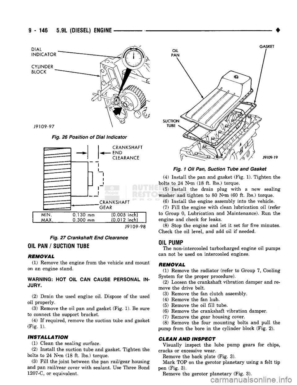
Fig.
26 Position of Dial Indicator CRANKSHAFT
END
CLEARANCE
CRANKSHAFT
GEAR
MIN.
MAX.
0.130
mm
0.300 mm (0M5 inch)
(0.012 inch)
J9109-98
Fig.
27 Crankshaft End Clearance
OIL PAN / SUCTION TU1E
REMOVAL (1) Remove the engine from the vehicle and mount
on an engine stand.
WARNING:
HOT OIL CAN
CAUSE PERSONAL
IN
JURY.
(2) Drain the used engine oil. Dispose of the used
oil properly. (3) Remove the oil pan and gasket (Fig. 1). Be sure
to connect the support bracket.
(4) If required, remove the suction tube and gasket
(Fig. 1).
INSTALLATION (1) Clean the sealing surface.
(2) Install the suction tube and gasket. Tighten the
bolts to 24 Nin (18 ft. lbs.) torque.
(3) Fill the joint between the pan rail/gear housing
and pan rail/rear cover with sealant. Use Three Bond 1207-C, or equivalent.
SUCTION
TUBE
J9109-19
Fig.
1 Oil Pan,
Suction
Tube and
Gasket
(4) Install the pan and gasket (Fig. 1). Tighten the
bolts to 24 N-m (18 ft. lbs.) torque.
(5) Install the drain plug with
a
new sealing
washer and tighten to 80 Nnn (60 ft. lbs.) torque.
(6) Install the engine assembly into the vehicle.
(7) Fill the engine with clean lubrication oil (refer
to Group 0, Lubrication and Maintenance). Run the engine and check for leaks.
(8) Stop the engine and let it set for five minutes.
Check the oil level, and add oil if needed.
OIL
PUMP
The non-intercooled turbocharged engine oil pumps
can not be used on intercooled engines.
REMOVAL (1) Remove the radiator (refer to Group 7, Cooling
System for the proper procedure). (2) Loosen the crankshaft vibration damper and re
move the drive belt.
(3) Remove the fan clutch assembly. (4) Remove the fan hub.
(5) Remove the oil fill tube.
(6) Remove the crankshaft vibration damper.
(7) Remove the gear housing cover.
(8) Remove the four mounting bolts and pull the
pump from the bore in the cylinder block (Fig. 2).
CLEAN AND INSPECT Visually inspect the lube pump gears for chips,
cracks or excessive wear.
Remove the back plate (Fig. 3).
Mark TOP on the gerotor planetary using a felt tip
pen (Fig. 3). Remove the gerotor planetary (Fig. 3).
Page 757 of 1502
9
- 154 5.9L
(DIESEL)
ENGINE
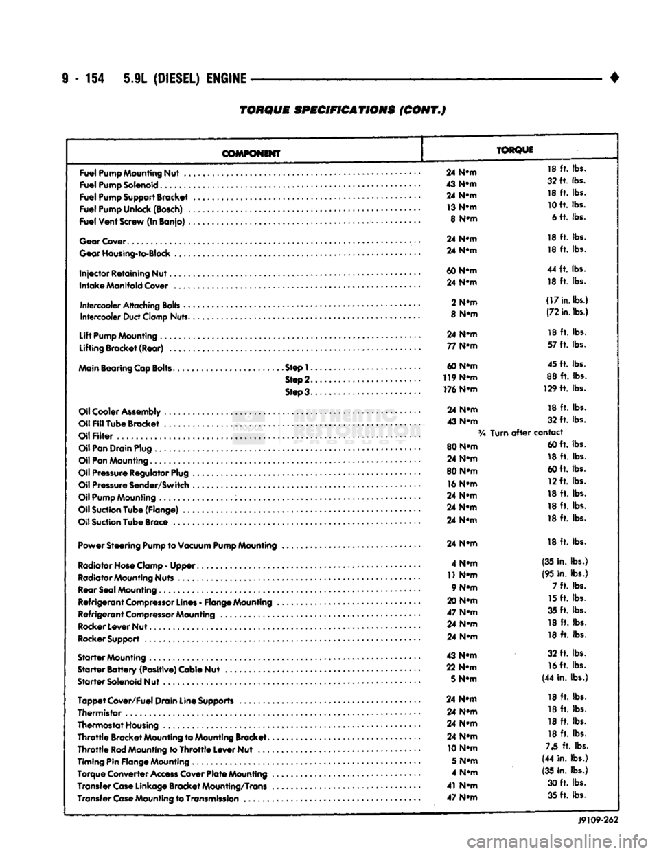
TORQUE
SPECIFICATIONS
(CONT.J
COMPONENT
TORQUE
Fuel
Pump
Mounting
Nut
..
Fuel
Pump
Solenoid
Fuel
Pump
Support
Bracket
Fuel
Pump
Unlock
(Bosch)
.
Fuel
Vent
Screw
(In Banjo)
.
Gear
Cover
Gear
Housing-to-Block
Injector
Retaining Nut.
Intake
Manifold
Cover
Intercooler
Attaching
Bolts
•
•
Intercooler
Duct
Clamp
Nuts.
Lift
Pump
Mounting
Lifting Bracket (Rear)
..
Main
Bearing
Cap
Bolts.
Step!.
Step
2.
Steo3.
Oil
Cooler
Assembly
Oil
Fill
Tube Bracket
Oil
Filter
Oil
Pan
Drain
Plug
Oil
Pan
Mounting.........
Oil
Pressure
Regulator
Plug
Oil
Pressure
Sender/Switch
Oil
Pump
Mounting
Oil
Suction
Tube (Flange)
..
Oil
Suction
Tube
Brace
Power Steering
Pump
to
Vacuum
Pump
Mounting
Radiator Hose Clamp
-
Upper
Radiator Mounting Nuts Rear Seal Mounting
Refrigerant
Compressor
Lines
-
Flange Mounting
Refrigerant
Compressor
Mounting
Rocker Lever Nut
Rocker Support
Starter
Mounting
Starter
Battery
(Positive) Cable Nut
Starter
Solenoid Nut
Tappet
Cover/Fuel Drain Line Supports
Thermistor
,
Thermostat Housing
Throttle
Bracket Mounting to Mounting Bracket.
Throttle
Rod
Mounting to
Throttle
Lever Nut
...
Timing Pin Flange Mounting
Torque Converter
Access
Cover
Plate
Mounting
Transfer
Case
Linkage Bracket Mounting/Trans Transfer
Case
Mounting to
Transmission
..
24
N-m
18
ft.
lbs.
43
N-m
32 ft. lbs.
24
N-m
18
ft.
lbs.
13
N-m
10
ft. lbs.
8
N-m
6 ft. lbs.
24
N-m
18
ft.
lbs.
24
N-m
18
ft.
lbs.
60
N-m
44
ft.
lbs.
24
N-m
18
ft.
lbs.
2
N-m
(17
in.
lbs.)
8
N-m
(72
in.
lbs.)
24
N-m
18
ft.
lbs.
77
N-m
57
ft.
lbs.
60 N-m 45 ft. lbs.
119
N-m
88
ft.
lbs.
176 N-m 129
ft.
lbs.
24
N-m
18
ft.
lbs.
43
N-m
32
ft.
lbs.
Turn
after
contact
80 N-m 60 ft. lbs.
24
N-m
18
ft.
lbs.
80 N-m 60 ft. lbs.
16
N-m
12 ft. lbs.
24
N-m
18
ft.
lbs.
24
N-m
18
ft.
lbs.
24
N-m
18
ft.
lbs.
24
N-m
18
ft.
lbs.
4
N-m
(35 in. lbs.)
11
N-m
(95 in. lbs.)
9 N-m 7
ft.
lbs.
20
N-m
15
ft.
lbs.
47
N-m
35 ft. lbs.
24
N-m
18
ft.
lbs.
24
N-m
18
ft.
lbs.
43
N-m
32
ft.
lbs.
22
N-m
16
ft. lbs.
5
N-m
(44 in. lbs.)
24
N-m
18
ft.
lbs.
24
N-m
18
ft.
lbs.
24
N-m
18
ft.
lbs.
24
N-m
18
ft.
lbs.
10 N-m
73
ft.
lbs.
5
N-m
(44 in. lbs.)
4
N-m
(35
in. lbs.)
41
N-m
30 ft. lbs.
47
N-m
35 ft. lbs.
J9109-262
Page 784 of 1502
•
EXHAUST
SYSTEM
AND
INTAKE MANIFOLD
11 - 25
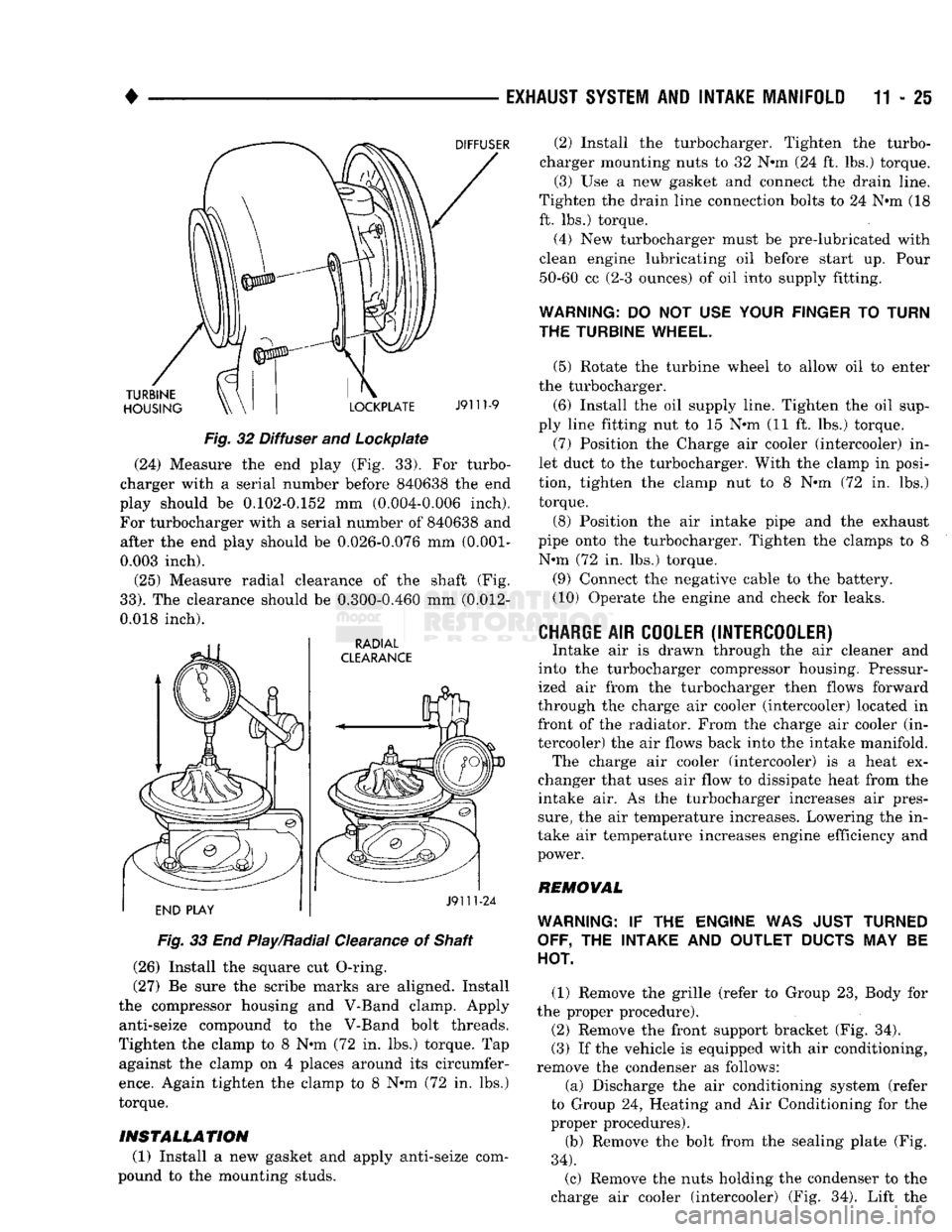
Fig.
32 Diffuser and Lockpiate (24) Measure the end play (Fig. 33). For turbo
charger with a serial number before 840638 the end
play should be 0.102-0.152 mm (0.004-0.006 inch).
For turbocharger with a serial number of 840638 and after the end play should be 0.026-0.076 mm
(0.001-
0.003 inch).
(25) Measure radial clearance of the shaft (Fig.
33).
The clearance should be 0.300-0.460 mm (0.012-
0.018 inch).
Fig.
33 End Play/Radial Clearance of Shaft
(26) Install the square cut O-ring.
(27) Be sure the scribe marks are aligned. Install
the compressor housing and V-Band clamp. Apply anti-seize compound to the V-Band bolt threads.
Tighten the clamp to 8 N-m (72 in. lbs.) torque. Tap against the clamp on 4 places around its circumfer
ence.
Again tighten the clamp to 8 N-m (72 in. lbs.)
torque.
INSTALLATION
(1) Install a new gasket and apply anti-seize com
pound to the mounting studs. (2) Install the turbocharger. Tighten the turbo
charger mounting nuts to 32 N-m (24 ft. lbs.) torque. (3) Use a new gasket and connect the drain line.
Tighten the drain line connection bolts to 24 N-m (18
ft. lbs.) torque.
(4) New turbocharger must be pre-lubricated with
clean engine lubricating oil before start up. Pour 50-60 cc (2-3 ounces) of oil into supply fitting.
WARNING:
DO NOT USE
YOUR FINGER
TO
TURN
THE TURBINE WHEEL.
(5) Rotate the turbine wheel to allow oil to enter
the turbocharger.
(6) Install the oil supply line. Tighten the oil sup
ply line fitting nut to 15 N-m (11 ft. lbs.) torque. (7) Position the Charge air cooler (intercooler) in
let duct to the turbocharger. With the clamp in posi
tion, tighten the clamp nut to 8 N-m (72 in. lbs.) torque.
(8) Position the air intake pipe and the exhaust
pipe onto the turbocharger. Tighten the clamps to 8 N-m (72 in. lbs.) torque.
(9) Connect the negative cable to the battery.
(10) Operate the engine and check for leaks.
CHARGE
AIR
COOLER (INTERCOOLER)
Intake air is drawn through the air cleaner and
into the turbocharger compressor housing. Pressur
ized air from the turbocharger then flows forward
through the charge air cooler (intercooler) located in front of the radiator. From the charge air cooler (in
tercooler) the air flows back into the intake manifold. The charge air cooler (intercooler) is a heat ex
changer that uses air flow to dissipate heat from the
intake air. As the turbocharger increases air pres
sure,
the air temperature increases. Lowering the in
take air temperature increases engine efficiency and
power.
REMOVAL
WARNING:
IF THE
ENGINE
WAS
JUST TURNED OFF,
THE
INTAKE
AND
OUTLET
DUCTS
MAY BE
HOT.
(1) Remove the grille (refer to Group 23, Body for
the proper procedure).
(2) Remove the front support bracket (Fig. 34).
(3) If the vehicle is equipped with air conditioning,
remove the condenser as follows:
(a) Discharge the air conditioning system (refer
to Group 24, Heating and Air Conditioning for the
proper procedures).
(b) Remove the bolt from the sealing plate (Fig.
34).
(c) Remove the nuts holding the condenser to the
charge air cooler (intercooler) (Fig. 34). Lift the
Page 798 of 1502
SNOW PLOW DOWN
SOLENOID
(FRONT
SNOW
PLOW
FRAME)
SNOW PLOW
RIGHT SOLENOID
(FRONT
SNOW PLOW FRAME)
TRANSMISSION
OIL
TEMPERATURE LAMP TRANSMISSION
OIL
TEMPERATURE SWITCH
(RIGHT
SIDE
BELOW RADIATOR)
8901-4
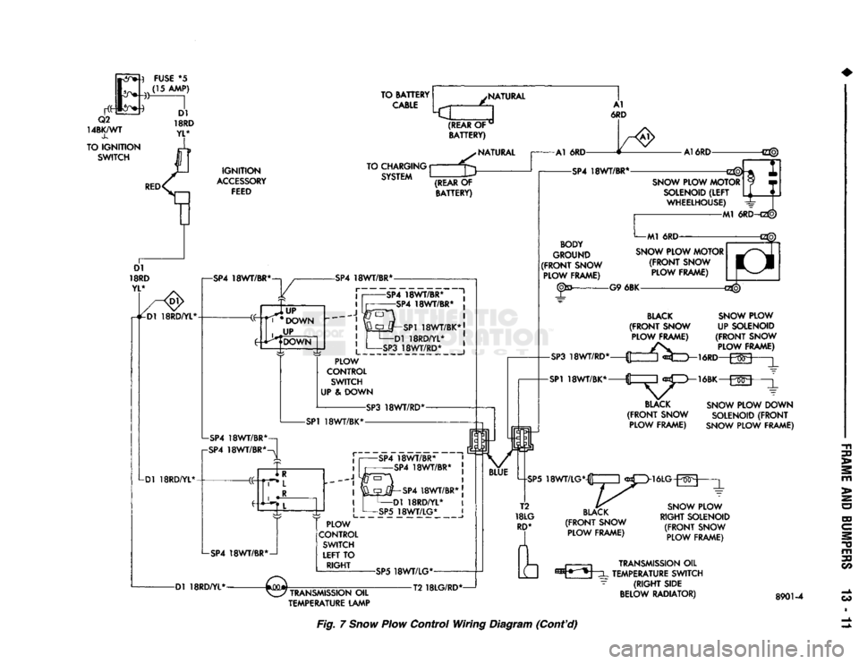
Fig.
7
Snow
Plow Control Wiring Diagram (Cont'd)
Page 799 of 1502
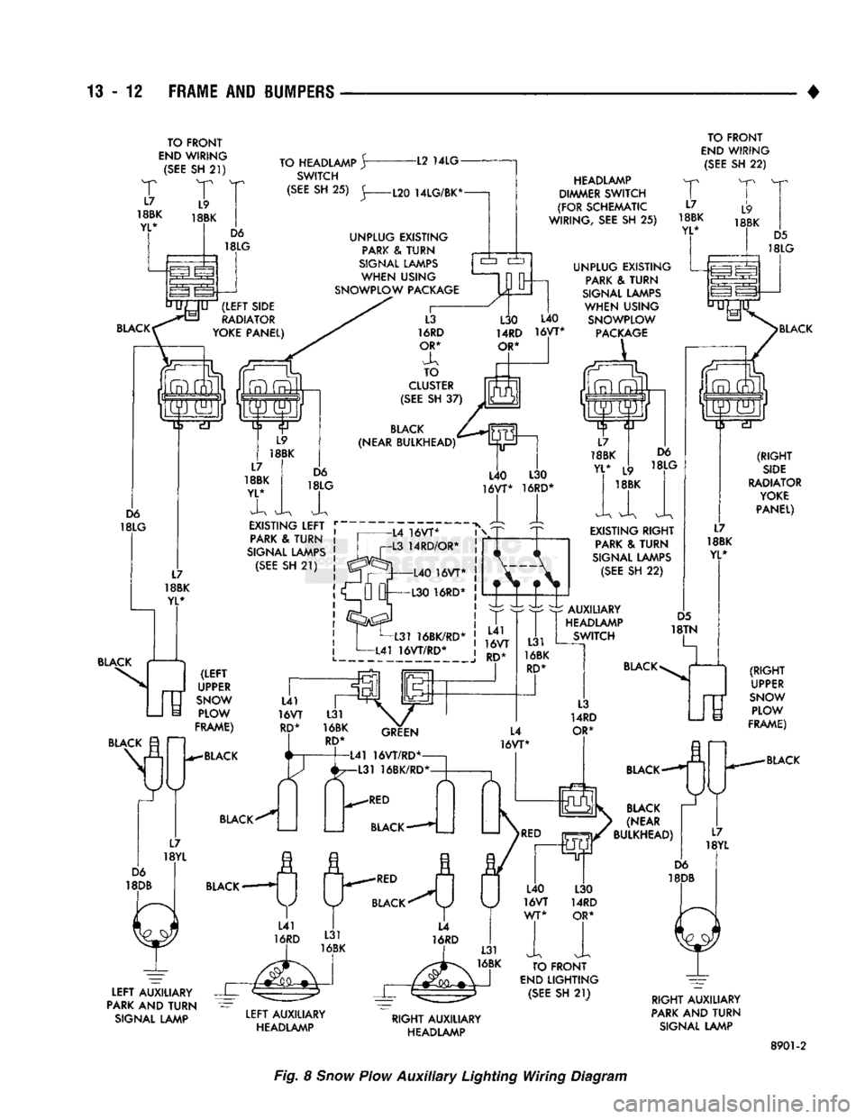
13
- 12
FRAME AND BUMPERS
TO FRONT
END
WIRING
(SEE
SH
21)
T
T
18BK
18BK
YL* TO HEADLAMP
Jr
SWITCH -L2
14LG
TO FRONT
END
WIRING
(SEE
SH
22)
BLACK (RIGHT
SIDE
RADIATOR
YOKE
PANEL) BLACK
(RIGHT
' UPPER
SNOW
PLOW
FRAME)
BLACK
LEFT
AUXILIARY
PARK AND
TURN
SIGNAL LAMP
LEFT
AUXILIARY
HEADLAMP
RIGHT
AUXILIARY
HEADLAMP
RIGHT
AUXILIARY
PARK AND
TURN
SIGNAL LAMP
8901-2
Fig. 8
Snow
Plow
Auxiliary
Lighting Wiring Diagram
Page 845 of 1502
14
- 26
FUEL
SYSTEM
•
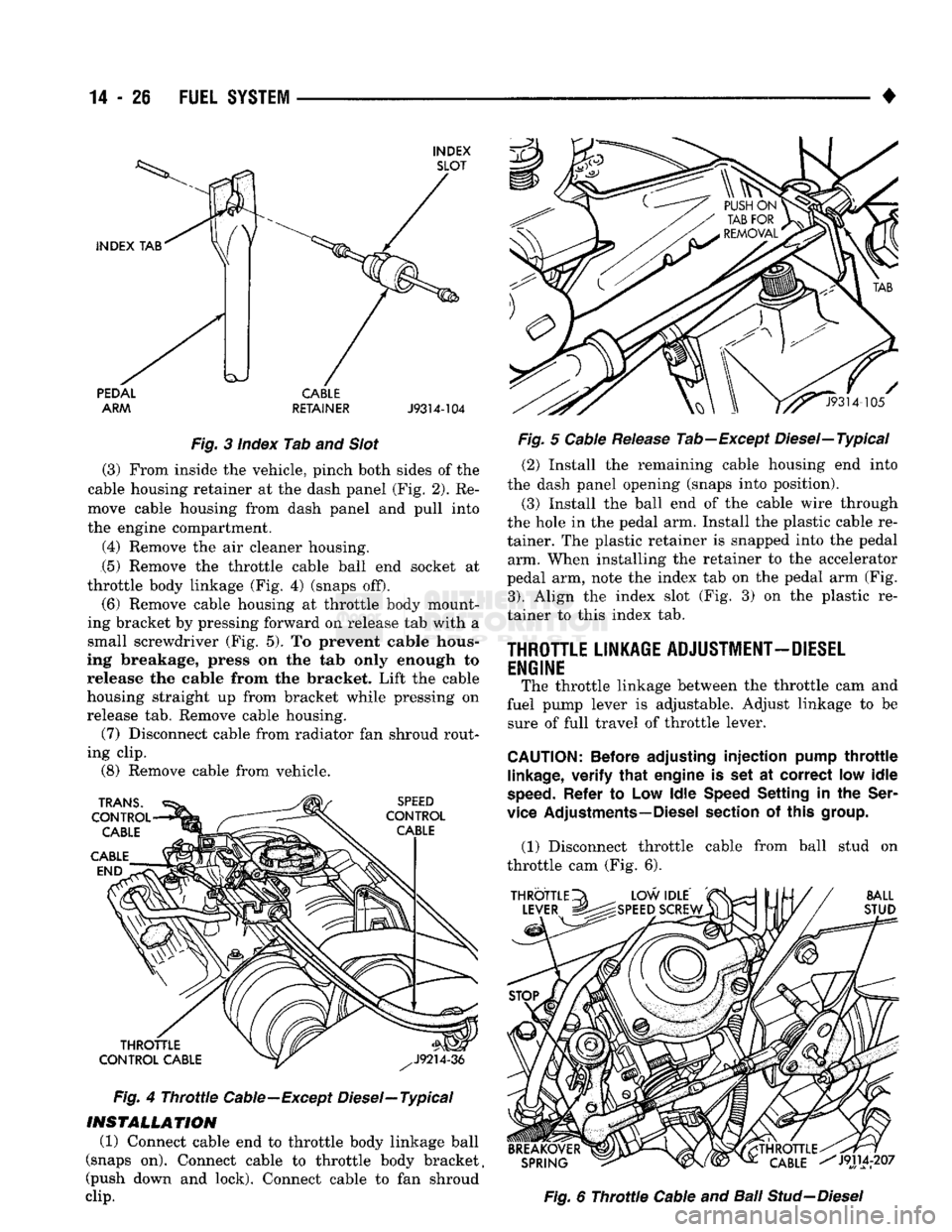
INDEX SLOT
INDEX
TAB PEDAL
ARM CABLE
RETAINER
J9314-104
Fig.
3 Index Tab and
Slot
(3) From inside the vehicle, pinch both sides of the
cable housing retainer at the dash panel (Fig. 2). Re
move cable housing from dash panel and pull into
the engine compartment.
(4) Remove the air cleaner housing. (5) Remove the throttle cable ball end socket at
throttle body linkage (Fig. 4) (snaps off).
(6) Remove cable housing at throttle body mount
ing bracket by pressing forward on release tab with a
small screwdriver (Fig. 5). To prevent cable hous
ing breakage, press on the tab only enough to release the cable from the bracket. Lift the cable
housing straight up from bracket while pressing on
release tab. Remove cable housing. (7) Disconnect cable from radiator fan shroud rout
ing clip. (8) Remove cable from vehicle.
TRANS.
CONTROL CABLE
CABLE END SPEED
CONTROL CABLE
THROTTLE
CONTROL CABLE
Fig.
4
Throttle
Cable—Except Diesel—Typical
INSTALLATION
(1) Connect cable end to throttle body linkage ball
(snaps on). Connect cable to throttle body bracket,
(push down and lock). Connect cable to fan shroud
clip.
^^J9314-105
Fig.
5 Cable
Release
Tab—Except Diesel—Typical (2) Install the remaining cable housing end into
the dash panel opening (snaps into position).
(3) Install the ball end of the cable wire through
the hole in the pedal arm. Install the plastic cable re
tainer. The plastic retainer is snapped into the pedal arm. When installing the retainer to the accelerator
pedal arm, note the index tab on the pedal arm (Fig.
3).
Align the index slot (Fig. 3) on the plastic re
tainer to this index tab.
THROTTLE LINKAGE ADJUSTMENT-DIESEL
ENGINE The throttle linkage between the throttle cam and
fuel pump lever is adjustable. Adjust linkage to be sure of full travel of throttle lever.
CAUTION:
Before adjusting
injection
pump
throttle
linkage,
verify
that
engine
is set at
correct
low
idle
speed.
Refer
to Low
Idle
Speed Setting
in the
Ser
vice Adjustments—Diesel section
of
this group.
(1) Disconnect throttle cable from ball stud on
throttle cam (Fig. 6).
THROTTLE
LEVER BALL
STUD
BREAKOVER SPRING
THROTTLE.
CABLE
^J9114r207
Fig.
6
Throttle
Cable and Bali
Stud-Diesel
Page 864 of 1502
•
FUEL
SYSTEM
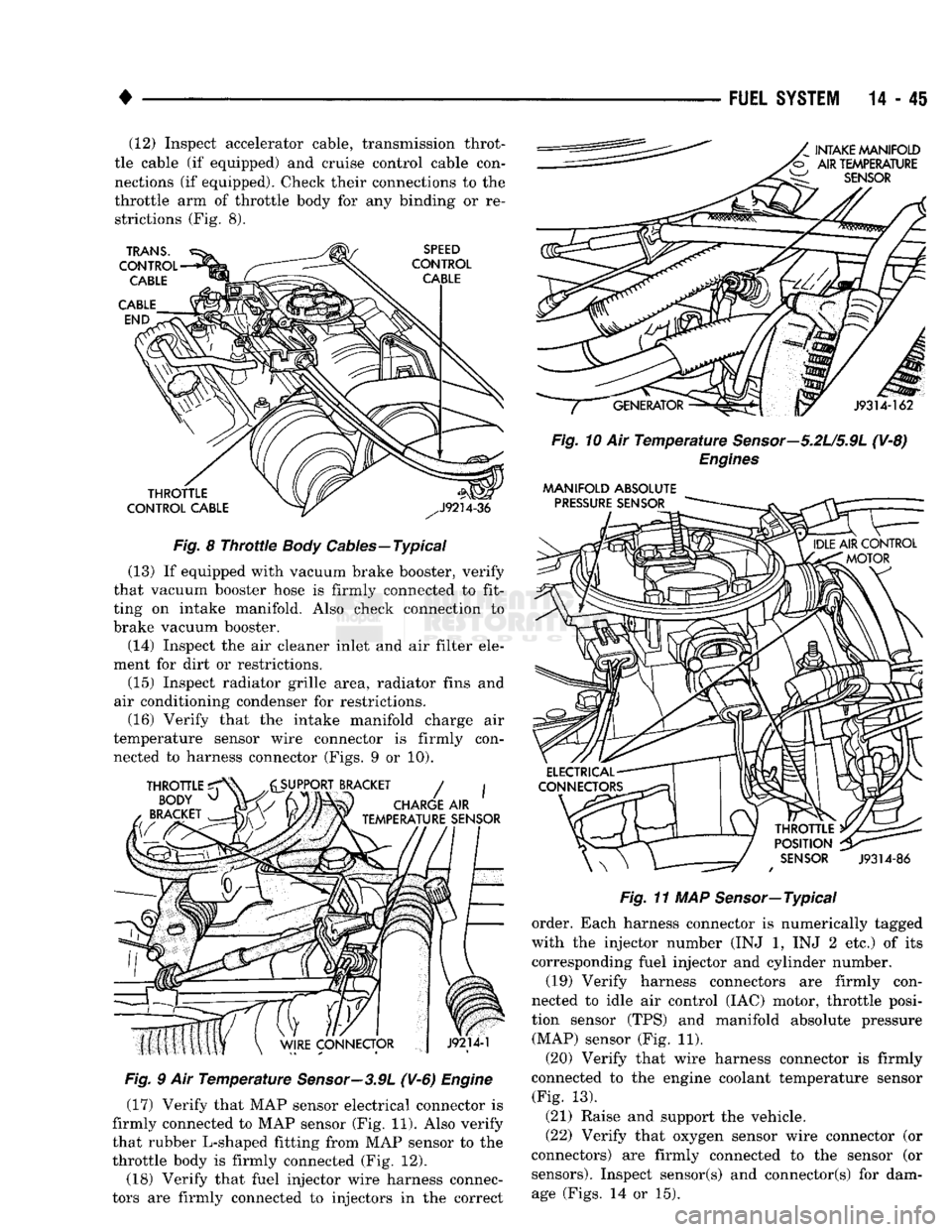
14-45 (12) Inspect accelerator cable, transmission throt
tle cable (if equipped) and cruise control cable con
nections (if equipped). Check their connections to the
throttle arm of throttle body for any binding or re strictions (Fig. 8).
Fig.
8
Throttle
Body
Cables—Typical
(13) If equipped with vacuum brake booster, verify
that vacuum booster hose is firmly connected to fit
ting on intake manifold. Also check connection to
brake vacuum booster.
(14) Inspect the air cleaner inlet and air filter ele
ment for dirt or restrictions.
(15) Inspect radiator grille area, radiator fins and
air conditioning condenser for restrictions. (16) Verify that the intake manifold charge air
temperature sensor wire connector is firmly con nected to harness connector (Figs. 9 or 10).
Fig.
9 Air
Temperature
Sensor—3.9L
(V-6)
Engine
(17) Verify that MAP sensor electrical connector is
firmly connected to MAP sensor (Fig. 11). Also verify
that rubber L-shaped fitting from MAP sensor to the
throttle body is firmly connected (Fig. 12).
(18) Verify that fuel injector wire harness connec
tors are firmly connected to injectors in the correct
Fig.
10 Air
Temperature
Sensor—5.2U5.9L
(V-8)
Engines
MANIFOLD
ABSOLUTE
Fig.
11 MAP Sensor—Typical
order. Each harness connector is numerically tagged
with the injector number (INJ 1, INJ 2 etc.) of its
corresponding fuel injector and cylinder number.
(19) Verify harness connectors are firmly con
nected to idle air control (IAC) motor, throttle posi
tion sensor (TPS) and manifold absolute pressure (MAP) sensor (Fig. 11).
(20) Verify that wire harness connector is firmly
connected to the engine coolant temperature sensor (Fig. 13).
(21) Raise and support the vehicle.
(22) Verify that oxygen sensor wire connector (or
connectors) are firmly connected to the sensor (or sensors). Inspect sensor(s) and connector(s) for damage (Figs. 14 or 15).
Page 898 of 1502
•
FUEL SYSTEM
14-79
OVERDRIVE/OVERRIDE SWITCH-PCM
INPUT
The overdrive/override switch is not used with
manual transmissions. On vehicles equipped with overdrive, the PCM reg
ulates the 3-4 overdrive upshift and downshift
through the overdrive solenoid. An override switch is located on the instrument panel. The overdrive/override switch is a momentary con
tact switch. The switch contacts are normally open. When the switch is activated, the PCM will receive a ground signal. The transmission will not enter over
drive when the operator presses the override switch.
The transmission downshifts if the operator presses
the override switch while in overdrive.
COOLANT TEMPERATURE SENSOR The coolant temperature sensor is not used with
manual transmissions.
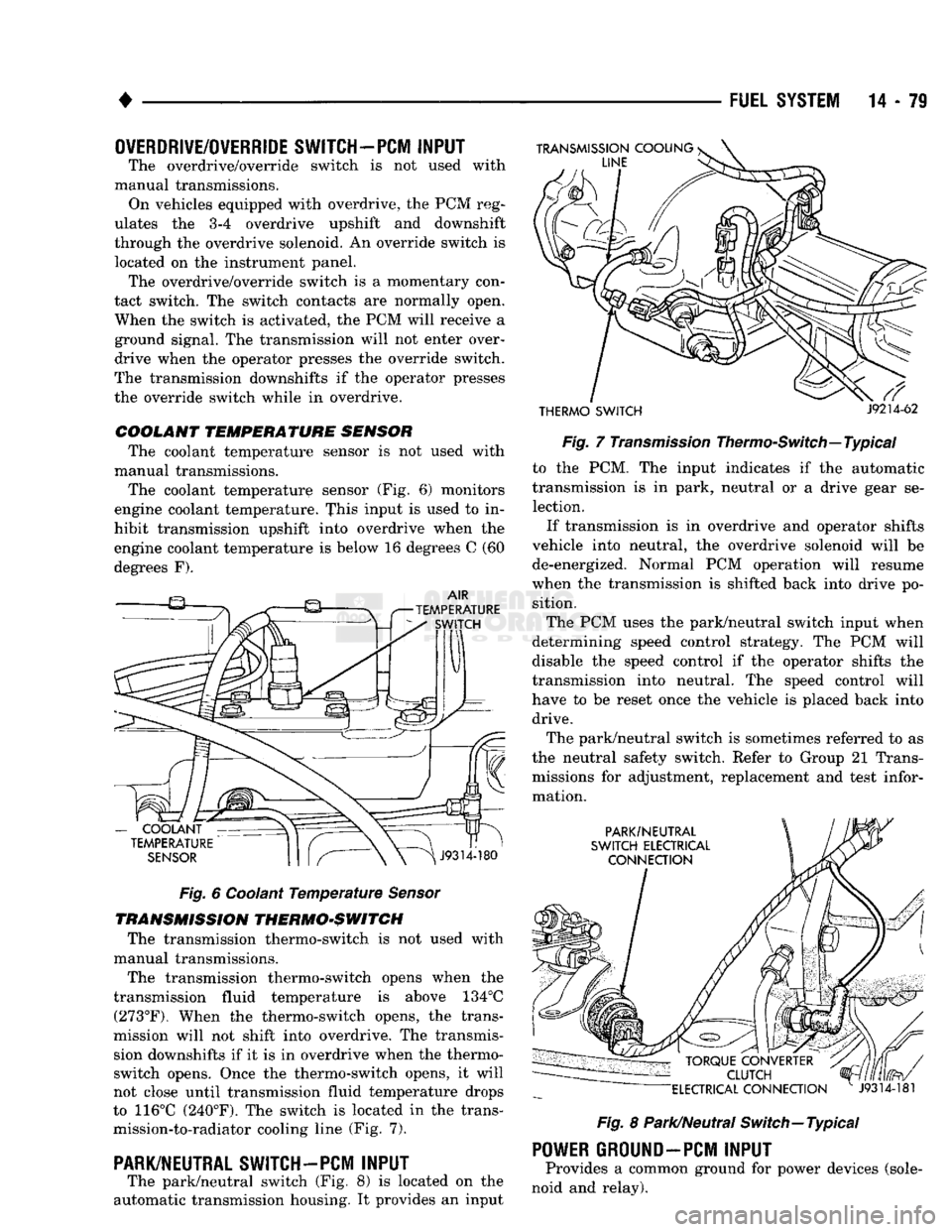
The coolant temperature sensor (Fig. 6) monitors
engine coolant temperature. This input is used to in
hibit transmission upshift into overdrive when the
engine coolant temperature is below 16 degrees C (60
degrees F).
Fig.
6 Coolant
Temperature
Sensor
TRANSMISSION THERMO-SWITCH The transmission thermo-switch is not used with
manual transmissions.
The transmission thermo-switch opens when the
transmission fluid temperature is above 134°C (273°F). When the thermo-switch opens, the trans
mission will not shift into overdrive. The transmis sion downshifts if it is in overdrive when the thermo-
switch opens. Once the thermo-switch opens, it will
not close until transmission fluid temperature drops
to 116°C (240°F). The switch is located in the trans mission-to-radiator cooling line (Fig. 7).
PARK/NEUTRAL SWITCH-PCM
INPUT
The park/neutral switch (Fig. 8) is located on the
automatic transmission housing. It provides an input
THERMO SWITCH
J9214-62
Fig.
7
Transmission
Thermo-Switch—Typical to the PCM. The input indicates if the automatic
transmission is in park, neutral or a drive gear se lection.
If transmission is in overdrive and operator shifts
vehicle into neutral, the overdrive solenoid will be de-energized. Normal PCM operation will resume
when the transmission is shifted back into drive po sition.
The PCM uses the park/neutral switch input when
determining speed control strategy. The PCM will
disable the speed control if the operator shifts the
transmission into neutral. The speed control will
have to be reset once the vehicle is placed back into drive.
The park/neutral switch is sometimes referred to as
the neutral safety switch. Refer to Group 21 Trans missions for adjustment, replacement and test infor
mation.
Fig.
8 Park/Neutral Switch—Typical
POWER
GROUND-PCM
INPUT
Provides a common ground for power devices (sole
noid and relay).