1993 DODGE TRUCK radiator
[x] Cancel search: radiatorPage 309 of 1502
7 - 38
COOLING
SYSTEM
•
WARNING:
DO NOT
ATTEMPT
TO
BEND
OR
STRAIGHTEN
FAN
BLADES
IF
NOT WITHIN
SPECI
FICATIONS.
(4) Inspect fan assembly for cracks, bends, loose
rivets or broken welds. Replace fan if any damage is
found.
CAUTION; If the fan
blade assembly
is
replaced
be
cause
of
mechanical damage,
the fan
pulley
and
viscous
fan
drive should also
be
inspected.
These
components
could have been damaged
due to ex
cessive
vibration.
INSTALLATION
(1) Install fan blade assembly to viscous fan drive.
Tighten mounting bolts.
(2) Position the fan shroud and fan blade/viscous
fan drive to the vehicle as an assembly.
(3) Install viscous fan drive assembly on fan hub
shaft. Tighten mounting nut to 57 N*m (42 ft. lbs.)
torque.
(4) Install fan shroud bolts.
(5) Install battery cable to battery.
VISCOUS
FAN
DRIVE
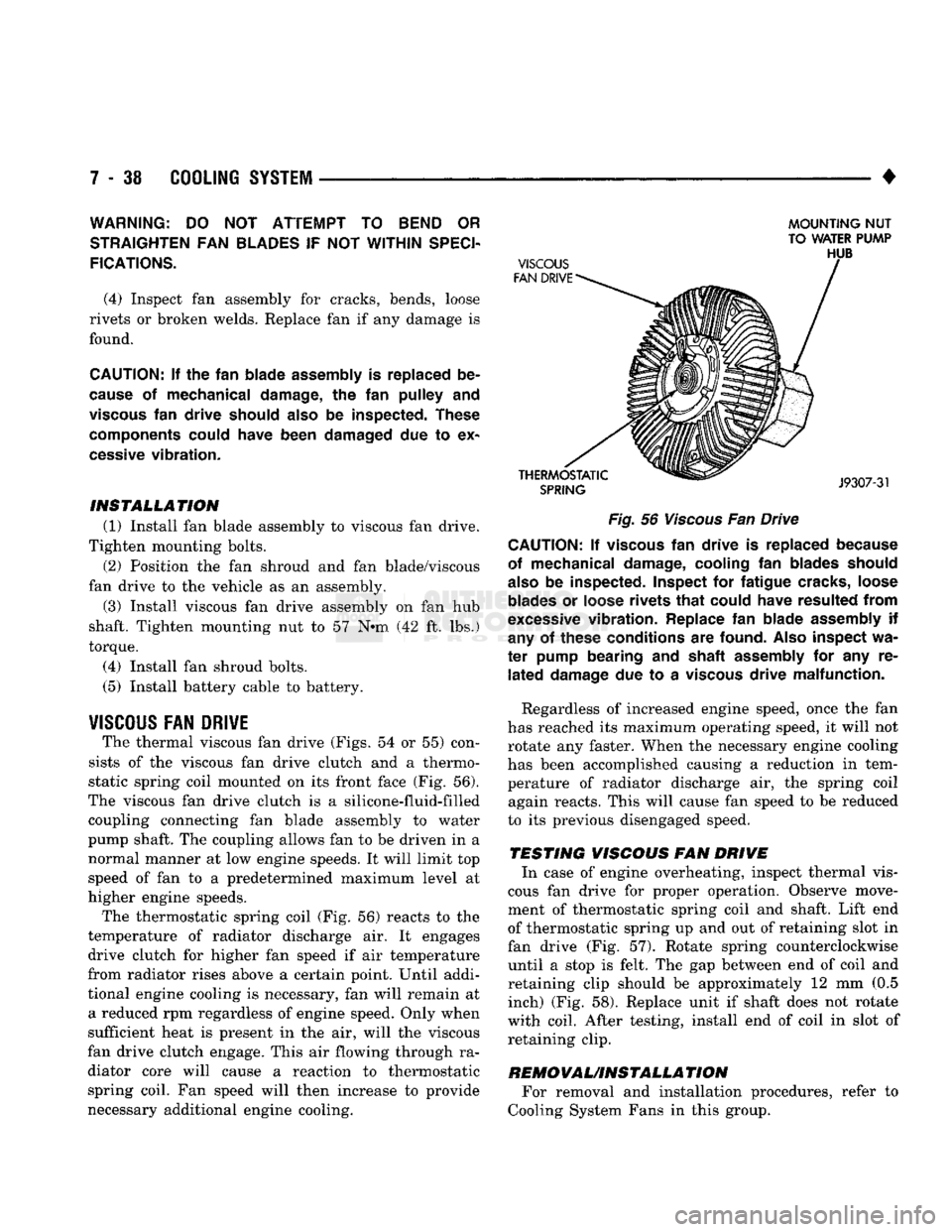
The thermal viscous fan drive (Figs. 54 or 55) con
sists of the viscous fan drive clutch and a thermo
static spring coil mounted on its front face (Fig. 56).
The viscous fan drive clutch is a silicone-fluid-filled coupling connecting fan blade assembly to water
pump shaft. The coupling allows fan to be driven in a normal manner at low engine speeds. It will limit top
speed of fan to a predetermined maximum level at
higher engine speeds.
The thermostatic spring coil (Fig. 56) reacts to the
temperature of radiator discharge air. It engages drive clutch for higher fan speed if air temperature
from radiator rises above a certain point. Until addi
tional engine cooling is necessary, fan will remain at a reduced rpm regardless of engine speed. Only when
sufficient heat is present in the air, will the viscous
fan drive clutch engage. This air flowing through ra diator core will cause a reaction to thermostatic spring coil. Fan speed will then increase to provide
necessary additional engine cooling.
MOUNTING
NUT
TO WATER PUMP
Fig.
56
Viscous
Fan Drive CAUTION; If
viscous
fan
drive
is
replaced because
of mechanical damage, cooling
fan
blades should
also
be
inspected. Inspect
for
fatigue cracks, loose
blades
or
loose rivets
that
could have resulted
from
excessive
vibration. Replace
fan
blade assembly
if
any
of
these conditions
are
found.
Also
inspect
wa
ter
pump bearing
and
shaft assembly
for any re
lated
damage
due to a
viscous
drive malfunction.
Regardless of increased engine speed, once the fan
has reached its maximum operating speed, it will not
rotate any faster. When the necessary engine cooling
has been accomplished causing a reduction in tem perature of radiator discharge air, the spring coil again reacts. This will cause fan speed to be reduced
to its previous disengaged speed.
TESTING VISCOUS FAN DRIVE In case of engine overheating, inspect thermal vis
cous fan drive for proper operation. Observe move
ment of thermostatic spring coil and shaft. Lift end
of thermostatic spring up and out of retaining slot in
fan drive (Fig. 57). Rotate spring counterclockwise until a stop is felt. The gap between end of coil and
retaining clip should be approximately 12 mm (0.5 inch) (Fig. 58). Replace unit if shaft does not rotate
with coil. After testing, install end of coil in slot of retaining clip.
REMOVAUINSTALLA
TION For removal and installation procedures, refer to
Cooling System Fans in this group.
Page 319 of 1502
7
- 48
COOLING
SYSTEM
•
ENGINE BLOCK HEATERS
GENERAL
INFORMATION
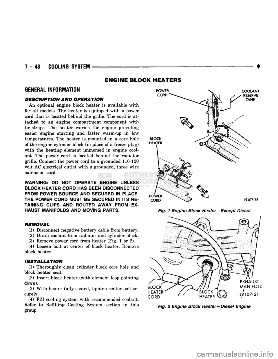
DESCRIPTION AND OPERATION An optional engine block heater
is
available with
for
all
models. The heater
is
equipped with
a
power
cord that
is
located behind the grille. The cord
is at
tached
to an
engine compartment component with
tie-straps.
The
heater warms
the
engine providing easier engine starting
and
faster warm-up
in low
temperatures. The heater
is
mounted
in a
core hole of the engine cylinder block (in place of
a
freeze plug)
with
the
heating element immersed
in
engine cool ant.
The
power cord
is
located behind
the
radiator
grille. Connect the power cord
to a
grounded 110-120
volt AC electrical outlet with
a
grounded, three wire
extension cord.
WARNING:
DO NOT
OPERATE ENGINE
UNLESS
BLOCK
HEATER
CORD
HAS
BEEN
DISCONNECTED
FROM POWER
SOURCE
AND
SECURED
IN
PLACE.
THE POWER
CORD
MUST BE
SECURED
IN ITS RE
TAINING
CLIPS
AND ROUTED AWAY FROM
EX
HAUST MANIFOLDS AND MOVING
PARTS.
REMOVAL
(1) Disconnect negative battery cable from battery.
(2) Drain coolant from radiator and cylinder block.
(3) Remove pow^r cord from heater (Fig.
1 or 2).
(4)
Loosen bolt
at
center
of
block heater. Remove
block heater.
INSTALLATION (1) Thoroughly clean cylinder block core hole
and
block heater seat. (2) Insert block heater (with element loop pointing
down).
(3) With heater fully seated, tighten center bolt se
curely.
(4)
Fill cooling system with recommended coolant.
Refer
to
Refilling Cooling System section
in
this
group.
Fig.
1
Engine
Block
Heater—Except
Diesel
Fig.
2
Engine
Block
Heater—Diesel
Engine
Page 320 of 1502
SPECIFICATIONS
GENERAL
INFORMATION
The following specifications are published from the
latest information available at the time of publica
tion. If anything differs between the specifica
tions found on the Vehicle Emission Control
Information (VECI) label and the following spec
ifications, use specifications on VECI label. The
VECI label is located in the engine compartment.
DRIVE
BELT
TENSION
All engines are equipped with a spring loaded au
tomatic belt tensioner. Do not attempt to check belt
tension with a belt tension gauge on vehicles
equipped with an automatic belt tensioner. Refer to
Automatic Belt Tensioner in this group.
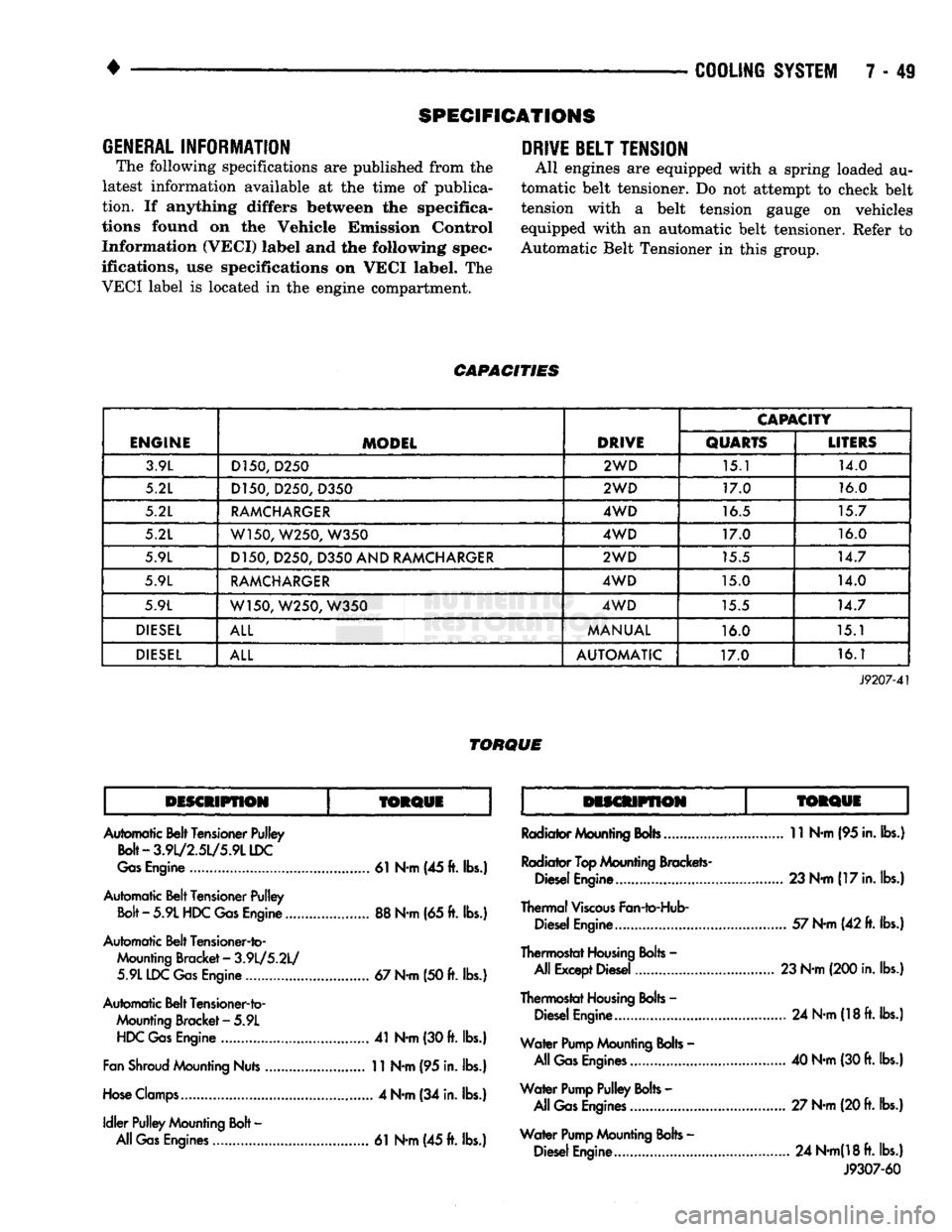
CAPACITIES
ENGINE
MODEL
DRIVE
CAPACITY
ENGINE
MODEL
DRIVE
QUARTS
LITERS
3.9L D150,
D250
2WD
15.1 14.0
5.2L D150, D250,
D350
2WD
17.0 16.0
5.2L
RAMCHARGER
4WD
16.5 15.7
5.2L W150, W250,
W350
4WD
17.0 16.0
5.9L D150, D250,
D350
AND
RAMCHARGER
2WD
15.5 14.7
5.9L
RAMCHARGER
4WD
15.0 14.0
5.9L W150, W250,
W350
4WD
15.5 14.7
DIESEL
ALL
MANUAL
16.0 15.1
DIESEL
ALL
AUTOMATIC
17.0 16.1
J9207-41
TORQUE
DISCMPflON
TORQUE
TORQUi
Automatic Belt Tensioner Pulley
Bolt-3.9l/2.5L/5.9LLDC
Gas
Engine
61
N-m (45
ft.
lbs.)
Automatic Belt Tensioner Pulley
Bolt
-
5.9L
HDC
Gas
Engine
88
N-m
(65
ft.
lbs.)
Automatic Belt Tensioner-to- Mounting Bracket
-
3.9L/5.2L/ 5.9L IDC
Gas
Engine
67
N-m
(50
ft.
lbs.)
Automatic Belt Tensioner-to- Mounting Bracket
-
5.9L
HDC
Gas
Engine
41
N-m
(30
ft.
lbs.)
Fan
Shroud
Mounting Nuts
11
N-m
(95
in. lbs.)
Hose
Clamps
4
N-m
(34
in. lbs.)
Idler
Pulley Mounting
Bolt
-
All
Gas
Engines
61
N-m
(45
ft.
lbs.)
Radiator Mounting
Bobs
11
N-m
(95
in. lbs.)
Radiator
Top
Mounting Brackets- Diesel Engine...... 23 N-m
(17
in. lbs.)
Thermal
Viscous
Fan-to-Hub- Diesel Engine
57
N-m
(42
ft.
lbs.)
Thermostat
Housing
Bolts
-
All Except Diesel 23 N-m (200 in. lbs.)
Thermostat
Housing
Bolts
-
Diesel Engine
24
N-m
(18
ft.
lbs.)
Water
Pump
Mounting
Bolts
-
All
Gas
Engines
40
N-m
(30
ft.
lbs.)
Water
Pump
Pulley
Bolts
-
All
Gas
Engines
27 N-m (20
ft.
lbs.)
Water
Pump
Mounting
Bolts
-
Diesel Engine
24
N-m(18ft.
lbs.) J9307-60
Page 414 of 1502
•
HORNS
8G - 3
SERVICE
PROCEDURES
HORN
SWITCH (HORN PAD ASSEMBLY)
REPLACEMENT
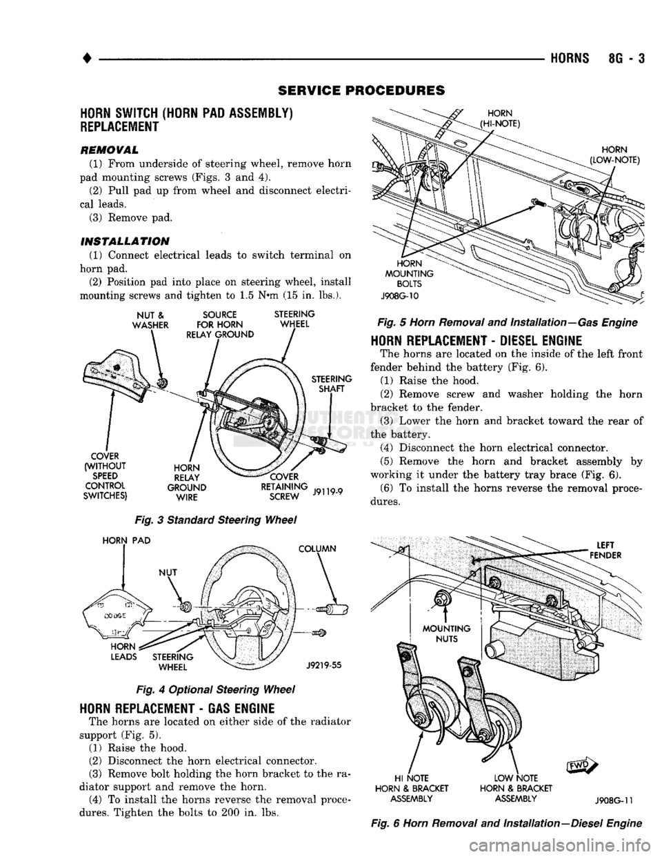
REMOVAL (1) From underside of steering wheel, remove horn
pad mounting screws (Figs. 3 and 4). (2) Pull pad up from wheel and disconnect electri
cal leads. (3) Remove pad.
INSTALLATION
(1) Connect electrical leads to switch terminal on
horn pad. (2) Position pad into place on steering wheel, install
mounting screws and tighten to 1.5 N*m (15 in. lbs.).
NUT
&
WASHER
SOURCE
FOR HORN
RELAY GROUND STEERING
WHEEL
STEERING SHAFT
COVER
(WITHOUT
SPEED
CONTROL
SWITCHES) HORN
RELAY
GROUND WIRE COVER
RETAINING
SCREW
J9119-9
Fig.
3 Standard Steering
Wheel
HORN
PAD
COLUMN
HORN
LEADS
STEERING WHEEL
J9219-55
Fig.
4 Optional Steering
Wheel
HORN
REPLACEMENT
-
GAS ENGINE
The horns are located on either side of the radiator
support (Fig. 5). (1) Raise the hood.
(2) Disconnect the horn electrical connector.
(3) Remove bolt holding the horn bracket to the ra
diator support and remove the horn. (4) To install the horns reverse the removal proce
dures.
Tighten the bolts to 200 in. lbs.
HORN
(HI-NOTE)
HORN
(LOW-NOTE)
HORN
MOUNTING
BOLTS
J908G-10
Fig.
5
Horn
Removal
and Installation—Gas
Engine
HORN
REPLACEMENT
-
DIESEL ENGINE
The horns are located on the inside of the left front
fender behind the battery (Fig. 6). (1) Raise the hood.
(2) Remove screw and washer holding the horn
bracket to the fender. (3) Lower the horn and bracket toward the rear of
the battery. (4) Disconnect the horn electrical connector.
(5) Remove the horn and bracket assembly by
working it under the battery tray brace (Fig. 6). (6) To install the horns reverse the removal proce
dures.
LEFT
FENDER
HI NOTE
HORN
&
BRACKET
ASSEMBLY
LOW NOTE
HORN
&
BRACKET
ASSEMBLY
J908G-11
Fig.
6
Horn
Removal
and Installation—Diesel
Engine
Page 546 of 1502
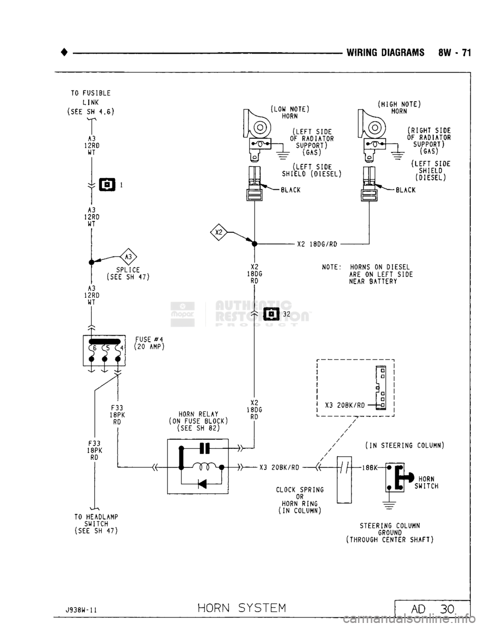
WIRING DIAGRAMS
8W - 71
TO FUSIBLE
LINK
(SEE
SH 4,6)
:X2
SPLICE
(SEE
SH 47)
FUSE
#4
(20 AMP)
F33
18PK
RD
F33
18PK
RD
HORN RELAY
[ON
FUSE BLOCK)
(SEE
SH 82)
TO HEADLAMP SWITCH
(SEE
SH 47)
LOW NOTE)
HORN
(HIGH
NOTE)
HORN
(LEFT
SIDE
OF RADIATOR SUPPORT) (GAS)
(LEFT
SIDE
SHIELD (DIESEL)
BLACK X2 18DG/RD
(RIGHT
SIDE
OF RADIATOR SUPPORT) (GAS)
(LEFT
SIDE SHIELD
(DIESEL) BLACK
X2
18DG
RD
NOTE:
HORNS
ON
DIESEL
ARE
ON
LEFT SIDE
NEAR BATTERY
32
X2
18DG
RD
X3
20BK/RD
CLOCK SPRING
OR
HORN RING
(IN
COLUMN)
(IN
STEERING COLUMN)
HORN
SWITCH
STEERING
COLUMN
GROUND
(THROUGH CENTER SHAFT)
J938W-11
HORN
SYSTEM
AD
30
Page 559 of 1502
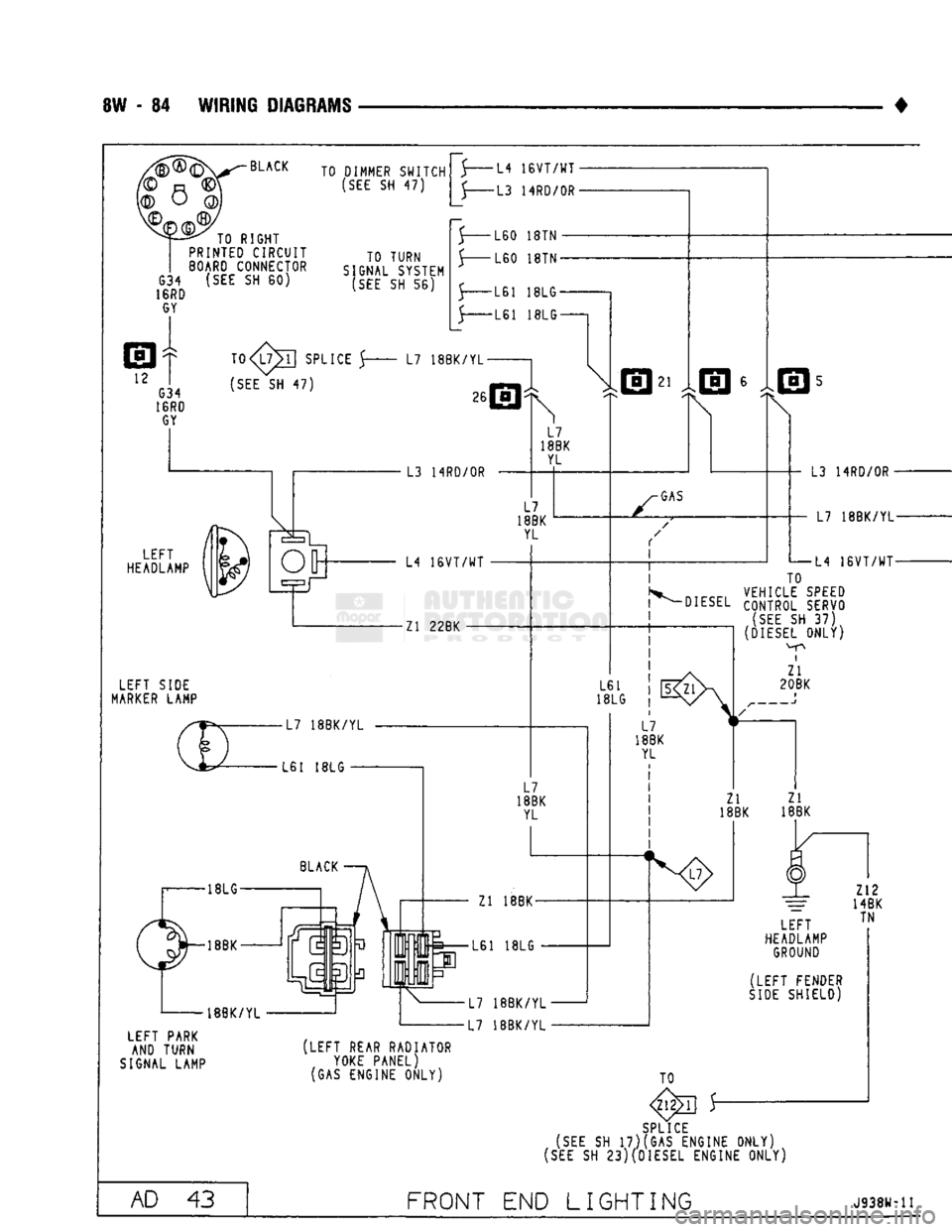
8W
- 84
WIRING DIAGRAMS
BLACK TO RIGHT
PRINTEO CIRCUIT
BOARD
CONNECTOR
G34
(SEE SH 60)
16RD
GY
TO DIMMER SWITCH
(SEE
SH 47)
TO TURN
SIGNAL SYSTEM
(SEE
SH 56)
T0
5 L7
18BK/YL-
(SEE
SH 47)
LEFT
HEADLAMP
LEFT SIDE
MARKER
LAMP LEFT PARK
AND TURN
SIGNAL LAMP •L4
16VT/WT
-L3 14RD/0R-
•L60
18TN •
•L60
18TN-
-L61
18LG-
-L61
18LG-
26 L3 14RD/0R L7
I8BK
YL
L7
18BK YL L4
16VT/WT
Zl
22BK 21
GAS
L61
18LG L3 14RD/0R
-
• L7
18BK/YL- 5
TO
ntrrr,
VEHICLE
SPEED
DIESEL
CONTROL SERVO
(SEE
SH 37)
(DIESEL
ONLY)
i
Zl
20BK
L7
18BK YL
Zl 18BK-
L61
18LG
L7 18BK/YL
L7 18BK/YL L7
18BK YL
Zl Zl
18BK
18BK
N8>
LEFT
HEADLAMP
GROUND
(LEFT FENDER
SIDE
SHIELD) Z12
14BK TN
[LEFT
REAR RADIATOR
YOKE
PANEL)
(GAS ENGINE ONLY) TO
SPLICE
(SEE
SH
17)(GAS ENGINE ONLY)
(SEE
SH
23)(DIESEL ENGINE ONLY)
AD
43
FRONT
END
LIGHTING
J938W-11
Page 560 of 1502
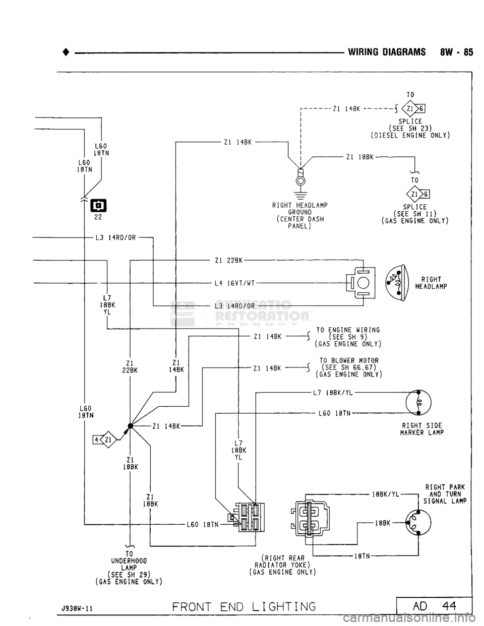
•
WIRING
DIAGRAMS
8W - 85 L60
18TN
L60
18TN
22
-L3 14RD/0R
L7
18BK YL Zl
22BK
L60
18TN Zl 14BK Zl 14BK
TO
SPLICE
(SEE
SH 23)
(DIESEL
ENGINE
ONLY)
Zl 18BK-
TO
RIGHT
HEADLAMP GROUND
(CENTER DASH PANEL)
SPLICE
(SEE
SH 11)
(GAS ENGINE
ONLY)
Zl
22BK
L4
16VT/WT-
L3 14RD/0R 3d
RIGHT
HEADLAMP Zl 14BK
Zl 14BK f TO ENGINE WIRING
-j (SEE SH 9) (GAS ENGINE
ONLY)
„ TO BLOWER MOTOR
A (SEE SH
66,67)
(GAS ENGINE
ONLY)
RIGHT
SIDE
MARKER
LAMP
RIGHT
PARK AND TURN
SIGNAL LAMP
TO
UNDERHOOD
LAMP
(SEE
SH 29)
(GAS ENGINE
ONLY)
(RIGHT
REAR
RADIATOR YOKE)
(GAS ENGINE
ONLY)
-18TN-
J938W-11
FRONT
END LIGHTING
AD
44
Page 561 of 1502
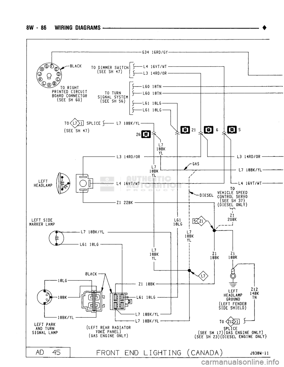
8W - 86 WIRING DIAGRAMS
-G34 16RD/GY-
•BLACK
Q>
V© Q
TO RIGHT
PRINTED
CIRCUIT
BOARD
CONNECTOR
(SEE
SH 60) TO DIMMER SWITCH
(SEE
SH 47)
TO TURN
SIGNAL SYSTEM
(SEE
SH 56) •L4
16VT/WT
•
-L3 14RD/0R-LEFT
HEADLAMP
LEFT SIDE
MARKER
LAMP LEFT PARK
AND TURN
SIGNAL LAMP 5-
-L60 18TN
•L60
18TN-
-L61 18LG-
-L61 18LG-
TO
SPLICE 5 L7 18BK/YL-
(SEE
SH 47) | 26
L3 14RD/0R L7
18BK YL
L7
18BK YL L4
16VT/WT
Zl 22BK
21
GAS
I
L3 14RD/OR-
• L7 18BK/YL-
-L4 16VT/WT- L61 j |5
VEHICLE
SPEED
l DIESEL CONTROL SERVO
! (SEE SH 37)
DIESEL
ONLY)
i
Zl
20BK 18LG
L7
18BK YL Zl 18BK-
L61 18LG
L7 18BK/YL
L7 18BK/YL I
i
L7
18BK
YL
Zl
18BK LEFT
HEADLAMP
GROUND
(LEFT FENDER
SIDE
SHIELD) Z12
14BK TN (LEFT REAR RADIATOR
YOKE
PANEL)
(GAS ENGINE ONLY) TO
SPLICE
(SEE
SH
17)(GAS
ENGINE
ONLY)
4
(SEE
SH
23)(DIESEL
ENGINE
ONLY)
AD 45 FRONT END LIGHTING (CANADA)
Jsaew-n