1993 DODGE TRUCK radiator
[x] Cancel search: radiatorPage 682 of 1502
5.9L
ENGINE SERVICE PROCEDURES
INDEX
page
Camshaft
91
Crankshaft
98
Crankshaft Main Bearings
99
Crankshaft Rear
Oil
Seals
100
Cylinder
Block
101
Cylinder
Head Cover
81
Cylinder
Heads
82
Distributor
92
Engine Assembly
80
Engine
Front
Mounts
77
Engine Rear Mount
78
Front
Crankshaft
Oil
Seal Replacement
91
page
General
Information
77
Hydraulic
Tappets
87
Oil
Pan 93
Oil Pump
. 94
Piston
/
Connecting
Rod
Assembly
96
Rocker Arms
81
Specifications—5.9L
Engine
103
Timing
Chain Cover
89
Valve Stem Shield
/
Spring Replacement
86
Valve
Timing
. 88
Valves
/
Valve Springs
84
Vibration
Damper
88
GENERAL
INFORMATION
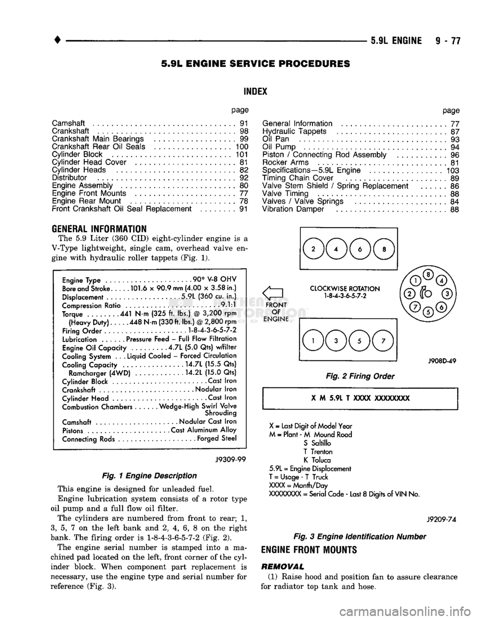
The 5.9 Liter (360 CID) eight-cylinder engine is a
V-Type lightweight, single cam, overhead valve en
gine with hydraulic roller tappets (Fig. 1).
Engine Type .90° V-8 OHV
Bore and Stroke 101.6 x 90.9
mm
(4.00 x 3.58 in.)
Displacement 5.9L (360 cu. in.)
Compression Ratio 9.1:1
Torque 441 N-m (325 ft. lbs.) @ 3,200 rpm (Heavy Duty). 448 N-m (330 ft. lbs.)
@
2,800 rpm
Firing Order
1-8-4-3-6-5-7-2
Lubrication ...... Pressure Feed - Full Flow Filtration
Engine Oil Capacity .4.7L (5.0 Qts) w/filter
Cooling System . .
.
Liquid Cooled - Forced Circulation Cooling Capacity ..... . . 14.7L (15.5 Qts)
Ramcharger (4WD) 14.2L (15.0 Qts)
Cylinder Block Cast Iron Crankshaft
-
Nodular Iron
Cylinder Head • . Cast Iron Combustion Chambers Wedge-High Swirl Valve
Shrouding
Camshaft Nodular Cast Iron Pistons Cast Aluminum Alloy
Connecting Rods Forged Steel
J9309-99
Fig. 1
Engine
Description
This engine is designed for unleaded fuel.
Engine lubrication system consists of a rotor type
oil pump and a full flow oil filter.
The cylinders are numbered from front to rear; 1,
3,
5, 7 on the left bank and 2, 4, 6, 8 on the right
bank. The firing order is
1-8-4-3-6-5-7-2
(Fig. 2).
The engine serial number is stamped into a ma
chined pad located on the left, front corner of the cyl
inder block. When component part replacement is
necessary, use the engine type and serial number for
reference (Fig. 3).
o
FRONT OF
ENGINE CLOCKWISE ROTATION
1-8-4-3-6-5-7-2
J908D-49
Fig. 2 Firing Order
X
M 5.9L T
XXXX
XXXXXXXX
X
= Last Digit of Model Year
M = Plant - M Mound Road S Saltillo
T Trenton K Toluca
5.9L = Engine Displacement
T
= Usage -
T
Truck
XXXX
= Month/Day
XXXXXXXX
= Serial Code - Last 8 Digits of
VIN
No.
J9209-74
Fig.
3
Engine
identification
Number
ENGINE
FRONT MOUNTS
REMOVAL (1) Raise hood and position fan to assure clearance
for radiator top tank and hose.
Page 685 of 1502
9
- 80 5.9L
ENGINE
•
TRANSFER
CASE
TRANSFER
CASE
ENGINE REAR
SUPPORT
PLATE
INSULATOR
MOUNTING
PLATE
LOWER
INSULATOR
\7"
RAIL
1
J9109-244
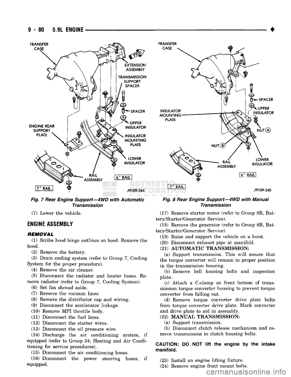
Fig.
7 Rear
Engine
Support—4WD
with
Automatic
Transmission
(7) Lower the vehicle.
ENGINE
ASSEMBLY
REMOVAL
(1) Scribe hood hinge outlines on hood. Remove the
hood. (2) Remove the battery.
(3) Drain cooling system (refer to Group 7, Cooling
System for the proper procedure). (4) Remove the air cleaner.
(5) Disconnect the radiator and heater hoses. Re
move radiator (refer to Group 7, Cooling System). (6) Set fan shroud aside.
(7) Remove the vacuum lines.
(8) Remove the distributor cap and wiring.
(9) Disconnect the accelerator linkage.
(10) Remove MPI throttle body.
(11) Disconnect the fuel lines.
(12) Disconnect the starter wires.
(13) Disconnect the oil pressure wire.
(14) Discharge the air conditioning system, if
equipped (refer to Group 24, Heating and Air Condi
tioning for service procedures).
(15) Disconnect the air conditioning hoses.
(16) Disconnect the power steering hoses, if
equipped.
INSULATOR
MOUNTING
PLATE
SPACER
UPPER
INSULATOR
NUT®
LOWER
INSULATOR
J9109-245
Fig.
8 Rear
Engine
Support—4WD
with
Manual
Transmission
(17) Remove starter motor (refer to Group 8B, Bat
tery/Starter/Generator Service).
(18) Remove the generator (refer to Group 8B, Bat
tery/Starter/Generator Service).
(19) Raise and support the vehicle on a hoist.
(20) Disconnect exhaust pipe at manifold.
(21) AUTOMATIC TRANSMISSION: (a) Support transmission. This will assure that
the torque converter will remain in proper position in the transmission housing. (b) Remove bell housing bolts and inspection
plate. (c) Attach a C-clamp on front bottom of trans
mission torque converter housing to prevent torque converter from falling out. (d) Remove torque converter drive plate bolts
from torque converter drive plate. Mark converter and drive plate to aid in assembly.
(22) MANUAL TRANSMISSION; (a) Support transmission.
(b) Disconnect clutch release mechanism and re
move transmission to clutch housing bolts.
CAUTION:
manifold.
DO
NOT
lift
the engine by the intake
(23) Install an engine lifting fixture.
(24) Remove engine front mount bolts.
Page 686 of 1502
•
5.9L ENGINE
9-81 (25) Lower the vehicle.
(26) On automatic transmission vehicles, discon
nect the engine from the torque converter drive
plate. On manual transmission vehicles, move engine forward until drive pinion shaft clears the clutch
disc.
Remove engine from engine compartment.
(27) Install engine assembly on engine repair
stand.
INSTALLATION (1) Remove engine from the repair stand and posi
tion in the engine compartment.
(2) Install an engine support fixture.
(3) Raise and support the vehicle on a hoist.
(4)
AUTOMATIC TRANSMISSION: (a) Position the torque converter and drive plate.
Install torque converter drive plate bolts. Tighten
the bolts to 31 Nnn (270 in. lbs.) torque.
(b) Install the engine front mounts.
(c) Install bell housing bolts. Tighten the bolts to
41 Nnn (30 ft. lbs.) torque.
(d) Remove C-clamp.
(e) Install the inspection plate.
(5)
MANUAL TRANSMISSION: (a) Position the drive pinion shaft to the clutch
disc.
(b) Connect the clutch release mechanism and
install the transmission to clutch bolts. Tighten the
bolts to 68 Nnn (50 ft. lbs.) torque.
(c) Install the engine front mounts.
(6) Remove transmission support.
(7) Install exhaust pipe to manifold. (8) Lower the vehicle.
(9) Remove engine lifting fixture.
(10) Install the generator (refer to Group 8B, Bat
tery/Starter/Generator Service). (11) Install the starter motor (refer to Group 8B,
Battery/Starter/Generator Service).
(12) Connect power steering hoses, if so equipped.
(13) Connect air conditioning hoses.
(14) Evacuate and charge the air conditioning sys
tem, if equipped (refer to Group 24, Heater and Air Conditioning for service procedures).
(15) Using a new gasket, install MPI throttle body.
Tighten the throttle body bolts to 23 Nnn (200 in. lbs.) torque.
(16) Connect the accelerator linkage. (17) Connect the starter wires.
(18) Connect the oil pressure wire.
(19) Install the distributor cap and wiring.
(20) Connect the vacuum lines.
(21) Connect the fuel lines.
(22) Install the radiator (refer to Group 7, Cooling
System). Connect the radiator hoses and heater
hoses.
(23) Install fan shroud in position.
(24) Fill cooling system (refer to Group 7, Cooling
System for the proper procedure). (25) Install the air cleaner.
(26) Install the battery.
(27) Warm engine and adjust.
(28) Install hood and line up with the scribe
marks. (29) Road test vehicle.
CYLINDER HEAD COVER
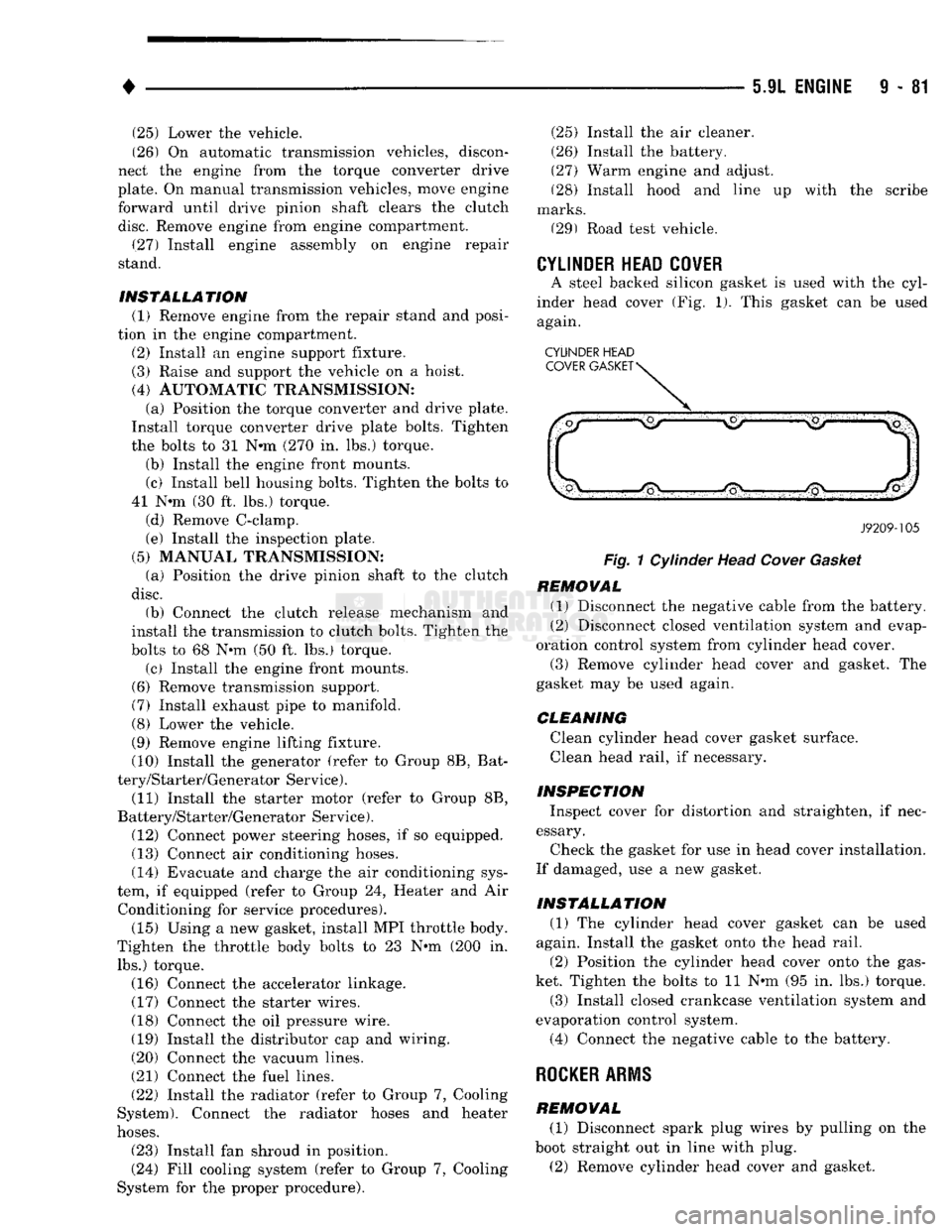
A steel backed silicon gasket is used with the cyl
inder head cover (Fig. 1). This gasket can be used
again.
CYLINDER HEAD
J9209-105
Fig.
1 Cylinder Head
Cover
Gasket
REMOVAL (1) Disconnect the negative cable from the battery.
(2) Disconnect closed ventilation system and evap
oration control system from cylinder head cover.
(3) Remove cylinder head cover and gasket. The
gasket may be used again.
CLEANING
Clean cylinder head cover gasket surface.
Clean head rail, if necessary.
INSPECTION Inspect cover for distortion and straighten, if nec
essary.
Check the gasket for use in head cover installation.
If damaged, use a new gasket.
INSTALLATION (1) The cylinder head cover gasket can be used
again. Install the gasket onto the head rail.
(2) Position the cylinder head cover onto the gas
ket. Tighten the bolts to 11 Nnn (95 in. lbs.) torque. (3) Install closed crankcase ventilation system and
evaporation control system.
(4) Connect the negative cable to the battery.
ROCKER
ARMS
REMOVAL (1) Disconnect spark plug wires by pulling on the
boot straight out in line with plug.
(2) Remove cylinder head cover and gasket.
Page 712 of 1502
•
5.9L
(DIESEL)
ENGINE
9 -
107
5.9L
(DIESEL)
ENGINE
SERVICE
PROCEDURES
INDEX
page
Camshaft
127
Crankshaft
138
Cylinder
Block
129
Cylinder
Head
113
Engine
Assembly
. 109
Engine
Front
Mounts
(Insulators
/
Brackets)
... 107
Engine
Rear Support
108
Gear
Housing
/
Cover
122
General
Information
107
Oil Cooler Element
/
Gasket
. 149
Oil
Filter
148
page
Oil
Filter
Bypass
Valve
. 148
Oil Pan
/
Suction Tube
146
Oil Pressure Regulator Valve
/
Spring
148
Oil Pump
146
Piston
/
Connecting
Rod
Assembly
134
Rocker
Levers
/
Push
Rods
112
Specifications—5.9L Diesel Engines
151
Tappet
125
Timing
Pin
123
Valve Clearance
Adjustment
...............
121
Valves
and
Valve Springs
116
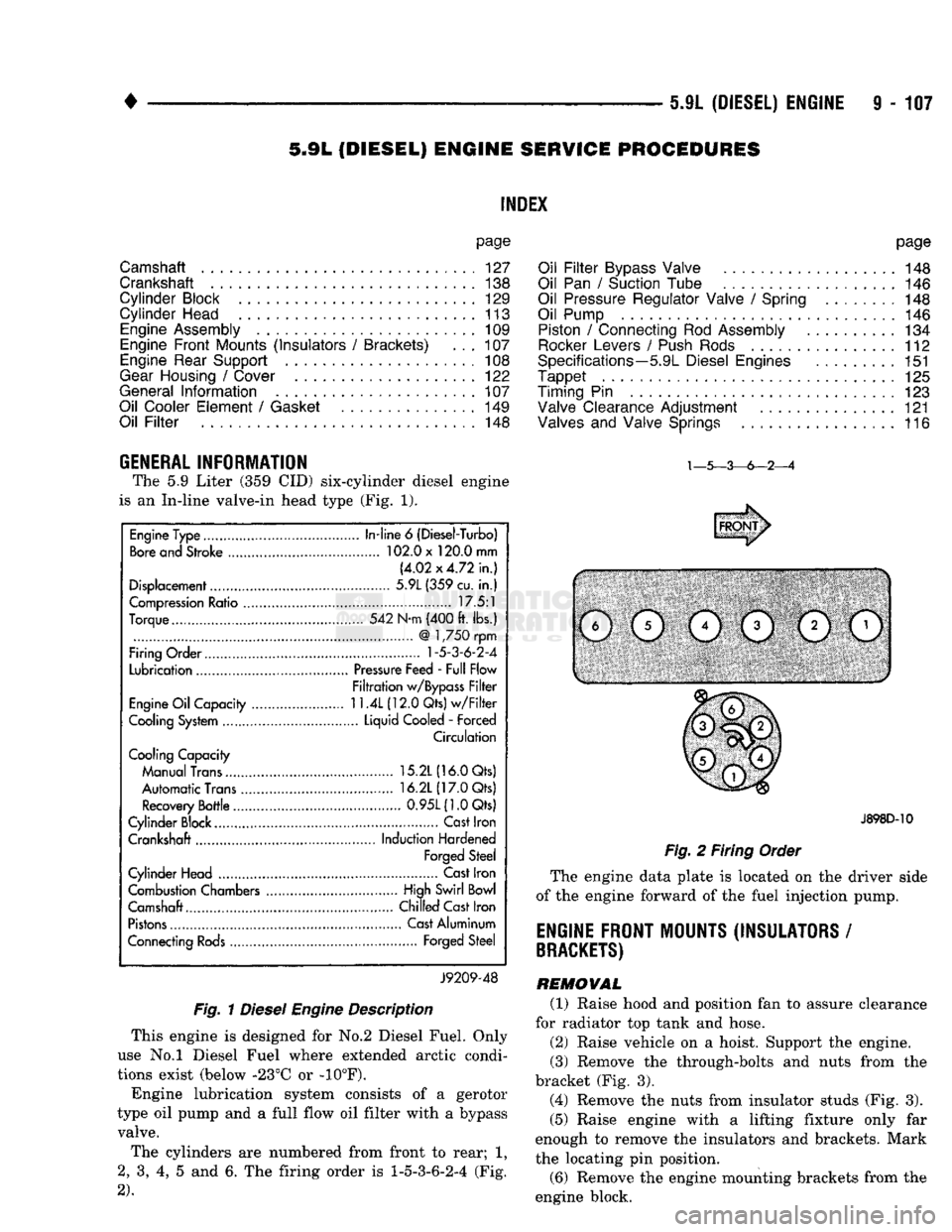
GENERAL INFORMATION The
5.9
Liter
(359 CID)
six-cylinder diesel engine
is
an
In-line valve-in head type
(Fig. 1).
Fig.
1
Diesel
Engine
Description
This engine
is
designed
for No.2
Diesel Fuel. Only
use
No.l
Diesel Fuel where extended arctic condi
tions exist (below -23°C
or -10°F).
Engine lubrication system consists
of a
gerotor
type
oil
pump
and a
full flow
oil
filter with
a
bypass valve.
The cylinders
are
numbered from front
to
rear;
1,
2,
3, 4, 5 and 6. The
firing order
is
1-5-3-6-2-4
(Fig.
2).
J898D-10
Fig.
2
Firing Order
The engine data plate
is
located
on the
driver side
of
the
engine forward
of the
fuel injection pump.
ENGINE FRONT MOUNTS (INSULATORS
/
BRACKETS)
REMOVAL (1) Raise hood
and
position
fan to
assure clearance
for radiator
top
tank
and
hose.
(2) Raise vehicle
on a
hoist. Support
the
engine.
(3) Remove
the
through-bolts
and
nuts from
the
bracket
(Fig. 3).
(4) Remove
the
nuts from insulator studs
(Fig. 3).
(5) Raise engine with
a
lifting fixture only
far
enough
to
remove
the
insulators
and
brackets. Mark
the locating
pin
position.
(6) Remove
the
engine mounting brackets from
the
engine block.
Engine Type
In-line
6
(Diesel-Turbo)
Bore and Stroke 102.0 x 120.0 mm
(4.02x4.72 in.)
Displacement 5.9L (359 cu.
in.)
Compression Ratio 17.5:1
Torque 542 N-m (400 ft. lbs.)
@
1,750 rpm
Firing Order
1-5-3-6-2-4
Lubrication Pressure Feed - Full Flow
Filtration w/Bypass Filter
Engine Oil Capacity
11.4L
(12.0 Qts) w/Filter
Cooling System Liquid Cooled
-
Forced
Circulation
Cooling Capacity
Manual Trans 15.2L (16.0 Qts)
Automatic Trans 16.2L (17.0 Qts)
Recovery Bottle 0.95L(1.0Qts)
Cylinder Block.... Cast Iron
Crankshaft Induction Hardened
Forged Steel
Cylinder Head Cast Iron
Combustion Chambers High Swirl Bowl
Camshaft.... Chilled Cast Iron
Pistons Cast Aluminum
Connecting Rods Forged Steel
J9209-48
Page 714 of 1502
•
5.9L
(DIESEL) ENGINE
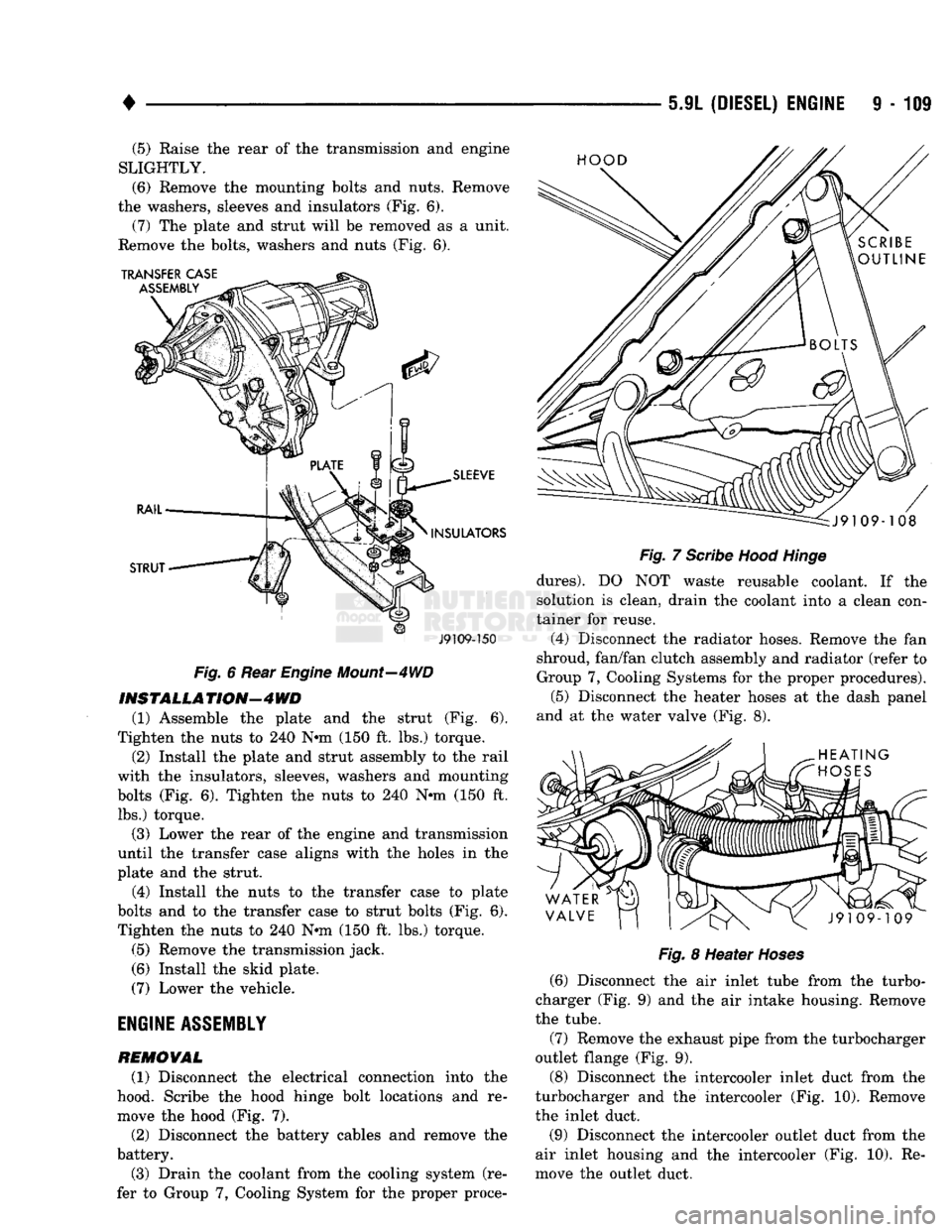
9 - 109 (5) Raise the rear of the transmission and engine
SLIGHTLY.
(6)
Remove the mounting bolts and nuts. Remove
the washers, sleeves and insulators (Fig. 6). (7) The plate and strut will be removed as a unit.
Remove the bolts, washers and nuts (Fig. 6).
J9109-150
Fig.
6 Rear
Engine
Mount—4WD
INSTALL A
TION—4
WD
(1) Assemble the plate and the strut (Fig. 6).
Tighten the nuts to 240 N-m (150 ft. lbs.) torque.
(2) Install the plate and strut assembly to the rail
with the insulators, sleeves, washers and mounting
bolts (Fig. 6). Tighten the nuts to 240 N-m (150 ft. lbs.) torque.
(3) Lower the rear of the engine and transmission
until the transfer case aligns with the holes in the
plate and the strut.
(4) Install the nuts to the transfer case to plate
bolts and to the transfer case to strut bolts (Fig. 6). Tighten the nuts to 240 N-m (150 ft. lbs.) torque.
(5) Remove the transmission jack.
(6) Install the skid plate.
(7) Lower the vehicle.
ENGINE
ASSEMBLY
REMOVAL
(1) Disconnect the electrical connection into the
hood. Scribe the hood hinge bolt locations and re
move the hood (Fig. 7).
(2) Disconnect the battery cables and remove the
battery.
(3) Drain the coolant from the cooling system (re
fer to Group 7, Cooling System for the proper proce-
Fig.
7
Scribe
Hood
Hinge
dures).
DO NOT waste reusable coolant. If the
solution is clean, drain the coolant into a clean con
tainer for reuse.
(4) Disconnect the radiator hoses. Remove the fan
shroud, fan/fan clutch assembly and radiator (refer to
Group 7, Cooling Systems for the proper procedures). (5) Disconnect the heater hoses at the dash panel
and at the water valve (Fig. 8).
Fig.
8 Heater
Hoses
(6) Disconnect the air inlet tube from the turbo
charger (Fig. 9) and the air intake housing. Remove
the tube.
(7) Remove the exhaust pipe from the turbocharger
outlet flange (Fig. 9).
(8) Disconnect the intercooler inlet duct from the
turbocharger and the intercooler (Fig. 10). Remove
the inlet duct.
(9) Disconnect the intercooler outlet duct from the
air inlet housing and the intercooler (Fig. 10). Re
move the outlet duct.
Page 717 of 1502
9
- 112 5.9L
(DIESEL)
ENGINE
• (5) Position the engine in the chassis and install
the through bolt. Tighten the through bolt nut to 41
N-m (30 ft. lbs.) torque. (6) Make sure the lifting brackets are mounted
with the eye down. (7) Remove the covers or tape covering the engine
openings. (8) Connect the fuel lines to the lift pump and fuel
return.
(9) Connect all electrical connections.
(10) Connect the power steering lines.
(11) Raise and support the vehicle on a hoist.
(12) AUTOMATIC TRANSMISSION:
CAUTION:
If new
flex
plate is installed, remove
flashing
from the engine
back
plate at the 5 and 7
o'clock
positions.
(a) Rotate converter until alignment mark on the
converter is aligned with mark on drive plate.
Off
set holes in plate are next to 1/8 inch hole in inner
circle of drive plate.
(b) Install bell housing bolts. Tighten the bolts to
41 N-m (30 ft. lbs.) torque. (c) With the torque converter plate aligned to the
torque converter, install and tighten the bolts to 31 N-m (270 in. lbs.) torque. (d) Install the converter housing access plate.
(e) Remove the transmission support.
(13) MANUAL TRANSMISSION:
Refer to Group 21, Transmissions for the G360
Manual Transmission Installation procedure. (14) Connect the ground cable and tighten the nut
to 22 N-m (16 ft. lbs.) torque. Connect the solenoid cable and tighten the nut to 5 N-m (44 in. lbs.)
torque.
(15) Connect the transmission cooler lines.
(16) Install the exhaust pipe to the exhaust sys
tem.
(17) Lower the vehicle.
(18) Install the A/C compressor and tighten the
bolts to 47 N-m (35 ft. lbs.) torque. If removed, con nect the clutch electrical wire.
(19) Install the generator. Tighten the upper
mounting bolts to 24 N-m (18 ft. lbs.) torque. Now
tighten the lower mounting bolts to 43 N-m (32 ft. lbs.) torque. Connect all wires.
(20) Install the radiator, fan/fan clutch assembly
and fan shroud (refer to Group 7, Cooling Systems
for the proper procedures). Connect the radiator
hoses.
(21) Position the intercooler inlet duct to the tur
bocharger and the intercooler. With the clamps in po sition, tighten the clamp nut to 8 N-m (72 in. lbs.)
torque. (22) Position the intercooler outlet duct to the air
inlet housing and the intercooler. With the clamps in
position, tighten the clamp nut to 8 N-m (72 in. lbs.)
torque.
(23) Connect the air intake tube to the turbo
charger inlet flange and the air cleaner housing.
Tighten the clamps to 8 N-m (72 in. lbs.) torque. (24) Install the exhaust pipe to the turbocharger.
Tighten the steady rest clamp to 8 N-m (72 in. lbs.) torque.
(25) Make sure the air intake and exhaust pipe
connections are tight and free of leaks.
(26) Fill the engine with the required amount of
clean engine lubricating oil (refer to Group 0, Lubri cation and Maintenance).
(27) Fill the cooling system with a mixture of 50%
water and 50% ethylene-glycol base antifreeze (refer Group 7, Cooling System for the proper procedure).
(28) Install the battery and connect the battery ca
bles.
(29) Check the oil level after the engine has run
for 2 or 3 minutes. Oil held in the oil filter and oil passages will cause the oil level in the pan to be lower.
(30) Operate the engine at idle for 5 to 10 minutes
and check for leaks and loose parts.
ROCKER LEVERS
/
POSH
RODS
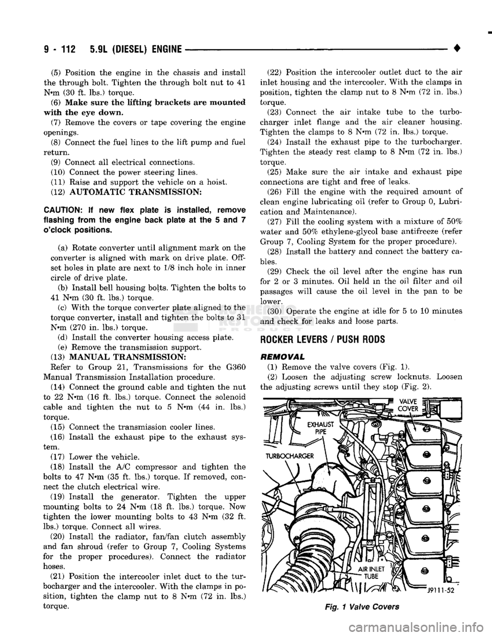
REMOVAL (1) Remove the valve covers (Fig. 1). (2) Loosen the adjusting screw locknuts. Loosen
the adjusting screws until they stop (Fig. 2).
Page 719 of 1502
9
- 114 5.9L
(DIESEL) ENGINE
—
Fig.
4
Exhaust
Manifold
(6) Remove the fuel lines and injector nozzles (re
fer to Group 14, Fuel System).
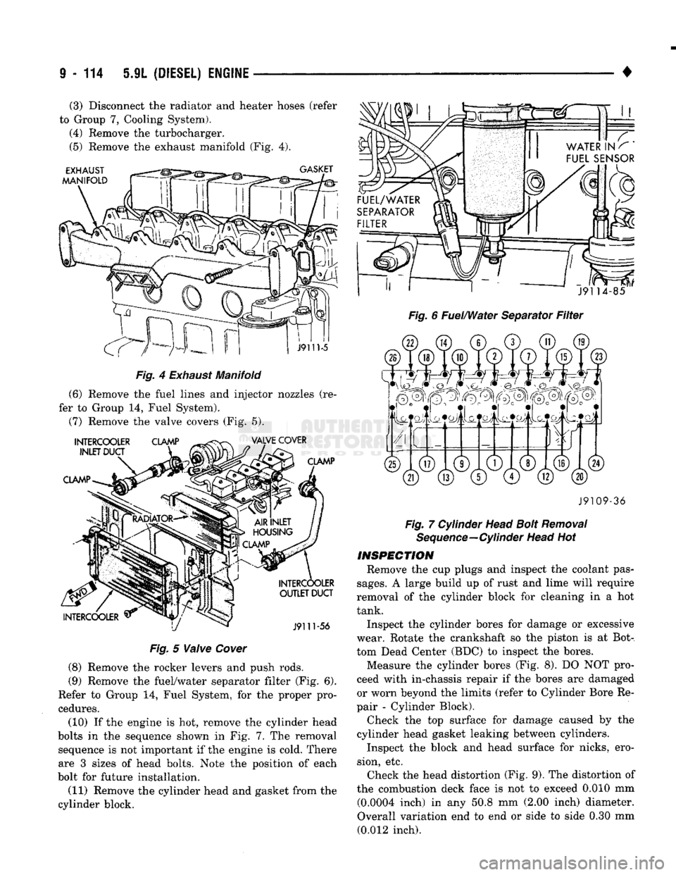
(7) Remove the valve covers (Fig. 5).
Fig.
5
Valve
Cover
(8) Remove the rocker levers and push rods.
(9) Remove the fuel/water separator filter (Fig. 6).
Refer to Group 14, Fuel System, for the proper pro
cedures.
(10) If the engine is hot, remove the cylinder head
bolts in the sequence shown in Fig. 7..The removal sequence is not important if the engine is cold. There
are 3 sizes of head bolts. Note the position of each
bolt for future installation.
(11) Remove the cylinder head and gasket from the
cylinder block.
•
Fig. 6 Fuel/Water Separator Filter J9109-36
Fig. 7 Cylinder Head Bolt Removal Sequence—Cylinder Head Hot
INSPECTION
Remove the cup plugs and inspect the coolant pas
sages.
A large build up of rust and lime will require
removal of the cylinder block for cleaning in a hot
tank.
Inspect the cylinder bores for damage or excessive
wear. Rotate the crankshaft so the piston is at Bot
tom Dead Center (BDC) to inspect the bores. Measure the cylinder bores (Fig. 8). DO NOT pro
ceed with in-chassis repair if the bores are damaged
or worn beyond the limits (refer to Cylinder Bore Re
pair - Cylinder Block).
Check the top surface for damage caused by the
cylinder head gasket leaking between cylinders.
Inspect the block and head surface for nicks, ero
sion, etc. Check the head distortion (Fig. 9). The distortion of
the combustion deck face is not to exceed 0.010 mm (0.0004 inch) in any 50.8 mm (2.00 inch) diameter.
Overall variation end to end or side to side 0.30 mm (0.012 inch).
(3) Disconnect the radiator and heater hoses (refer
to Group 7, Cooling System). (4) Remove the turbocharger.
(5) Remove the exhaust manifold (Fig. 4).
Page 721 of 1502
9
- 116 5.9L
(DIESEL) ENGINE
•
CYLINDER HEAD
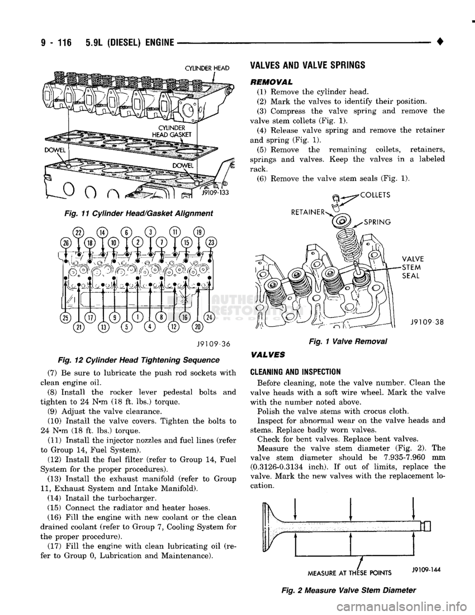
Fig. 11 Cylinder Head/Gasket Alignment J9109-36
Fig. 12 Cylinder Head Tightening Sequence
(7) Be sure to lubricate the push rod sockets with
clean engine oil.
(8) Install the rocker lever pedestal bolts and
tighten to 24 N*m (18 ft. lbs.) torque. (9) Adjust the valve clearance.
(10) Install the valve covers. Tighten the bolts to
24 N*m (18 ft. lbs.) torque.
(11) Install the injector nozzles and fuel lines (refer
to Group 14, Fuel System).
(12) Install the fuel filter (refer to Group 14, Fuel
System for the proper procedures). (13) Install the exhaust manifold (refer to Group
11,
Exhaust System and Intake Manifold).
(14) Install the turbocharger.
(15) Connect the radiator and heater hoses. (16) Fill the engine with new coolant or the clean
drained coolant (refer to Group 7, Cooling System for
the proper procedure). (17) Fill the engine with clean lubricating oil (re
fer to Group 0, Lubrication and Maintenance).
VALVES
AND VALVE
SPRINGS
REMOWAL
(1) Remove the cylinder head.
(2) Mark the valves to identify their position.
(3) Compress the valve spring and remove the
valve stem collets (Fig. 1). (4) Release valve spring and remove the retainer
and spring (Fig. 1).
(5) Remove the remaining collets, retainers,
springs and valves. Keep the valves in a labeled
rack.
(6) Remove the valve stem seals (Fig. 1). -38
Fig. 1 Valve Removal
WALVES
CLEANING AND INSPECTION
Before cleaning, note the valve number. Clean the
valve heads with a soft wire wheel. Mark the valve
with the numbet* noted above.
Polish the valve stems with crocus cloth.
Inspect for abnormal wear on the valve heads and
stems.
Replace badly worn valves. Check for bent valves. Replace bent valves.
Measure the valve stem diameter (Fig. 2). The
valve stem diameter should be 7.935-7.960 mm (0.3126-0.3134 inch). If out of limits, replace the
valve. Mark the new valves with the replacement lo cation. Ik 1
MEASURE
AT THESE POINTS
Fig. 2 Measure Valve Stem Diameter