1993 DODGE TRUCK radiator
[x] Cancel search: radiatorPage 617 of 1502
9
- 12
ENGINES
•
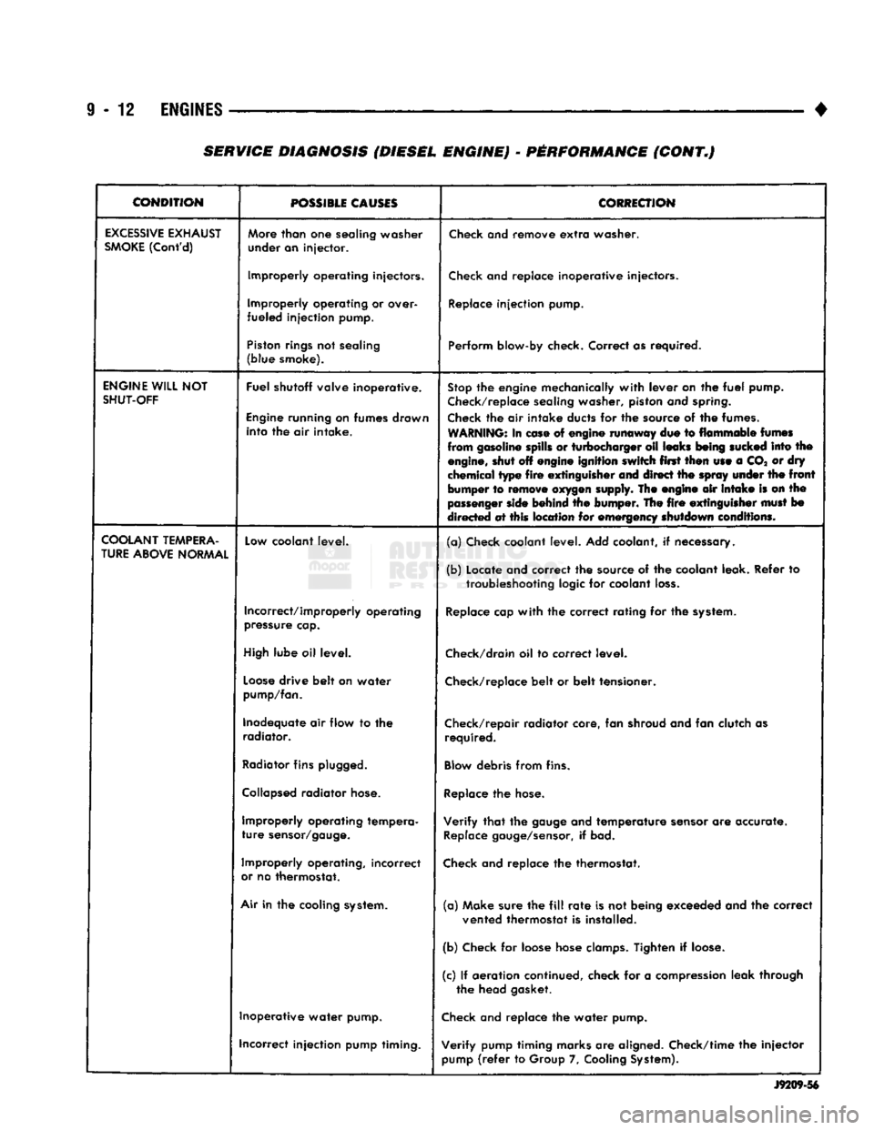
CONDITION
POSSIBLE
CAUSES
CORRECTION
EXCESSIVE
EXHAUST
SMOKE
(Cont'd)
More
than
one
sealing washer
under an injector.
Check
and remove
extra
washer.
Improperly operating injectors.
Check
and replace inoperative injectors.
Improperly operating or over-
fueled injection pump.
Replace
injection pump.
Piston
rings
not sealing
(blue smoke). Perform blow-by check. Correct as required.
ENGINE
WILL
NOT
SHUT-OFF
Fuel shutoff valve inoperative.
Engine
running on fumes drawn into the air intake.
Stop
the engine mechanically
with
lever on the
fuel
pump.
Check/replace
sealing washer, piston and
spring.
Check
the air intake ducts for the source of the fumes.
WARNING:
In
ease
of engine runaway due to flammable
fumes
from gasoline spills or turbocharger oil leaks
being
sucked
into the
engine,
shut off engine ignition switch first then use a CO* or dry
chemical type
fire
extinguisher
and direct the
spray
under
the
front
bumper to
remove
oxygen
supply. The engine air
intake
is on the
passenger
side
behind the bumper. The
fire
extinguisher
must
bo
directed at this location for emergency shutdown conditions.
COOLANT
TEMPERA
TURE
ABOVE
NORMAL
Low
coolant level.
(a) Check coolant level. Add coolant, if necessary.
(b) Locate and correct the source of the coolant leak. Refer to
troubleshooting
logic for coolant
loss.
Incorrect/improperly operating
pressure
cap.
Replace
cap
with
the correct rating for the
system.
High
lube oil level.
Check/drain
oil to correct level.
Loose
drive belt on water
pump/fan.
Check/replace
belt or belt tensioner.
Inadequate air flow to the radiator. Check/repair radiator core, fan shroud and fan clutch as
required.
Radiator
fins
plugged.
Blow
debris from fins.
Collapsed
radiator
hose.
Replace
the
hose.
Improperly operating tempera
ture
sensor/gauge.
Verify
that
the
gauge
and temperature
sensor
are accurate.
Replace
gauge/sensor,
if bad.
Improperly operating, incorrect
or
no thermostat.
Check
and replace the thermostat.
Air
in the cooling
system.
(a) Make sure the
fill
rate
is not being exceeded and the correct
vented thermostat is installed.
(b) Check for loose hose
clamps.
Tighten if
loose.
(c) If aeration continued, check for a
compression
leak through the head gasket.
Inoperative water pump.
Check
and replace the water pump.
incorrect injection pump timing. Verify pump timing marks are aligned. Check/time the injector
pump
(refer
to Group 7,
Cooling
System).
J9209-56
SERVICE DIAGNOSIS (DIESEL ENGINE) - PERFORMANCE (CONT.)
Page 618 of 1502
•
ENGINES
9 - 13
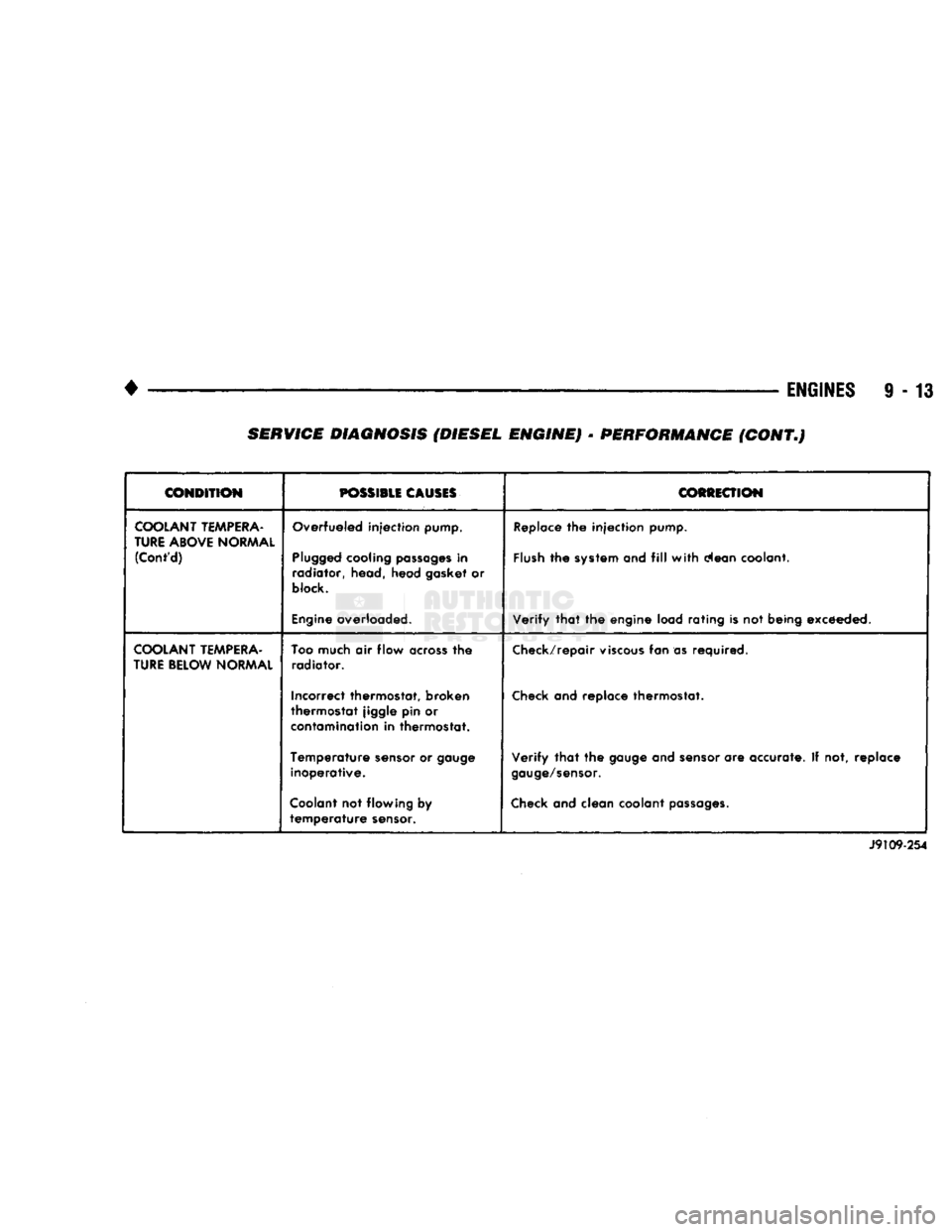
CONDITION
POSSIBLE
CAUSES
COfiiiECTION
COOLANT
TEMPERA
TURE
ABOVE
NORMAL
(Cont'd)
Overfueled injection pump.
Plugged
cooling
passages
in
radiator, head, head gasket or
block.
Engine
overloaded.
Replace
the injection
pump.
Flush
the
system
and
fill
with
clean coolant.
Verify
that
the engine load rating is not being exceeded.
COOLANT
TEMPERA
TURE
BELOW
NORMAL
Too
much air flow
across
the
radiator.
Incorrect thermostat, broken
thermostat jiggle pin or
contamination
in thermostat.
Temperature
sensor
or
gauge
inoperative.
Coolant
not flowing by
temperature
sensor.
Check/repair
viscous
fan as required.
Check
and replace thermostat.
Verify
that
the
gauge
and
sensor
are accurate. If not, replace
gauge/sensor.
Check
and clean coolant
passages.
J9109-254
SERVICE DIAGNOSIS (DIESEL ENGINE) • PERFORMANCE (CONT.)
Page 623 of 1502
9
- 18 3.9L
ENGINE
• (2) Raise hood and position fan to assure clearance
for radiator top tank and hose.
CAUTION:
DO NOT
lift
the engine by the
intake
manifold.
(3) Install engine lifting fixture.
(4) Raise vehicle on hoist.
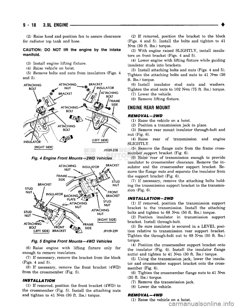
(5) Remove bolts and nuts from insulators (Figs. 4
and 5).
ATTACHING
BOLT
ATTACHING
NUT
BRACKET
INSULATOR
ATTACHING
BOLT
FRAME
SIDE
INSULATOR?
(RIGHT
SIDE)
(LEFT
SIDE)
J9109-238
Fig.
4
Engine
Front
Mounts—2WD
Vehicles
ATTACHING
NUT
FRAME
SIDE
INSULATOR
BRACKET
STUD
NUT»
STUD NUT
ATTACHING
BOLT INSULATOR
BACKING.
PLATE
ATTACHING
NUT
BRACKET
STUD NUT
FRONT
BRACKET
STUD NUT
ATTACHING
NUT
FRAME
s,de
(RIGHT
SIDE)
J9109-239
Fig.
5
Engine
Front
Mounts—4WD
Vehicles
(6) Raise engine with lifting fixture only far
enough to remove insulators.
(7) If necessary, remove the bracket from the block
(Figs.
4 and 5).
(8) If necessary, remove the front bracket (4WD)
from the crossmember (Fig. 5).
INSTALLATION (1) If removed, position the front bracket (4WD) to
the crossmember (Fig. 5). Install the attaching nuts and tighten to 41 N»m (30 ft. lbs.) torque. (2) If removed, position the bracket to the block
(Figs.
4 and 5). Install the bolts and tighten to 41
N*m (30 ft. lbs.) torque. (3) With engine raised SLIGHTLY, install insula
tors on front bracket (Figs. 4 and 5).
(4) Lower engine with lifting fixture while guiding
insulator studs into brackets.
(5) Install attaching bolts and nuts (Figs. 4 and 5).
Tighten the attaching bolts and nuts to 41 N«m (30 ft. lbs.) torque,
(6) Install insulator stud nuts and washers.
Tighten the stud nuts to 102 N»m (75 ft. lbs.) torque.
(7) Lower the vehicle.
(8) Remove lifting fixture.
ENGINE
REAR
MOUNT
REMOVAL-2WD (1) Raise the vehicle on a hoist. (2) Position a transmission jack in place.
(3) Remove rear mount insulator through-bolt and
nut (Fig. 6). (4) Raise rear of transmission and engine
SLIGHTLY.
(5) Remove the flange nuts from the frame cross-
member support bracket (Fig. 6). (6) Raise rear of transmission enough to provide
insulator to crossmember clearance. Remove the in sulator and the crossmember support bracket. Re
move the flange nuts and separate the insulator from
the support bracket (Fig. 6).
(7) If necessary, remove the attaching bolts hold
ing the transmission support bracket to the transmis
sion (Fig. 6).
INSTALLA
TION-2WD
(1) If removed, position the transmission support
bracket to the transmission. Install the attaching
bolts and tighten to 68 N*m (50 ft. lbs.) torque.
(2) Position insulator in transmission support
bracket. Install through-bolt.
(3) Be sure insulator is secured in a LEVEL posi
tion relative to transmission rear support bracket.
Tighten the through-bolt nut to 68 N*m (50 ft. lbs.) torque.
(4) Position the crossmember support bracket onto
the insulator (Fig. 6). Install the insulator flange nut(s) and tighten to 41 Nnn (30 ft. lbs.) torque.
(5) Using the transmission jack, lower the insula
tor and crossmember support bracket onto the cross- member (Fig. 6).
(6) Tighten the crossmember flange nuts to 41 Nnn
(30 ft. lbs.) torque.
(7) Remove the transmission jack.
(8) Lower the vehicle.
HE MO
VAL—4
WD (1) Raise the vehicle on a hoist.
Page 625 of 1502
TRANSFER
CASE
INSULATOR
MOUNTING PLATE
NUT(B
RAIL
ASSEMBLY
SPACER
UPPER
INSULATOR
NUT®
LOWER
INSULATOR
J9109-242
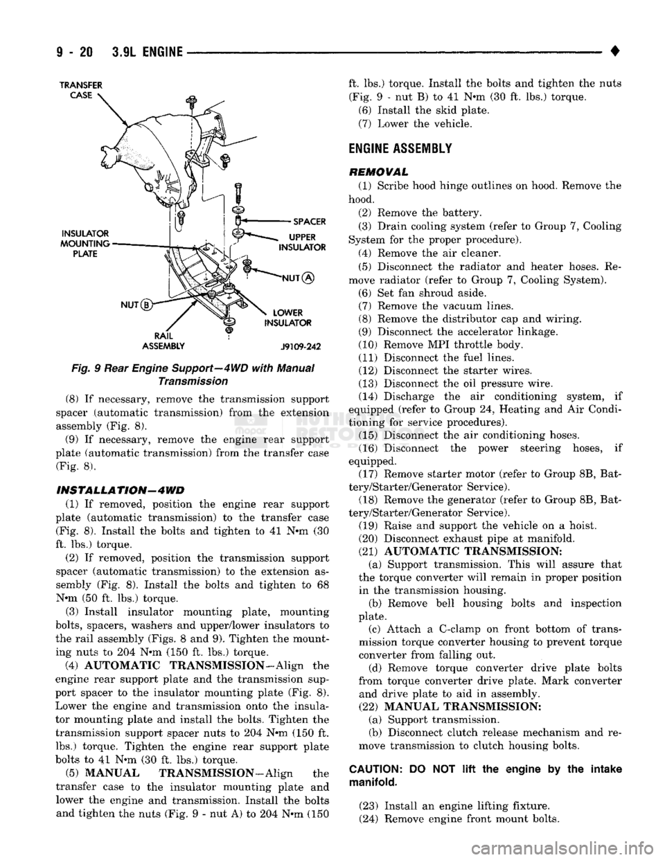
Fig.
9 Rear
Engine
Support—4WD
with
Manual
Transmission
(8) If necessary, remove the transmission support
spacer (automatic transmission) from the extension
assembly (Fig. 8).
(9) If necessary, remove the engine rear support
plate (automatic transmission) from the transfer case (Fig. 8).
INSTALLATION-4WD
(1) If removed, position the engine rear support
plate (automatic transmission) to the transfer case (Fig. 8). Install the bolts and tighten to 41 N-m (30
ft. lbs.) torque.
(2) If removed, position the transmission support
spacer (automatic transmission) to the extension as
sembly (Fig. 8). Install the bolts and tighten to 68 N-m (50 ft. lbs.) torque.
(3) Install insulator mounting plate, mounting
bolts,
spacers, washers and upper/lower insulators to
the rail assembly (Figs. 8 and 9). Tighten the mount
ing nuts to 204 N*m (150 ft. lbs.) torque.
(4) AUTOMATIC TRANSMISSION-Align the
engine rear support plate and the transmission sup
port spacer to the insulator mounting plate (Fig. 8). Lower the engine and transmission onto the insula
tor mounting plate and install the bolts. Tighten the transmission support spacer nuts to 204 N-m (150 ft. lbs.) torque. Tighten the engine rear support plate
bolts to 41 N-m (30 ft. lbs.) torque.
(5) MANUAL TRANSMISSION—Align the
transfer case to the insulator mounting plate and lower the engine and transmission. Install the bolts and tighten the nuts (Fig. 9 - nut A) to 204 N-m (150 ft. lbs.) torque. Install the bolts and tighten the nuts
(Fig. 9 - nut B) to 41 N-m (30 ft. lbs.) torque. (6) Install the skid plate.
(7) Lower the vehicle.
ENGINE
ASSEMBLY
REMOVAL (1) Scribe hood hinge outlines on hood. Remove the
hood.
(2) Remove the battery. (3) Drain cooling system (refer to Group 7, Cooling
System for the proper procedure).
(4) Remove the air cleaner. (5) Disconnect the radiator and heater hoses. Re
move radiator (refer to Group 7, Cooling System).
(6) Set fan shroud aside. (7) Remove the vacuum lines. (8) Remove the distributor cap and wiring.
(9) Disconnect the accelerator linkage.
(10) Remove MPI throttle body. (11) Disconnect the fuel lines. (12) Disconnect the starter wires.
(13) Disconnect the oil pressure wire. (14) Discharge the air conditioning system, if
equipped (refer to Group 24, Heating and Air Condi
tioning for service procedures). (15) Disconnect the air conditioning hoses.
(16) Disconnect the power steering hoses, if
equipped. (17) Remove starter motor (refer to Group 8B, Bat
tery/Starter/Generator Service). (18) Remove the generator (refer to Group 8B, Bat
tery/Starter/Generator Service).
(19) Raise and support the vehicle on a hoist.
(20) Disconnect exhaust pipe at manifold.
(21) AUTOMATIC TRANSMISSION: (a) Support transmission. This will assure that
the torque converter will remain in proper position in the transmission housing. (b) Remove bell housing bolts and inspection
plate.
(c) Attach a C-clamp on front bottom of trans
mission torque converter housing to prevent torque
converter from falling out.
(d) Remove torque converter drive plate bolts
from torque converter drive plate. Mark converter and drive plate to aid in assembly.
(22) MANUAL TRANSMISSION: (a) Support transmission.
(b) Disconnect clutch release mechanism and re
move transmission to clutch housing bolts.
CAUTION:
DO NOT
lift
the engine by the intake
manifold.
(23) Install an engine lifting fixture.
(24) Remove engine front mount bolts.
Page 626 of 1502
•
3.9L
ENGINE
9 - 21 (25) Lower the vehicle.
(26) On automatic transmission vehicles, discon
nect the engine from the torque converter drive
plate. On manual transmission vehicles, move engine forward until drive pinion shaft clears the clutch
disc.
Remove engine from engine compartment. (27) Install engine assembly on engine repair
stand.
INSTALLATION (1) Remove engine from the repair stand and posi
tion in the engine compartment.
(2) Install engine support fixture.
(3) Raise and support the vehicle on a hoist.
(4)
AUTOMATIC TRANSMISSION: (a) Position the torque converter and drive plate.
Install torque converter drive plate bolts. Tighten
the bolts to 31 Nnn (270 in. lbs.) torque.
(b) Install the engine front mounts.
(c) Install bell housing bolts. Tighten the bolts to
41 N-m (30 ft. lbs.) torque.
(d) Remove C-clamp.
(e) Install the inspection plate.
(5) MANUAL TRANSMISSION: (a) Position the drive pinion shaft to the clutch
disc.
(b) Connect the clutch release mechanism and
install the transmission to clutch bolts. Tighten the
bolts to 68 N-m (50 ft. lbs.) torque.
(c) Install the engine front mounts.
(6) Remove transmission support.
(7) Install exhaust pipe to manifold.
(8) Lower the vehicle.
(9) Remove engine lifting fixture.
(10) Install the generator (refer to Group 8B, Bat
tery/Starter/Generator Service). (11) Install starter motor (refer to Group 8B, Bat
tery/Starter/Generator Service). (12) Connect power steering hoses, if equipped.
(13) Connect air conditioning hoses.
(14) Evacuate and charge the air conditioning sys
tem, if equipped (refer to Group 24, Heater and Air Conditioning for service procedures). (15) Using a new gasket, install MPI throttle body.
Tighten the throttle body bolts to 23 N-m (200 in. lbs.) torque. (16) Connect the accelerator linkage.
(17) Connect the starter wires. (18) Connect the oil pressure wire.
(19) Install the distributor cap and wiring.
(20) Connect the vacuum lines.
(21) Connect the fuel lines.
(22) Install the radiator (refer to Group 7, Cooling
System). Connect the radiator hoses and heater
hoses.
(23) Install fan shroud in position. (24) Fill cooling system (refer to Group 7, Cooling
System for the proper procedures). (25) Install the air cleaner.
(26) Install the battery.
(27) Warm engine and adjust.
(28) Install hood and line up with the scribe
marks. (29) Road test vehicle.
CYLINDER
HEAD COVER
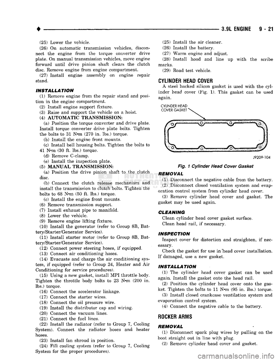
A steel backed silicon gasket is used with the cyl
inder head cover (Fig. 1). This gasket can be used again.
CYLINDER HEAD COVER GASKET
J9209-104
Fig.
1 Cylinder Head
Cover
Gasket
REMOVAL (1) Disconnect the negative cable from the battery.
(2) Disconnect closed ventilation system and evap
oration control system from cylinder head cover. (3) Remove cylinder head cover and gasket. The
gasket may be used again.
CLEANING Clean cylinder head cover gasket surface. Clean head rail, if necessary.
INSPECTION Inspect cover for distortion and straighten, if nec
essary. Check the gasket for use in "head cover installation.
If damaged, use a new gasket.
INSTALLATION (1) The cylinder head cover gasket can be used
again. Install the gasket onto the head rail.
(2) Position the cylinder head cover onto the gas
ket. Tighten the bolts to 11 N-m (95 in. lbs.) torque. (3) Install closed crankcase ventilation system and
evaporation control system.
(4) Connect the negative cable to the battery.
ROCKER
ARMS
REMOVAL (1) Disconnect spark plug wires by pulling on the
boot straight out in line with plug.
(2) Remove cylinder head cover and gasket.
Page 652 of 1502
5.2L
ENGINE
9 - 47
S.2L ENGINE
SERVICE
PROCEDURES
INDEX
page
Camshaft
. , . 61
Crankshaft
68
Crankshaft Main Bearings
69
Crankshaft Rear
Oil
Seals
...... ........
70
Cylinder Block ...........................
71
Cylinder Head Cover
. . . . 51
Cylinder Heads
52
Distributor
62
Engine
Assembly
. 50
Engine
Front Mounts
47
Engine
Rear Mount ...............
48
Front Crankshaft
Oil
Seal Replacement
. . 61
GENERAL
INFORMATION
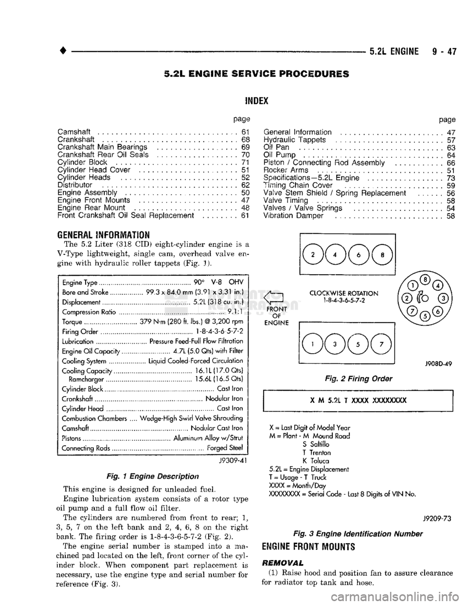
The 5.2 Liter (318 CID) eight-cylinder engine is a
V-Type lightweight, single cam, overhead valve en gine with hydraulic roller tappets (Fig. J).
Engine
Type ....
90° V-8 OHV
Bore
and Stroke .....
99.3
x
84.0 mm
(3.91
x
3.31
in.)
Displacement................
5.2L(318cu.
in.)
Compression
Ratio ....... .
9.1:1
Torque .. 379 N-m (280
ft.
lbs.)
@
3,200
rpm
Firing Order .... 1-8-4-3-6-5-7-2
Lubrication
.......
Pressure
Feed-Full Flow
Filtration
Engine
Oil
Capacity......
4.7L
(5.0 Qts)
with Filter
Cooling System ...... Liquid Cooled-Forced
Circulation
Cooling Capacity..........
16.1L(17.0Qts)
Ramcharger
15.6L
(16.5 Qts)
Cylinder Block
,
Cast
Iron
Crankshaft Nodular Iron
Cylinder Head ..............
Cast
Iron
Combustion Chambers
..
Wedge-High
Swirl Valve Shrouding
Camshaft Nodular Cast Iron
Pistons
Aluminum Alloy
w/Strut
Connecting
Rods...........
Forged
Steel
J9309-41
Fig. 1
Engine
Description
This engine is designed for unleaded fuel.
Engine lubrication system consists of a rotor type
oil pump and a full flow oil filter.
The cylinders are numbered from front to rear; 1?
3,
5, 7 on the left bank and 2, 4, 6, 8 on the right
bank. The firing order is 1-8-4-3-6-5-7-2 (Fig. 2).
The engine serial number is stamped into a ma
chined pad located on the left, front corner of the cyl
inder block. When component part replacement is
necessary, use the engine type and serial number for
reference (Fig. 3).
page
General
Information
.......................
47
Hydraulic Tappets
57
Oil
Pan . 63
Oil Pump
. 64
Piston
/
Connecting
Rod
Assembly
66
Rocker
Arms
51
Specifications—5.2L Engine
73
Timing Chain Cover ................
59
Valve Stem Shield
/
Spring Replacement
56
Valve Timing
. 58
Valves
/
Valve Springs
54
Vibration
Damper
. . 58
J908D-49
Fig.
2 Firing Order
X
M 5.2L T
XXXX
XXXXXXXX
X
~
Last Digit of
Model
Year
M
=
Plant
- M
Mound
Road
S
Saltillo
T
Trenton
K
Toluca
5.2L
=
Engine Displacement
T
=
Usage
-
T Truck
XXXX
=
Month/Day
XXXXXXXX
=
Serial Code
-
Last
8
Digits
of
VIN
No.
J9209-73
Fig.
3
Engine
Identification
Number
ENGINE
FRONT
MOUNTS
REMOVAL
(1) Raise hood and position fan to assure clearance
for radiator top tank and hose.
Page 655 of 1502
TRANSFER
CASE
TRANSFER
CASE
ENGINE
REAR
SUPPORT PLATE
EXTENSION
ASSEMBLY
TRANSMISSION
SUPPORT
SPACER
SPACER
UPPER
INSULATOR
INSULATOR
MOUNTING
PLATE
LOWER
INSULATOR
fT^RAIL
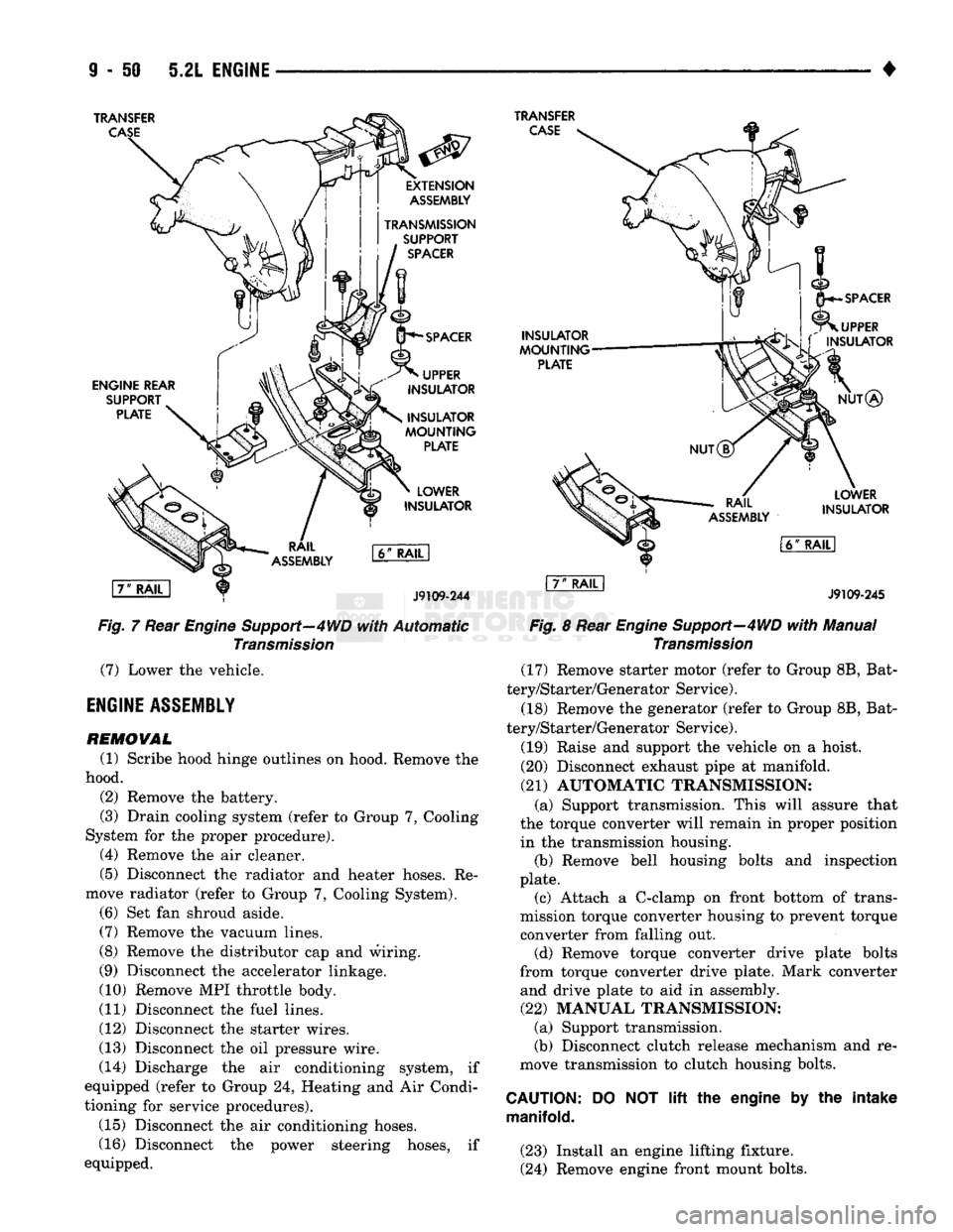
J9109-244
Fig,
7 Rear Engine Support—4WD
with
Automatic
Transmission
(7)
Lower the vehicle.
ENGINE
ASSEMBLY
REMOVAL
(1) Scribe hood hinge outlines on hood. Remove the
hood. (2) Remove the battery.
(3) Drain cooling system (refer to Group 7, Cooling
System for the proper procedure). (4) Remove the air cleaner.
(5) Disconnect the radiator and heater hoses. Re
move radiator (refer to Group 7, Cooling System). (6) Set fan shroud aside.
(7)
Remove the vacuum lines.
(8) Remove the distributor cap and wiring.
(9) Disconnect the accelerator linkage.
(10) Remove MPI throttle body.
(11) Disconnect the fuel lines.
(12) Disconnect the starter wires.
(13) Disconnect the oil pressure wire.
(14) Discharge the air conditioning system, if
equipped (refer to Group 24, Heating and Air Condi
tioning for service procedures).
(15) Disconnect the air conditioning hoses.
(16) Disconnect the power steering hoses, if
equipped.
INSULATOR
MOUNTING
PLATE
SPACER
UPPER
L\ f
INSULATOR
NUT®
RAIL
ASSEMBLY
LOWER
INSULATOR
l6ff
RAIL
I
J9109-245
Fig.
8 Rear
Engine
Support—4WD
with
Manual
Transmission
(17) Remove starter motor (refer to Group 8B, Bat
tery/Starter/Generator Service).
(18) Remove the generator (refer to Group 8B, Bat
tery/Starter/Generator Service).
(19) Raise and support the vehicle on a hoist.
(20) Disconnect exhaust pipe at manifold.
(21)
AUTOMATIC TRANSMISSION: (a) Support transmission. This will assure that
the torque converter will remain in proper position in the transmission housing. (b) Remove bell housing bolts and inspection
plate. (c) Attach a C-clamp on front bottom of trans
mission torque converter housing to prevent torque
converter from falling out. (d) Remove torque converter drive plate bolts
from torque converter drive plate. Mark converter and drive plate to aid in assembly.
(22)
MANUAL TRANSMISSION; (a) Support transmission.
(b) Disconnect clutch release mechanism and re
move transmission to clutch housing bolts.
CAUTION:
manifold.
DO
NOT lift the
engine
by the
intake
(23) Install an engine lifting fixture.
(24) Remove engine front mount bolts.
Page 656 of 1502
•
5.2L
ENGINE
9 - 51 (25) Lower the vehicle.
(26) On automatic transmission vehicles, discon
nect the engine from the torque converter drive
plate. On manual transmission vehicles, move engine forward until drive pinion shaft clears the clutch
disc.
Remove engine from engine compartment.
(27) Install engine assembly on engine repair
stand.
INSTALLATION
(1) Remove engine from the repair stand and posi
tion in the engine compartment.
(2) Install an engine support fixture.
(3) Raise and support the vehicle on a hoist.
(4) AUTOMATIC TRANSMISSION: (a) Position the torque converter and drive plate.
Install torque converter drive plate bolts. Tighten
the bolts to 31 N-m (270 in. lbs.) torque.
(b) Install the engine front mounts.
(c) Install bell housing bolts. Tighten the bolts to
41 N-m (30 ft. lbs.) torque.
(d) Remove C-clamp.
(e) Install the inspection plate.
(5) MANUAL TRANSMISSION: (a) Position the drive pinion shaft to the clutch
disc.
(b) Connect the clutch release mechanism and
install the transmission to clutch bolts. Tighten the
bolts to 68 N-m (50 ft. lbs.) torque.
(c) Install the engine front mounts.
(6) Remove transmission support.
(7) Install exhaust pipe to manifold. (8) Lower the vehicle.
(9) Remove engine lifting fixture. (10) Install the generator (refer to Group 8B, Bat
tery/Starter/ Generator Service). (11) Install the starter motor (refer to Group 8B,
Battery/Starter/Generator Service). (12) Connect power steering hoses, if so equipped.
(13) Connect air conditioning hoses.
(14) Evacuate and charge the air conditioning sys
tem, if equipped (refer to Group 24, Heater and Air Conditioning for service procedures).
(15) Using a new gasket, install MPI throttle body.
Tighten the throttle body bolts to 23 N-m (200 in. lbs.) torque. (16) Connect the accelerator linkage.
(17) Connect the starter wires.
(18) Connect the oil pressure wire. (19) Install the distributor cap and wiring.
(20) Connect the vacuum lines.
(21) Connect the fuel lines,
(22) Install the radiator (refer to Group 7, Cooling
System). Connect the radiator hoses and heater
hoses.
(23) Install fan shroud in position.
(24) Fill cooling system (refer to Group 7, Cooling
System for the proper procedure). (25) Install the air cleaner.
(26) Install the battery. (27) Warm engine and adjust.
(28) Install hood and line up with the scribe
marks. (29) Road test vehicle.
CYLIiiER
HEAD
COVER
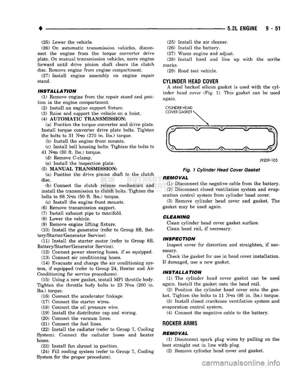
A steel backed silicon gasket is used with the cyl
inder head cover (Fig. 1). This gasket can be used
again.
CYLINDER HEAD
J9209-105
Fig.
1 Cylinder Head
Cover
Gasket
REMOVAL
(1) Disconnect the negative cable from the battery.
(2) Disconnect closed ventilation system and evap
oration control system from cylinder head cover.
(3) Remove cylinder head cover and gasket. The
gasket may be used again.
CLEANING
Clean cylinder head cover gasket surface. Clean head rail, if necessary.
INSPECTION
Inspect cover for distortion and straighten, if nec
essary.
Check the gasket for use in head cover installation.
If damaged, use a new gasket.
INSTALLATION
(1) The cylinder head cover gasket can be used
again. Install the gasket onto the head rail.
(2) Position the cylinder head cover onto the gas
ket. Tighten the bolts to 11 N-m (95 in. lbs.) torque.
(3) Install closed crankcase ventilation system and
evaporation control system.
(4) Connect the negative cable to the battery.
ROCKER ARMS
REMOVAL
(1) Disconnect spark plug wires by pulling on the
boot straight out in line with plug. (2) Remove cylinder head cover and gasket.