1993 DODGE TRUCK relay
[x] Cancel search: relayPage 848 of 1502
•
FUEL
SYSTEM
14-29
MULTI-PORT
FUEL
INJECTION
(MPI)-COMPONENT DESCRIPTION/SYSTEM
OPERATION-EXCEPT DIESEL
INDEX
page
Air
Conditioning (A/C) Clutch
Relay-Pern
Output
. 35
Air
Conditioning (A/C)
Controls—PCM
Input
.... 31
Auto
Shut
Down
(ASD)
Relay-PCM
Output
. ... 36
Automatic
Shut
Down
(ASD)
Sense-PCM
Input
. 31
Battery
Voltage-PCM
Input
32
Brake
Switch-PCM
Input
32
Camshaft
Position
Sensor—PCM
Input
32
Charge
Air
Temperature
Sensor—PCM
Input
. . . 32
Crankshaft
Position
Sensor-PCM
Input
.......
32
Electric
Exhaust
Gas Recirculation Transducer
(EET)
Solenoid-PCM
Output
...
.......
36
Engine
Coolant Temperature
Sensor—PCM
Input
. 33
EVAP
Canister
Purge
Solenoid—PCM
Output
. . . 37
Fuel
Injectors-PCM Output
37
Fuel
Pressure
Regulator
41
Fuel
Rail
41
General
Information
.......................
29
Generator
Field-PCM
Output
36
Generator
Lamp-PCM
Output
36
Idle
Air
Control
(IAC)
Motor-PCM
Output
......
36
Ignition
Circuit
Sense—PCM
Input
33
GENERAL
INFORMATION
All
gas
powered engines
are
equipped with sequen
tial Multi-Port Fuel Injection (MPI).
The MPI
system (Fig.
1)
provides precise air/fuel ratios
for all
driving
conditions. The Powertrain Control Module
(PCM)
operates
the fuel system.
The PCM was
formerly referred
to
as
the
SBEC
or
engine controller.
The PCM is a
pre
programmed, dual microprocessor digital computer. It regulates ignition timing, air-fuel ratio, emission
control devices, charging system, speed control,
air
conditioning compressor clutch engagement
and
idle speed.
The PCM can
adapt
its
programming
to
meet
changing operating conditions.
Powertrain Control Module (PCM) Inputs rep
resent
the
instantaneous engine operating conditions.
Air-fuel mixture
and
ignition timing calibrations
for
various driving
and
atmospheric conditions
are
pre
programmed into
the PCM. The PCM
monitors
and
analyzes various inputs.
It
then computes engine fuel
and ignition timing requirements based
on
these
in
puts.
Fuel delivery control
and
ignition timing will
then
be
adjusted accordingly. Other inputs
to the
PCM
are
provided
by the
brake
light switch,
air
conditioning select switch
and the
speed control switches.
All
inputs
to the PCM are
converted into signals. Electrically operated fuel injectors spray fuel
in
precise metered amounts into
the
intake port directly above
the
intake valve.
The
injectors
are
fired
in a
specific sequence
by the PCM. The PCM
maintains
page
Ignition
Coil-PCM
Output
37
Malfunction Indicator
Lamp—PCM
Output
37
Manifold
Absolute
Pressure
(MAP)
Sensor-
PCM
Input
33
Open
Loop/Closed
Loop
Modes
of
Operation
. . . 38
Overdrive/Override
Switch
34
Oxygen
(02)
Sensor—PCM
Input
33
Park/Neutral
Switch—PCM
Input
34
Power
Ground
34
Powertrain Control Module
(PCM)
30
SCI
Receive-PCM
Input
. 34
SCI
Transmit-PCM
Output
37
Sensor
Return
—PCM
Input
35
Shift Indicator-PCM Output
38
Speed
Control-PCM
Input
34
Speed
Control-PCM
Output
38
SRI
Lamp-PCM
Output
36
Tachometer—PCM
Output
38
Throttle
Body
40
Throttle
Position
Sensor
(TPS)-PCM
Input
35
Vehicle
Speed
Sensor-PCM
Input
35
an air/fuel ratio
of 14.7 to 1 by
constantly adjusting
injector pulse width. Injector pulse width
is the
length
of
time that
the
injector opens
and
sprays fuel into
the
chamber.
The PCM
adjusts injector pulse
width
by
opening
and
closing
the
ground path
to the
injector.
Manifold absolute pressure
(air
density)
and
engine
rpm (speed)
are the
primary inputs that determine
fuel injector pulse width.
The PCM
also monitors
other inputs when adjusting air-fuel ratio.
Inputs That Effect Fuel Injector Pulse Width:
• Exhaust
gas
oxygen content
• Coolant temperature
• Manifold absolute pressure (MAP)
• Engine speed
• Throttle position
• Battery voltage •
Air
conditioning selection
• Transmission gear selection (auto, trans.)
• Speed control The powertrain control module (PCM) adjusts igni
tion timing
by
controlling ignition coil operation.
The
ignition coil receives battery voltage when
the
igni
tion
key is in the run or
starter (crank) position.
The
PCM provides
a
ground
for the
ignition coil.
The
coil
discharges when
the PCM
supplies
a
ground.
By
switching
the
ground path
on and off, the PCM
reg
ulates ignition timing.
The sensors
and
switches that provide inputs
to the
powertrain control module
(PCM)
comprise
the En-
Page 849 of 1502
14
- 30
FUEL
SYSTEM
INPUTS
OUTPUTS
POWERTRAIN
CONTROL
MODULE
DRB
II
SCAN
TOOL
SPEED
CONTROL
BRAKE
SWITCH
A/C
LOW
PRESSURE
CUTOFF
SWITCH VEHICLE
SPEED
SENSOR PARK/NEUTRAL
SWITCH TORQUE CONVERTER
CLUTCH SOLENOID
MALFUNCTION
INDICATOR
LAMP
m
HEATED
i
*OXYGEN SENSOR ENGINE
COOLANT
yy
BATTERY
TEMPERATURE
SENSOR
MAP SENSOR
i—r
CHARGE
AIR
TEMPERATURE
SENSOR
AIR CHARGE
TEMPERATURE
SENSOR
DISTRIBUTOR
WITH
CAMSHAFT
r
POSITION
SENSOR
(|
TACHOMETER
A/C
CLUTCH RELAY
AUTO
SHUTDOWN
RELAY OVERDRIVE
SOLENOID
IDLE AIR
CONTROL MOTOR
SPEED
CONTROL
SHIFT
INDICATOR
LAMP
EMISSION
CONTROL SOLENOIDS
IGNITION
COIL
OVERDRIVE
OVERRIDE SWITCH
ASD
SENSE
FUEL
INJECTORS
PARK
THROTTLE
SOLENOID
GENERATOR CRANKSHAFT
POSITION FUEL
PUMP
RELAY
J9314-117
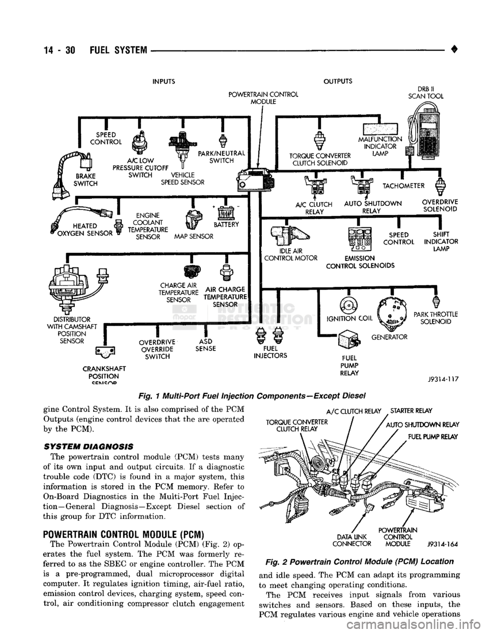
Fig.
1 Multi-Port
Fuel
Injection
Components—Except
Diesel
gine Control System. It is also comprised of the PCM Outputs (engine control devices that the are operated
by the PCM).
SYSTEM DIAGNOSIS
The powertrain control module (PCM) tests many
of its own input and output circuits. If a diagnostic
trouble code (DTC) is found in a major system, this information is stored in the PCM memory. Refer to
On-Board Diagnostics in the Multi-Port Fuel Injec
tion—General Diagnosis—Except Diesel section of
this group for DTC information.
POWERTRAIN
CONTROL MODULE (PCM)
The Powertrain Control Module (PCM) (Fig. 2) op
erates the fuel system. The PCM was formerly re
ferred to as the SBEC or engine controller. The PCM is a pre-programmed, dual microprocessor digital computer. It regulates ignition timing, air-fuel ratio, emission control devices, charging system, speed control, air conditioning compressor clutch engagement
A/C
CLUTCH RELAY STARTER RELAY
TORQUE CONVERTER CLUTCH RELAY
AUTO
SHUTDOWN RELAY
FUEL PUMP RELAY
DATA UNK
CONNECTOR
POWERTRAIN
CONTROL MODULE
J9314-164
Fig.
2 Powertrain Control
Module
(PCM) Location and idle speed. The PCM can adapt its programming
to meet changing operating conditions.
The PCM receives input signals from various
switches and sensors. Based on these inputs, the
PCM regulates various engine and vehicle operations
Page 850 of 1502
•
FUEL SYSTEM
14-31 through different system components. These compo
nents are referred to as Powertrain Control Module
(PCM) Outputs. The sensors and switches that pro
vide inputs to the PCM are considered Powertrain Control Module (PCM) Inputs.
The PCM adjusts ignition timing based upon in
puts it receives from sensors that react to: engine rpm, manifold absolute pressure, engine coolant tem
perature, throttle position, transmission gear selec
tion (automatic transmission), vehicle speed and the
brake switch.
The PCM adjusts idle speed based on inputs it re
ceives from sensors that react to: throttle position,
vehicle speed, transmission gear selection, engine coolant temperature and from inputs it receives from
the air conditioning clutch switch and brake switch.
Based on inputs that it receives, the PCM adjusts
ignition coil dwell. The PCM also adjusts the gener
ator charge rate through control of the generator
field and provides speed control operation.
Powertrain Control Module (PCM) Inputs:
• Generator output • A/C request (if equipped with factory A/C)
• A/C select (if equipped with factory A/C)
• Auto shut down (ASD) sense
• Charge air temperature sensor
• Battery voltage
• Brake switch
• Engine coolant temperature sensor
• Crankshaft position sensor • Ignition circuit sense (ignition switch in run posi
tion)
• Manifold absolute pressure (MAP) sensor
• Overdrive/override switch
• Oxygen sensor(s)
• Park/neutral switch (auto, trans, only)
• SCI receive (DRB II connection) • Speed control resume switch
• Speed control set switch • Speed control on/off switch
• Camshaft position sensor signal
• Throttle position sensor
• Vehicle speed sensor
• Sensor return
• Power ground
• Signal ground Powertrain Control Module (PCM) Outputs:
• A/C clutch relay
• Idle air control (IAC) motor
• Auto shut down (ASD) relay
• Generator field
• Malfunction indicator lamp
• Service reminder indicator lamp
• EGR valve control solenoid • Fuel injectors
• Fuel pump relay
• Ignition coil • EVAP canister purge solenoid
• SCI transmit (DRB II connection)
• Shift indicator lamp (manual transmission only)
• Speed control vacuum solenoid
• Speed control vent solenoid
• Tachometer (on instrument panel, if equipped) The powertrain control module (PCM) contains a
voltage convertor. This converts battery voltage to a
regulated 8.0 volts. It is used to power the crankshaft
position sensor and camshaft position sensor. The
PCM also provides a five (5) volt supply for the man ifold absolute pressure (MAP) sensor and throttle po
sition sensor (TPS).
AIR
CONDITIONING
(A/C)
CONTROLS-PCM
INPUT
The A/C control system information applies to fac
tory installed air conditioning units. A/C SELECT SIGNAL: When the A/C switch is
in the ON position and the A/C low pressure switch
is closed, an input signal is sent to the powertrain
control module (PCM). The signal informs the PCM
that the A/C has been selected. The PCM adjusts idle speed to a pre-programmed rpm through the idle air
control (IAC) motor to compensate for increased en
gine load. A/C REQUEST SIGNAL: Once A/C has been se
lected, the powertrain control module (PCM) receives
the A/C request signal from the evaporator switch.
The input indicates that the evaporator temperature is in the proper range for A/C application. The PCM
uses this input to cycle the A/C compressor clutch (through the A/C relay). It will also determine the
correct engine idle speed through the idle air control (IAC) motor position. If the A/C low pressure switch opens (indicating a
low refrigerant level), the PCM will not receive an
A/C select signal. The PCM will then remove the ground from the A/C relay. This will deactivate the
A/C compressor clutch. If the evaporator switch opens, (indicating that
evaporator is not in proper temperature range), the
PCM will not receive the A/C request signal. The
PCM will then remove the ground from the A/C re lay, deactivating the A/C compressor clutch.
AUTOMATIC SHUT DOWN
(ASD)
SENSE-PCM INPUT
A 12 volt signal at this input indicates to the PCM
that the ASD has been activated. The ASD relay is located in the engine compartment (Fig. 2). It is used
to connect the oxygen sensor(s) heater element, igni
tion coil, generator field winding and fuel injectors to 12 volt + power supply. This input is used only to sense that the ASD relay
is energized. If the powertrain control module (PCM)
does not see 12 volts at this input when the ASD
should be activated, it will set a diagnostic trouble
code (DTC).
Page 854 of 1502
•
FUEL SYSTEM
14 - 35
SENSOR
RETURN—PCM
INPUT
Sensor Return provides a low noise ground refer
ence for all system sensors.
THROTTLE POSITION
SENSOR
(TPS)-PCM
INPUT
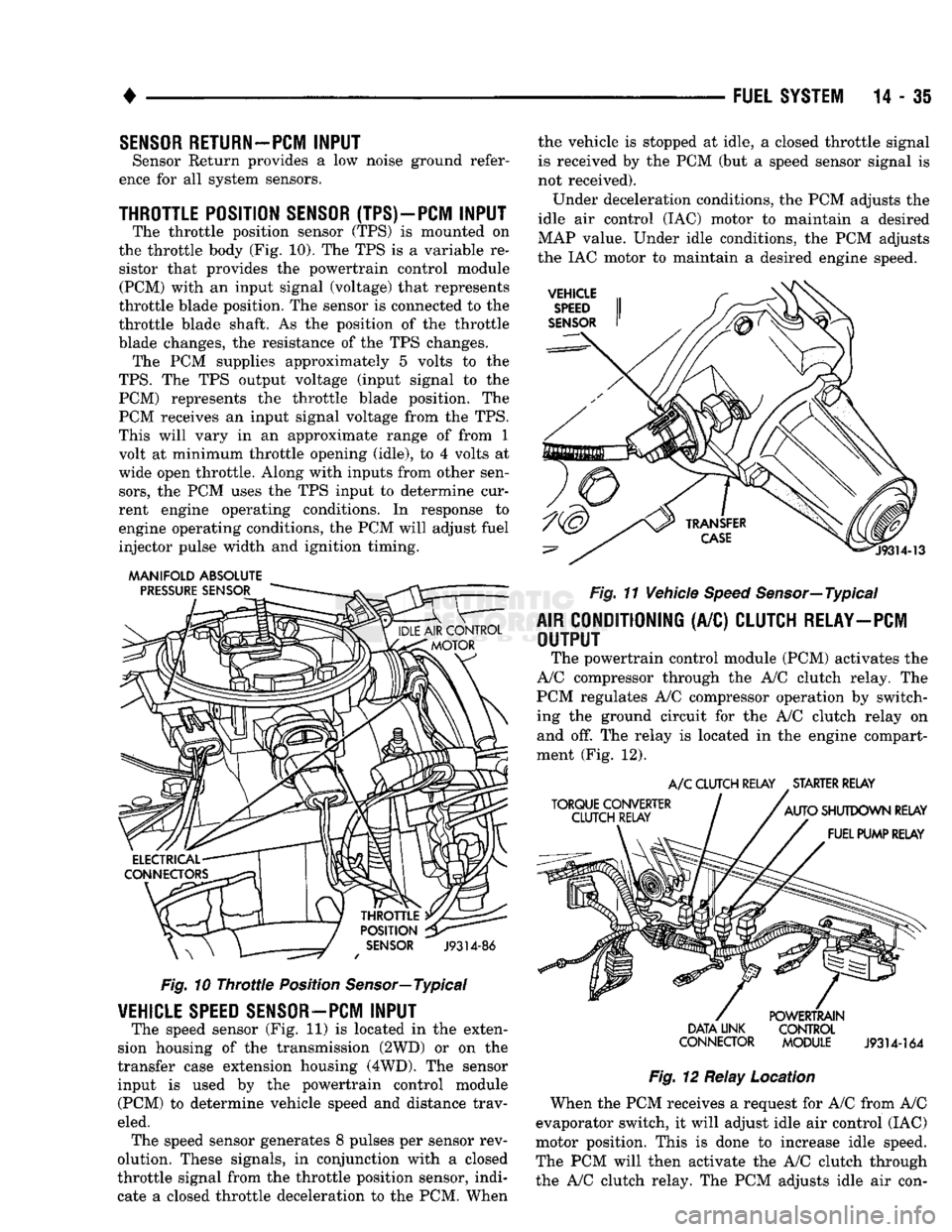
The throttle position sensor (TPS) is mounted on
the throttle body (Fig. 10). The TPS is a variable re sistor that provides the powertrain control module (PCM) with an input signal (voltage) that represents
throttle blade position. The sensor is connected to the
throttle blade shaft. As the position of the throttle
blade changes, the resistance of the TPS changes. The PCM supplies approximately 5 volts to the
TPS.
The TPS output voltage (input signal to the PCM) represents the throttle blade position. The
PCM receives an input signal voltage from the TPS.
This will vary in an approximate range of from 1
volt at minimum throttle opening (idle), to 4 volts at
wide open throttle. Along with inputs from other sen
sors,
the PCM uses the TPS input to determine cur
rent engine operating conditions. In response to
engine operating conditions, the PCM will adjust fuel
injector pulse width and ignition timing.
MANIFOLD ABSOLUTE
Fig.
10
Throttle
Position Sensor—Typical
VEHICLE
SPEED
SENSOR—PCM
INPUT
The speed sensor (Fig. 11) is located in the exten
sion housing of the transmission (2WD) or on the
transfer case extension housing (4WD). The sensor input is used by the powertrain control module (PCM) to determine vehicle speed and distance trav
eled. The speed sensor generates 8 pulses per sensor rev
olution. These signals, in conjunction with a closed
throttle signal from the throttle position sensor, indi
cate a closed throttle deceleration to the PCM. When the vehicle is stopped at idle, a closed throttle signal
is received by the PCM (but a speed sensor signal is
not received).
Under deceleration conditions, the PCM adjusts the
idle air control (IAC) motor to maintain a desired
MAP value. Under idle conditions, the PCM adjusts
the IAC motor to maintain a desired engine speed.
Fig.
11 Vehicle
Speed
Sensor—Typical
AIR
CONDITIONING
(A/C)
CLUTCH RELAY—PCM
OUTPUT
The powertrain control module (PCM) activates the
A/C compressor through the A/C clutch relay. The
PCM regulates A/C compressor operation by switch
ing the ground circuit for the A/C clutch relay on and off. The relay is located in the engine compart
ment (Fig. 12).
A/C
CLUTCH RELAY STARTER RELAY
DATA LINK CONTROL
CONNECTOR MODULE
J9314-164
Fig.
12 Relay Location
When the PCM receives a request for A/C from A/C
evaporator switch, it will adjust idle air control (IAC)
motor position. This is done to increase idle speed.
The PCM will then activate the A/C clutch through
the A/C clutch relay. The PCM adjusts idle air con-
Page 855 of 1502
trol (IAC) stepper motor position to compensate for
increased engine load from the A/C compressor.
By switching the ground path for the relay on and
off, the PCM is able to cycle the A/C compressor
clutch. This is based on changes in engine operating
conditions. If, during A/C operation, the PCM senses
low idle speeds or a wide open throttle condition, it
will de-energize the relay. This prevents A/C clutch engagement. The relay will remain de-energized un
til the idle speed increases or the wide open throttle condition exceeds 15 seconds or no longer exists. The
PCM will also de-energize the relay if coolant tem
perature exceeds 125°C (257°F).
IDLE
AIR
CONTROL
(IAC)
MOTOR-PCM OUTPUT
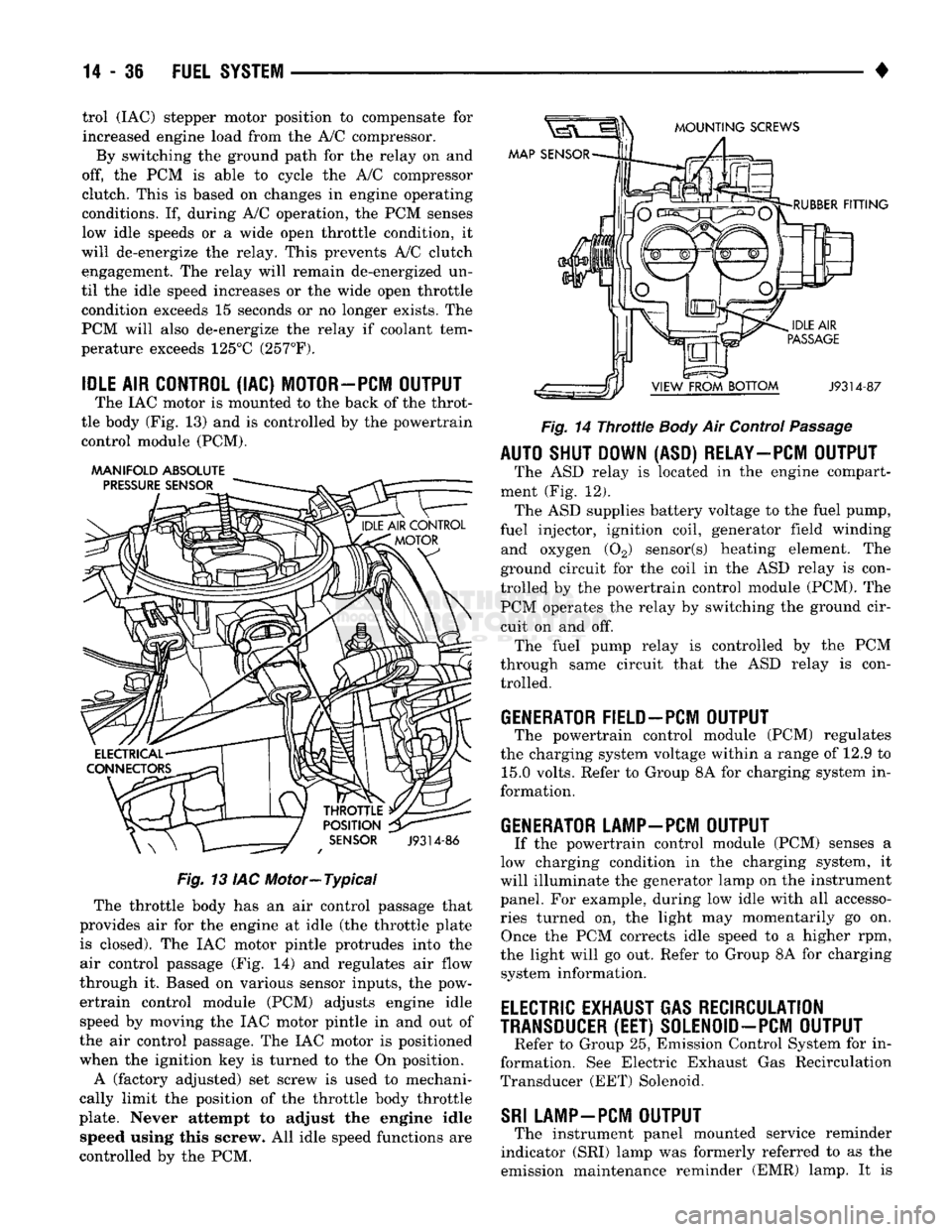
The IAC motor is mounted to the back of the throt
tle body (Fig. 13) and is controlled by the powertrain control module (PCM).
AAANIFOLD ABSOLUTE
PRESSURE
SENSOR
MOUNTING
SCREWS
MAP SENSOR
THROTTLE
POSITION
SENSOR
J9314-86
Fig.
13 IAC Motor—Typical The throttle body has an air control passage that
provides air for the engine at idle (the throttle plate is closed). The IAC motor pintle protrudes into the
air control passage (Fig. 14) and regulates air flow
through it. Based on various sensor inputs, the pow
ertrain control module (PCM) adjusts engine idle speed by moving the IAC motor pintle in and out of
the air control passage. The IAC motor is positioned
when the ignition key is turned to the On position.
A (factory adjusted) set screw is used to mechani
cally limit the position of the throttle body throttle
plate. Never attempt to adjust the engine idle speed using this screw. All idle speed functions are
controlled by the PCM.
RUBBER
FITTING
J9314-87
Fig.
14
Throttle
Body
Air Control
Passage
AUTO SHUT DOWN (ASD) RELAY—PCM OUTPUT
The ASD relay is located in the engine compart
ment (Fig. 12). The ASD supplies battery voltage to the fuel pump,
fuel injector, ignition coil, generator field winding and oxygen (02) sensor(s) heating element. The
ground circuit for the coil in the ASD relay is con
trolled by the powertrain control module (PCM). The PCM operates the relay by switching the ground cir
cuit on and off. The fuel pump relay is controlled by the PCM
through same circuit that the ASD relay is con trolled.
GENERATOR FIELD-PCM OUTPUT
The powertrain control module (PCM) regulates
the charging system voltage within a range of 12.9 to 15.0 volts. Refer to Group 8A for charging system in
formation.
GENERATOR LAMP-PCM OUTPUT
If the powertrain control module (PCM) senses a
low charging condition in the charging system, it
will illuminate the generator lamp on the instrument
panel. For example, during low idle with all accesso
ries turned on, the light may momentarily go on. Once the PCM corrects idle speed to a higher rpm,
the light will go out. Refer to Group 8A for charging system information.
ELECTRIC
EXHAUST GAS RECIRCULATION
TRANSDUCER
(EET)
S0LEN0ID-PCM OUTPUT
Refer to Group 25, Emission Control System for in
formation. See Electric Exhaust Gas Recirculation
Transducer (EET) Solenoid.
SRI
LAMP-PCM OUTPUT
The instrument panel mounted service reminder
indicator (SRI) lamp was formerly referred to as the
emission maintenance reminder (EMR) lamp. It is
Page 856 of 1502
•
FUEL SYSTEM
14 - 37 used only on vehicles equipped with the 5.9L heavy
duty cycle (HDC) engine. Refer to Group 25, Emis
sion Control System for information.
EVAP CANISTER PURGE SOLENOID-PCM
OUTPUT
Refer to Group 25, Emission Control System. See
EVAP Canister Purge Solenoid.
FUEL INJECTORS-PCM
OUTPUT
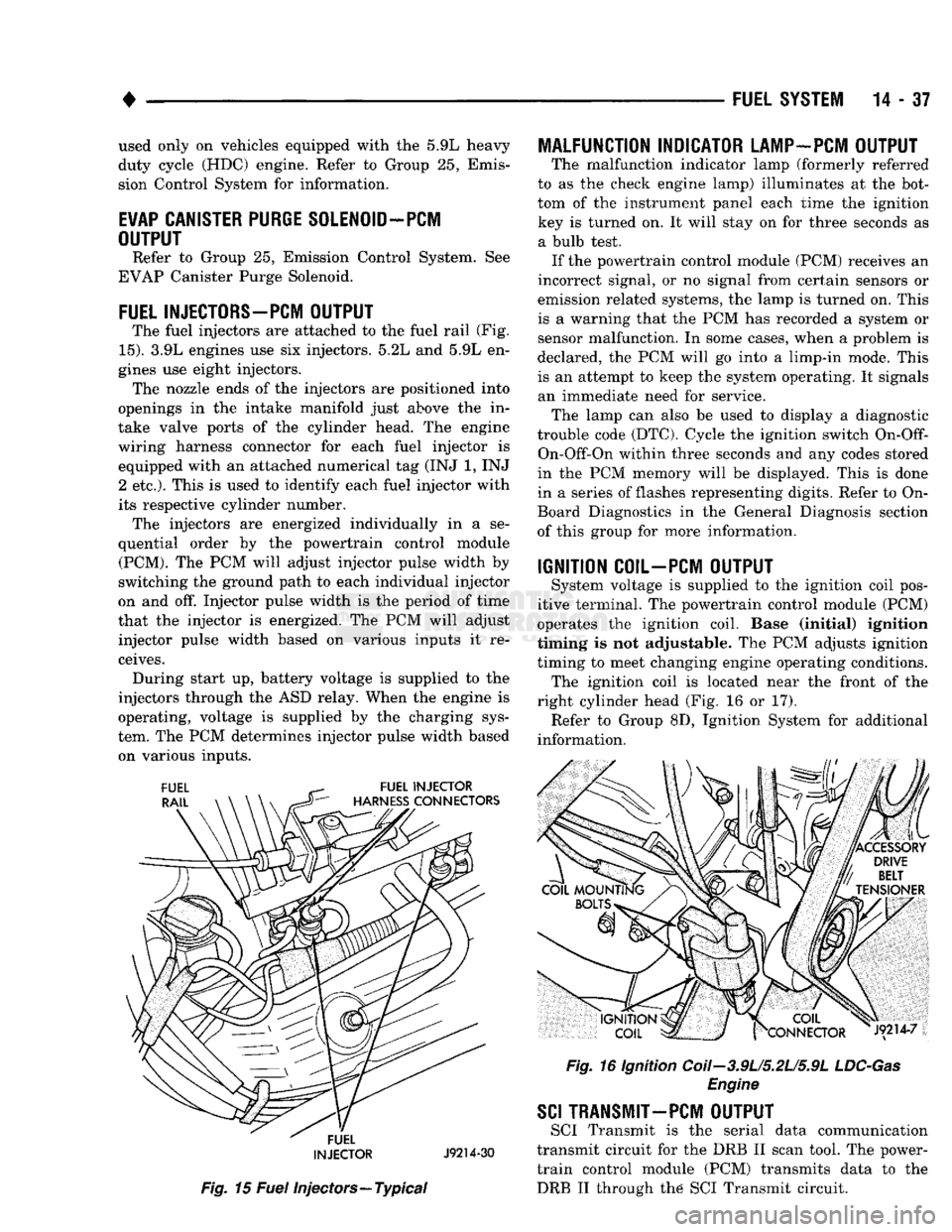
The fuel injectors are attached to the fuel rail (Fig.
15).
3.9L engines use six injectors. 5.2L and 5.9L en
gines use eight injectors. The nozzle ends of the injectors are positioned into
openings in the intake manifold just above the in
take valve ports of the cylinder head. The engine
wiring harness connector for each fuel injector is equipped with an attached numerical tag (INJ 1, INJ 2 etc.). This is used to identify each fuel injector with
its respective cylinder number. The injectors are energized individually in a se
quential order by the powertrain control module (PCM). The PCM will adjust injector pulse width by
switching the ground path to each individual injector
on and off. Injector pulse width is the period of time
that the injector is energized. The PCM will adjust injector pulse width based on various inputs it re
ceives. During start up, battery voltage is supplied to the
injectors through the ASD relay. When the engine is
operating, voltage is supplied by the charging sys
tem. The PCM determines injector pulse width based on various inputs.
FUEL
INJECTOR
J9214-30
Fig.
15
Fuel
injectors—Typical
MALFUNCTION INDICATOR LAMP-PCM OUTPUT
The malfunction indicator lamp (formerly referred
to as the check engine lamp) illuminates at the bot
tom of the instrument panel each time the ignition key is turned on. It will stay on for three seconds as a bulb test. If the powertrain control module (PCM) receives an
incorrect signal, or no signal from certain sensors or
emission related systems, the lamp is turned on. This
is a warning that the PCM has recorded a system or
sensor malfunction. In some cases, when a problem is
declared, the PCM will go into a limp-in mode. This
is an attempt to keep the system operating. It signals an immediate need for service. The lamp can also be used to display a diagnostic
trouble code (DTC). Cycle the ignition switch
On-Off-
On-Off-On within three seconds and any codes stored
in the PCM memory will be displayed. This is done
in a series of flashes representing digits. Refer to On-
Board Diagnostics in the General Diagnosis section
of this group for more information.
IGNITION COIL-PCM OUTPUT
System voltage is supplied to the ignition coil pos
itive terminal. The powertrain control module (PCM)
operates the ignition coil. Base (initial) ignition
timing is not adjustable. The PCM adjusts ignition
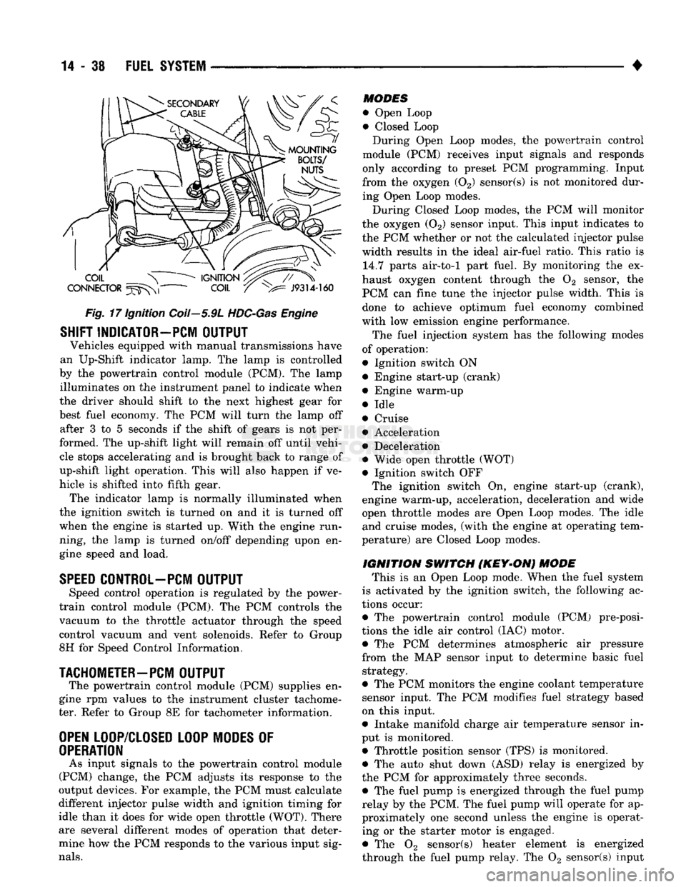
timing to meet changing engine operating conditions. The ignition coil is located near the front of the
right cylinder head (Fig. 16 or 17). Refer to Group 8D, Ignition System for additional
information.
Fig.
16 Ignition Coii-3.9U5.2U5.9L
LDC-Gas
Engine
SCI
TRANSMIT—PCM OUTPUT
SCI Transmit is the serial data communication
transmit circuit for the DRB II scan tool. The power- train control module (PCM) transmits data to the DRB II through the SCI Transmit circuit.
Page 857 of 1502
14 - 38
FUEL SYSTEM
•
Fig.
17 Ignition Coil—5.9L
HDC-Gas
Engine
SHIFT INDICATOR-PCM
OUTPUT
Vehicles equipped with manual transmissions have
an Up-Shift indicator lamp. The lamp is controlled
by the powertrain control module (PCM). The lamp illuminates on the instrument panel to indicate when
the driver should shift to the next highest gear for
best fuel economy. The PCM will turn the lamp off after 3 to 5 seconds if the shift of gears is not per
formed. The up-shift light will remain off until vehi cle stops accelerating and is brought back to range of
up-shift light operation. This will also happen if ve
hicle is shifted into fifth gear. The indicator lamp is normally illuminated when
the ignition switch is turned on and it is turned off
when the engine is started up. With the engine run
ning, the lamp is turned on/off depending upon en
gine speed and load.
SPEED
CONTROL-PCM
OUTPUT
Speed control operation is regulated by the power-
train control module (PCM). The PCM controls the
vacuum to the throttle actuator through the speed
control vacuum and vent solenoids. Refer to Group
8H for Speed Control Information.
TACHOMETER—PCM
OUTPUT
The powertrain control module (PCM) supplies en
gine rpm values to the instrument cluster tachome ter. Refer to Group 8E for tachometer information.
OPEN
LOOP/CLOSED LOOP MODES
OF
OPERATION
As input signals to the powertrain control module
(PCM) change, the PCM adjusts its response to the
output devices. For example, the PCM must calculate
different injector pulse width and ignition timing for
idle than it does for wide open throttle (WOT). There
are several different modes of operation that deter
mine how the PCM responds to the various input sig
nals.
MODES
• Open Loop
• Closed Loop During Open Loop modes, the powertrain control
module (PCM) receives input signals and responds
only according to preset PCM programming. Input
from the oxygen (02) sensor(s) is not monitored dur
ing Open Loop modes.
During Closed Loop modes, the PCM will monitor
the oxygen (02) sensor input. This input indicates to
the PCM whether or not the calculated injector pulse width results in the ideal air-fuel ratio. This ratio is 14.7 parts air-to-1 part fuel. By monitoring the ex
haust oxygen content through the 02 sensor, the
PCM can fine tune the injector pulse width. This is done to achieve optimum fuel economy combined
with low emission engine performance.
The fuel injection system has the following modes
of operation:
• Ignition switch ON • Engine start-up (crank)
• Engine warm-up
• Idle
• Cruise • Acceleration
• Deceleration
• Wide open throttle (WOT)
• Ignition switch OFF The ignition switch On, engine start-up (crank),
engine warm-up, acceleration, deceleration and wide
open throttle modes are Open Loop modes. The idle and cruise modes, (with the engine at operating tem
perature) are Closed Loop modes.
IGNITION
SWITCH
(KEY-ON)
MODE
This is an Open Loop mode. When the fuel system
is activated by the ignition switch, the following ac
tions occur:
• The powertrain control module (PCM) pre-posi-
tions the idle air control (IAC) motor. • The PCM determines atmospheric air pressure
from the MAP sensor input to determine basic fuel strategy.
• The PCM monitors the engine coolant temperature sensor input. The PCM modifies fuel strategy based
on this input.
• Intake manifold charge air temperature sensor in
put is monitored.
• Throttle position sensor (TPS) is monitored. • The auto shut down (ASD) relay is energized by
the PCM for approximately three seconds. • The fuel pump is energized through the fuel pump
relay by the PCM. The fuel pump will operate for ap
proximately one second unless the engine is operat ing or the starter motor is engaged.
• The 02 sensor(s) heater element is energized
through the fuel pump relay. The 02 sensor(s) input
Page 858 of 1502
•
FUEL SYSTEM
14 - 39 is not used by the PCM to calibrate air-fuel ratio
during this mode of operation,
• The up-shift indicator light is illuminated (manual
transmission only).
ENGINE
START-UP
MODE
This is an Open Loop mode. The following actions
occur when the starter motor is engaged.
The powertrain control module (PCM) receives in
puts from:
• Battery voltage
• Engine coolant temperature sensor • Crankshaft position sensor
• Intake manifold charge air temperature sensor • Manifold absolute pressure (MAP) sensor
• Throttle position sensor (TPS)
• Starter motor relay • Camshaft position sensor signal The PCM monitors the crankshaft position sensor.
If the PCM does not receive a crankshaft position sensor signal within 3 seconds of cranking the en
gine,
it will shut down the fuel injection system.
The fuel pump is activated by the PCM through
the fuel pump relay.
Voltage is applied to the fuel injectors with the
PCM. The PCM will then control the injection se quence and injector pulse width by turning the
ground circuit to each individual injector on and off.
The PCM determines the proper ignition timing ac
cording to input received from the crankshaft posi
tion sensor.
ENGINE
WARM-UP
MODE This is an Open Loop mode. During engine warm-
up,
the powertrain control module (PCM) receives in
puts from:
• Battery voltage • Crankshaft position sensor
• Engine coolant temperature sensor
• Intake manifold charge air temperature sensor • Manifold absolute pressure (MAP) sensor
• Throttle position sensor (TPS) • Camshaft position sensor signal (in the distributor)
• Park/Neutral switch (gear indicator signal—auto,
trans,
only)
• Air conditioning select signal (if equipped)
• Air conditioning request signal (if equipped) Based on these inputs the following occurs:
• Voltage is applied to the fuel injectors with the
powertrain control module (PCM). The PCM will
then control the injection sequence and injector pulse
width by turning the ground circuit to each individ ual injector on and off.
• The PCM adjusts engine idle speed through the
idle air control (IAC) motor and adjusts ignition tim
ing. • The PCM operates the A/C compressor clutch
through the clutch relay. This is done if A/C has
been selected by the vehicle operator and requested by the A/C thermostat.
• If the vehicle has a manual transmission, the up
shift light is operated by the PCM.
« When engine has reached operating temperature,
the PCM will begin monitoring 02 sensor(s) input.
The system will then leave the warm-up mode and go into closed loop operation.
IDLE
MODE
When the engine is at operating temperature, this
is a Closed Loop mode. At idle speed, the powertrain control module (PCM) receives inputs from:
Air conditioning select signal (if equipped)
• Air conditioning request signal (if equipped)
• Battery voltage
• Crankshaft position sensor
• Engine coolant temperature sensor • Intake manifold charge air temperature sensor
• Manifold absolute pressure (MAP) sensor
• Throttle position sensor (TPS)
• Camshaft position sensor signal (in the distributor)
® Battery voltage
• Park/Neutral switch (gear indicator signal—Auto,
trans,
only) • Oxygen sensor
Based on these inputs, the following occurs:
• Voltage is applied to the fuel injectors with the
powertrain control module (PCM). The PCM will
then control injection sequence and injector pulse
width by turning the ground circuit to each individ ual injector on and off.
• The PCM monitors the 02 sensor(s) input and ad
justs air-fuel ratio by varying injector pulse width. It also adjusts engine idle speed through the idle air
control (IAC) motor. • The PCM adjusts ignition timing by increasing and decreasing spark advance.
• The PCM operates the A/C compressor clutch
through the clutch relay. This happens if A/C has
been selected by the vehicle operator and requested
by the A/C thermostat.
CRUISE
MODE
When the engine is at operating temperature, this
is a Closed Loop mode. At cruising speed, the power-
train control module (PCM) receives inputs from:
• Air conditioning select signal (if equipped)
• Air conditioning request signal (if equipped)
• Battery voltage • Engine coolant temperature sensor
• Crankshaft position sensor
• Intake manifold charge air temperature sensor • Manifold absolute pressure (MAP) sensor
• Throttle position sensor (TPS)
• Camshaft position sensor signal (in the distributor)