EMISSION
CONTROL
SYSTEMS
25 - 13
For electrical tests
of the EET and its
circuitry,
re
fer
to the
appropriate Powertrain Diagnostic Proce dures service manual
for use of the DRB II
scan tool.
Refer
to the
Component Removal/Installation sec
tion
of
this group
for EET
replacement procedures.
OXYGEN
(02)
SENSOR
For description, operation, diagnosis
and
removal/
installation procedures
of the 02
sensor, refer
to
Group
14,
Fuel Systems.
AIR
INLET—5.9L
DIESEL
ENGINE
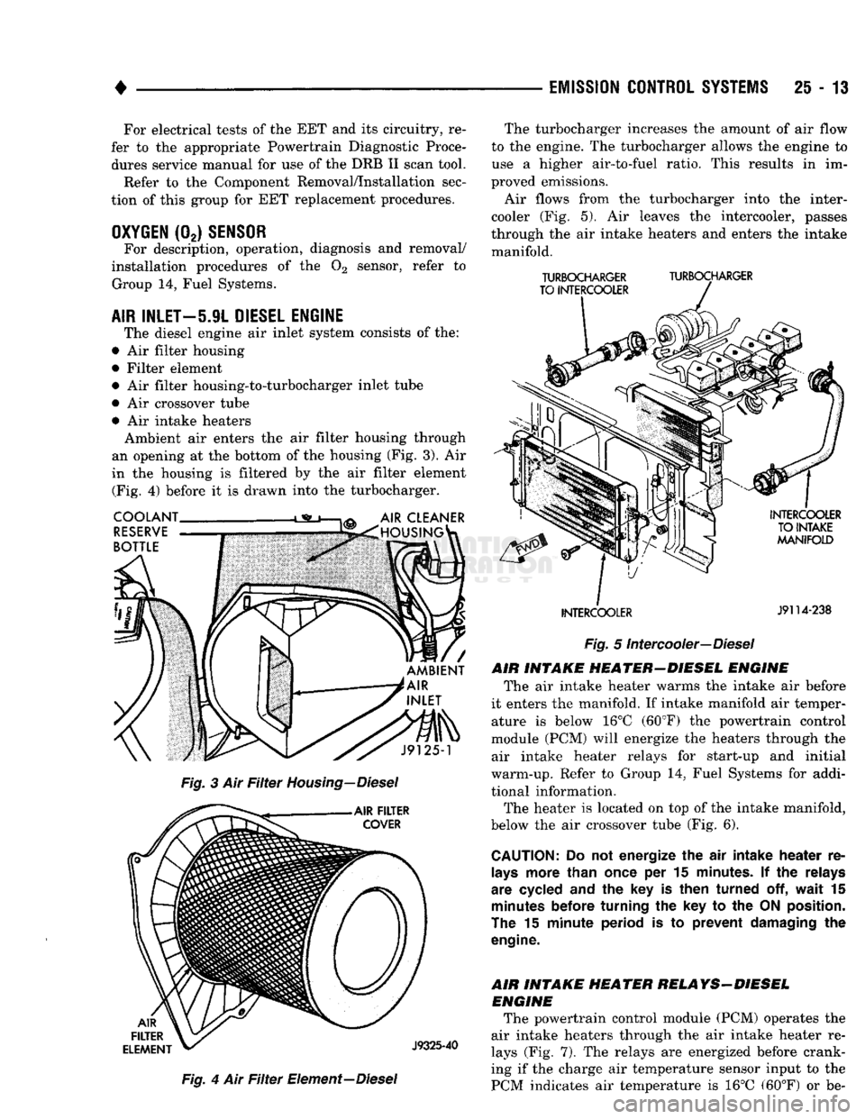
The diesel engine
air
inlet system consists
of the:
•
Air
filter housing
• Filter element •
Air
filter housing-to-turbocharger inlet tube
•
Air
crossover tube •
Air
intake heaters Ambient
air
enters
the air
filter housing through
an opening
at the
bottom
of the
housing
(Fig. 3). Air
in
the
housing
is
filtered
by the air
filter element (Fig.
4)
before
it is
drawn into
the
turbocharger.
Fig.
4 Air Filter
Element—Diesel The turbocharger increases
the
amount
of air
flow
to
the
engine.
The
turbocharger allows
the
engine
to
use
a
higher air-to-fuel ratio. This results
in im
proved emissions.
Air flows from
the
turbocharger into
the
inter-
cooler
(Fig. 5). Air
leaves
the
intercooler, passes
through
the air
intake heaters
and
enters
the
intake manifold.
TURBOCHARGER
TURBOCHARGER
TO INTERCOOLER
INTERCOOLER
J9114-238
Fig.
5
Intercooler—Diesel
AIR INTAKE HEATER-DIESEL ENGINE The
air
intake heater warms
the
intake
air
before
it enters
the
manifold.
If
intake manifold
air
temper ature
is
below
16°C
(60°F)
the
powertrain control
module
(PCM)
will energize
the
heaters through
the
air intake heater relays
for
start-up
and
initial
warm-up. Refer
to
Group
14,
Fuel Systems
for
addi
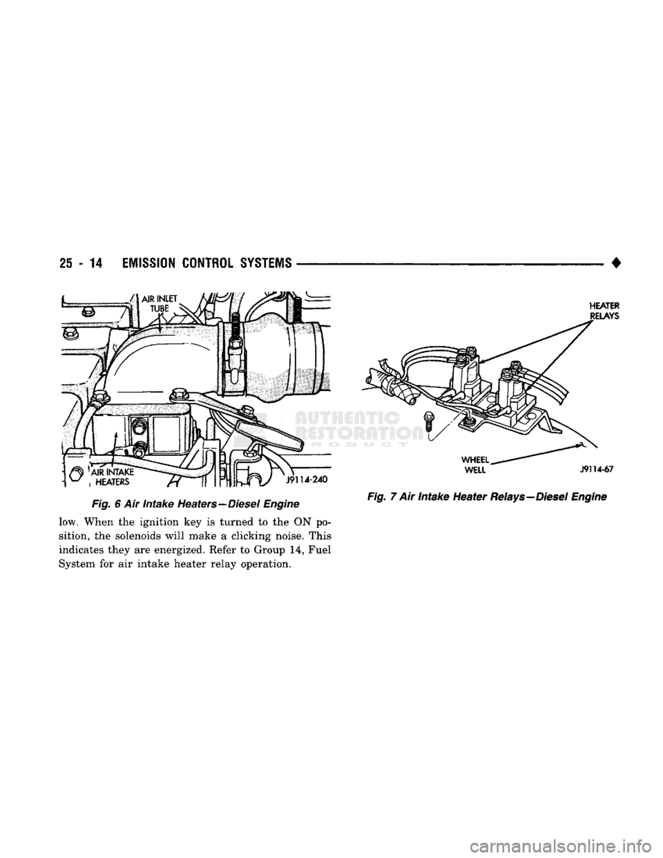
tional information. The heater
is
located
on top of the
intake manifold,
below
the air
crossover tube
(Fig. 6).
CAUTION:
Do not
energize
the air
intake heater
re
lays
more than once
per 15
minutes.
If the
relays
are cycled
and the key is
then turned
off,
wait
15
minutes
before turning
the key to the
ON
position.
The
15
minute period
is to
prevent damaging
the
engine.
AIR INTAKE HEATER RELAYS-DIESEL ENGINE The powertrain control module
(PCM)
operates
the
air intake heaters through
the air
intake heater
re
lays
(Fig. 7). The
relays
are
energized before crank
ing
if the
charge
air
temperature sensor input
to the
PCM indicates
air
temperature
is 16°C
(60°F)
or be-
25
- 14
EMISSION
CONTROL
SYSTEMS
HEATER
RELAYS
J9114-240
Fig.
6 Air
intake
Heaters—Diesel
Engine
low. When the ignition key is turned to the ON po
sition, the solenoids will make a clicking noise. This
indicates they are energized. Refer to Group 14, Fuel
System for air intake heater relay operation.
WHEEL
WELL
J9114-67
Fig.
7 Air Intake Heater
Relays—Diesel
Engine