1993 DODGE TRUCK oil change
[x] Cancel search: oil changePage 1191 of 1502
21
- 190
TRANSMISSION OVERHAUL—32RH
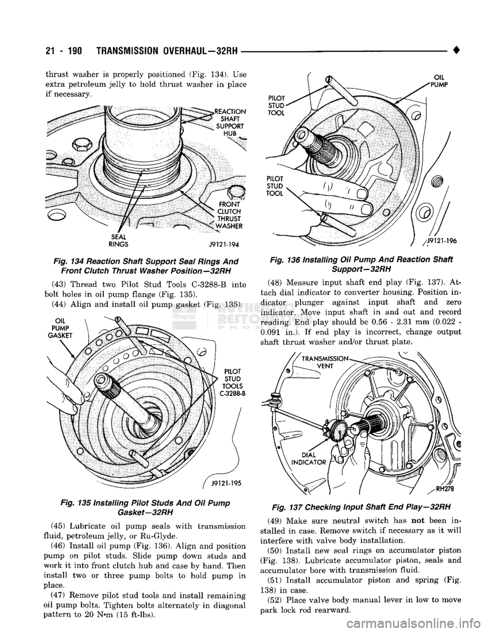
• thrust washer is properly positioned (Fig. 134). Use
extra petroleum jelly to hold thrust washer in place
if necessary.
SEAL
RINGS
J9121-194
Fig.
134 Reaction Shaft
Support
Seal
Rings
And Front
Clutch
Thrust
Washer
Position—32RH (43) Thread two Pilot Stud Tools C-32S8-B into
bolt holes in oil pump flange (Fig. 135).
(44) Align and install oil pump gasket (Fig. 135).
Fig.
135 Installing Pilot
Studs
And Oil
Pump
Gasket-32RH
(45) Lubricate oil pump seals with transmission
fluid, petroleum jelly, or Ru-Glyde.
(46) Install oil pump (Fig. 136). Align and position
pump on pilot studs. Slide pump down studs and
work it into front clutch hub and case by hand. Then install two or three pump bolts to hold pump in
place.
(47) Remove pilot stud tools and install remaining
oil pump bolts. Tighten bolts alternately in diagonal
pattern to 20 N-m (15 ft-lbs).
Fig.
136 Installing Oil
Pump
And Reaction Shaft
Support-32RH
(48) Measure input shaft end play (Fig. 137). At
tach dial indicator to converter housing. Position in dicator plunger against input shaft and zero
indicator. Move input shaft in and out and record
reading. End play should be 0.56 - 2.31 mm (0.022 - 0.091 in.). If end play is incorrect, change output
shaft thrust washer and/or thrust plate.
Fig.
137
Checking
Input Shaft End Play-32RH
(49) Make sure neutral switch has not been in
stalled in case. Remove switch if necessary as it will
interfere with valve body installation.
(50) Install new seal rings on accumulator piston
(Fig. 138). Lubricate accumulator piston, seals and
accumulator bore with transmission fluid. (51) Install accumulator piston and spring (Fig.
138) in case.
(52) Place valve body manual lever in low to move
park lock rod rearward.
Page 1221 of 1502
21
- 220
TRANSMISSION OVERHAUL—36RH/37RH
•
VALVE
BODY CLEANING AND INSPECTION
The only serviceable valve body components are
the:
• park lock rod and E-clip
• switch valve and spring
• pressure adjusting screw bracket
• throttle valve lever
• manual shaft
• manual shaft seal/washer/E-clip/detent ball
• fluid filter.
The remaining valve body components are serviced
only as part of a complete valve body assembly (Fig.
92).
Clean the valve body components in a parts clean
ing solution only. Do not use gasoline, kerosene, or
any type of caustic solution.
Dry the parts with compressed air. Make sure all
passages are clean and free from obstructions. Do not use rags or shop towels to dry or wipe
off valve body components unless they are made
from lint free material. Lint will adhere to the
valve body components causing valve bind. Lint
can also clog filters and small fluid passages.
Inspect the throttle and manual valve levers and
shafts.
Do not attempt to straighten a bent shaft
or correct a loose lever. Replace these compo
nents if worn, bent, loose or damaged in any way.
Inspect all of the valve body mating surfaces for
scratches, nicks, burrs, or distortion. Use a straight
edge to check surface flatness. Minor scratches may
be removed with crocus cloth using only very light pressure.
Minor distortion of a valve body mating surface
may be corrected by smoothing the surface with cro
cus cloth. Position the crocus cloth sheet on a surface
plate, sheet of plate glass, or equally flat surface. If distortion is severe or any surfaces are heavily
scored, the valve body will have to be replaced.
CAUTION:
The
throttle
valve, shuttle valve plug,
1-2
shift valve
and 1-2
governor plug
are
made
of
coated aluminum. Aluminum components
can be
identified
by the
dark color
of the
special coating
applied
to the
surface
(or by
testing
with
a
magnet).
DO
NOT
polish
or
sand
aluminum valves
or
plugs
with
any
type
of
material,
or
under
any
circum
stances.
This practice
will
remove
the
special coat
ing
and
cause
the
valves
and
plugs
to
stick
and
bind.
Inspect the valves and plugs for scratches, burrs,
nicks,
or scores. Also inspect the coating on the alu
minum valves and plugs. If the coating is damaged
or worn through, the valve (or valve body) should be
replaced.
Aluminum valves and plugs must not be sanded or
polished under any circumstances. However, minor burrs or scratches on steel valves and plugs can be
removed with crocus cloth but do not round off the
valve or plug edges. Squareness of these edges is vi
tally important; they prevent foreign matter from lodging between the valves and plugs and the bore.
Inspect all the valve and plug bores in the valve
body. Use a penlight to view the bore interiors. Re
place the valve body if any bores are distorted or scored. Inspect all of the valve body springs. The
springs must be free of distortion, warpage or broken
coils.
Trial fit each valve and plug in its bore to check
freedom of operation. When clean and dry, the valves and plugs should drop freely into the bores.
Valve body bores do not change dimensionally with
use.
If the valve body functioned correctly when new,
it will continue to operate properly after cleaning and inspection. It should not be necessary to replace a valve body assembly unless it is damaged in han
dling.
VALVE BODY ASSEMBLY
CAUTION:
Do not
force
the
valves
or
plugs
into place during reassembly.
If the
valve body bores
and
the
valves
and
plugs
are
free
of
distortion
or
burrs,
the
valves
and
plugs
should slide into place
easily.
In
addition,
do not
overtighten
the
transfer plate
and
valve body screws during reassembly.
Overtightening
can
distort
the
valve body resulting
in valve sticking,
cross
leakage
and
unsatisfactory
operation. Tighten
the
screws
alternately
and
evenly
to 4 Nnn (35 in.
lbs.) torque only.
(1) Lubricate valve body bores, valves and plugs
with ATF Plus, or Dexron II™ transmission fluid.
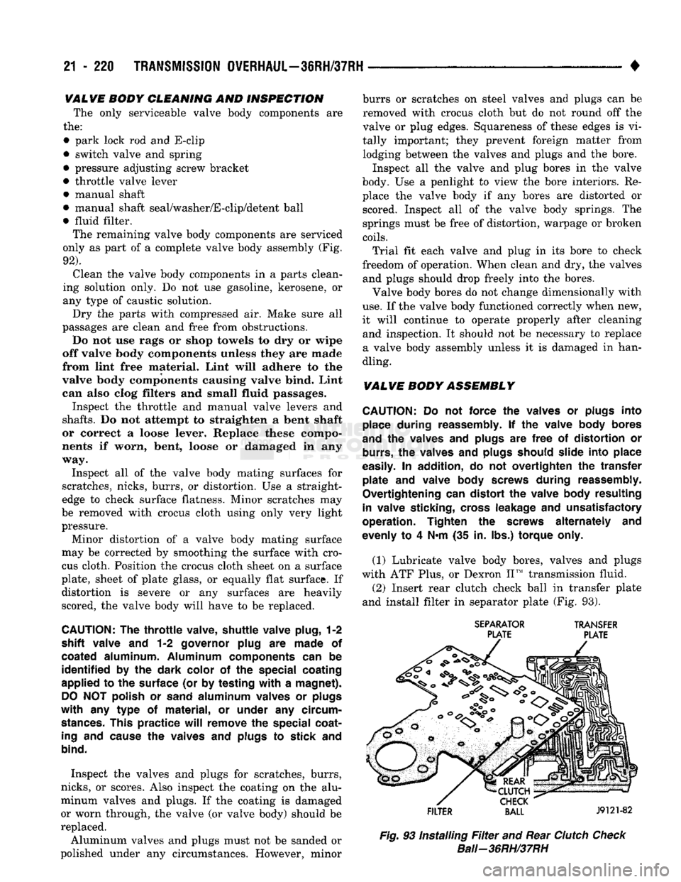
(2) Insert rear clutch check ball in transfer plate
and install filter in separator plate (Fig. 93).
SEPARATOR
TRANSFER
PLATE PLATE
FILTER
BALL
J9121-82
Fig.
93 Installing
Filter
and Rear
Clutch
Check
Bali—36RH/37RH
Page 1231 of 1502
21
- 230
TRANSMISSION
OWERHAUL-3IRH/37RH
•
J9121-103
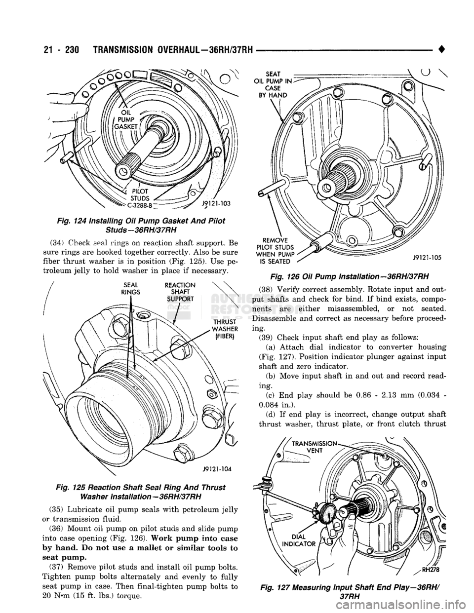
Fig.
124 Installing Oil
Pump
Gasket
And Pilot
Studs-36RH/37RH
(34) Check seal rings on reaction shaft support. Be
sure rings are hooked together correctly. Also be sure
fiber thrust washer is in position (Fig. 125). Use pe
troleum jelly to hold washer in place if necessary. J9121-104
Fig.
125 Reaction Shaft
Seal
Ring
And Thrust
Washer
Installation-36RH/37RH (35) Lubricate oil pump seals with petroleum jelly
or transmission fluid.
(36) Mount oil pump on pilot studs and slide pump
into case opening (Fig. 126). Work pump into case
by hand. Do not use a mallet or similar tools to seat pump.
(37) Remove pilot studs and install oil pump bolts.
Tighten pump bolts alternately and evenly to fully seat pump in case. Then final-tighten pump bolts to 20 Nnn (15 ft. lbs.) torque. SEAT
OIL PUMP IN
CASE
BY HAND
REMOVE
PILOT STUDS
WHEN PUMP IS SEATED J9121-105
Fig.
126 Oil
Pump
Installation-36RH/37RH (38) Verify correct assembly. Rotate input and out
put shafts and check for bind. If bind exists, compo nents are either misassembled, or not seated. Disassemble and correct as necessary before proceed
ing. (39) Check input shaft end play as follows: (a) Attach dial indicator to converter housing
(Fig. 127). Position indicator plunger against input
shaft and zero indicator. (b) Move input shaft in and out and record read
ing. (c) End play should be 0.86 - 2.13 mm (0.034 -
0.084 in.). (d) If end play is incorrect, change output shaft
thrust washer, thrust plate, or front clutch thrust
f
RH278
Fig.
127
Measuring
Input Shaft End Play—36RH/
37RH
Page 1265 of 1502
21
- 264
TRANSMISSION QVERHAUL-42RH
ADJUSTING
-
SCREW
AND
SWITCH
CONNECTOR
SEAL
J9321-226
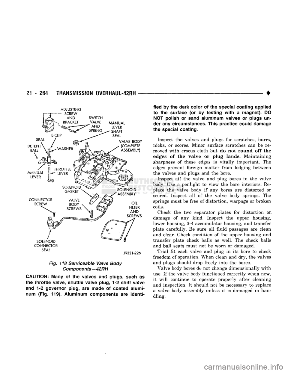
Fig. ! *8 Serviceable Valve
Body
Components—42RH
CAUTION;
Many
of the
waives
and
plugs,
such
as
the
throttle
valve,
shuttle
valve plug,
1-2 shift
valve
and
1-2
governor plug,
are
made
of
coated alumi num
(Fig. 119).
Aluminum components
are
identi
fied
by the
dark color
of the
special coating applied
to
the
surface
(or by
testing
with
a
magnet).
DO
NOT
polish
or
sand
aluminum valves
or
plugs
un
der
any
circumstances. This practice could damage
the special coating.
Inspect the valves and plugs for scratches, burrs,
nicks,
or scores. Minor surface scratches can be re
moved with crocus cloth but do not round off the
edges of the valve or plug lands. Maintaining sharpness of these edges is vitally important. The
edges prevent foreign matter from lodging between
the valves and plugs and the bore.
Inspect all the valve and plug bores in the valve
body. Use a penlight to view the bore interiors. Re place the valve body if any bores are distorted or scored. Inspect all of the valve body springs. The
springs must be free of distortion, warpage or broken
coils.
Check the two separator plates for distortion or.
damage of any kind. Inspect the upper housing,
lower housing,
3-4
accumulator housing, and transfer
plate carefully. Be sure all fluid passages are clean and clear. Check condition of the upper housing and
transfer plate check balls as well. The check balls and ball seats must not be worn or damaged.
Trial fit each valve and plug in its bore to check
freedom of operation. When clean and dry, the valves and plugs should drop freely into the bores.
Valve body bores do not change dimensionally with
use.
If the valve body functioned correctly when new,
it will continue to operate properly after cleaning and inspection. It should not be necessary to replace
a valve body assembly unless it is damaged in han
dling.
Page 1270 of 1502
•
TRANSMISSION
OVERHAUL-42RH
21 - 269 must be performed properly and in the correct se
quence. Line pressure is adjusted first and throttle
pressure is adjusted last.
Line
Pressure
Adjustment
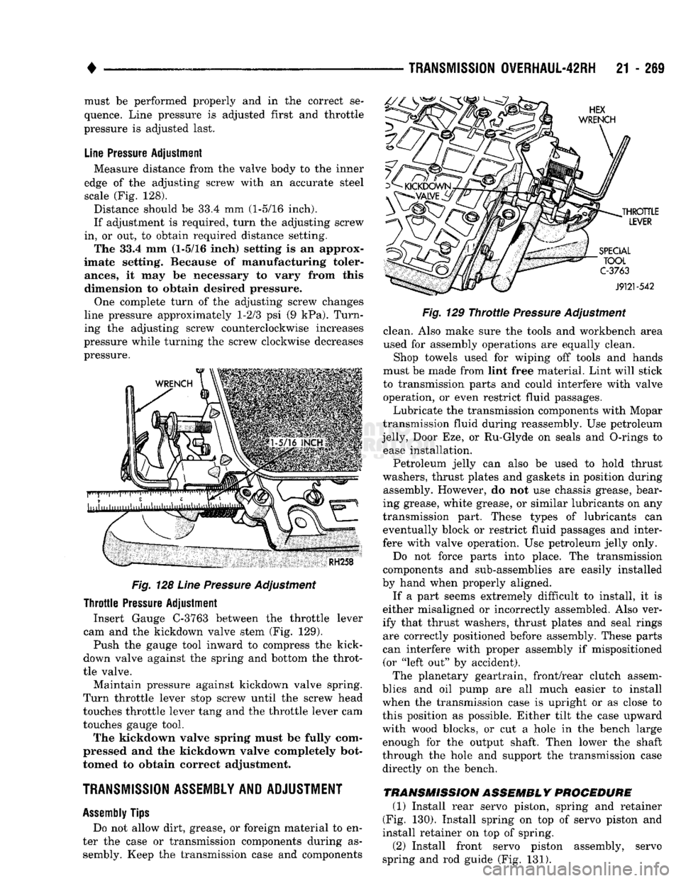
Measure distance from the valve body to the inner
edge of the adjusting screw with an accurate steel
scale (Fig. 128).
Distance should be 33.4 mm (1-5/16 inch).
If adjustment is required, turn the adjusting screw
in, or out, to obtain required distance setting. The 33.4 mm (1-5/16 inch) setting is an approx
imate setting. Because of manufacturing toler
ances,
it may be necessary to vary from this
dimension to obtain desired pressure.
One complete turn of the adjusting screw changes
line pressure approximately 1-2/3 psi (9 kPa). Turn
ing the adjusting screw counterclockwise increases
pressure while turning the screw clockwise decreases
pressure.
Fig.
128
Line
Pressure
Adjustment
Throttle
Pressure
Adjustment Insert Gauge C-3763 between the throttle lever
cam and the kickdown valve stem (Fig. 129).
Push the gauge tool inward to compress the kick-
down valve against the spring and bottom the throt
tle valve.
Maintain pressure against kickdown valve spring.
Turn throttle lever stop screw until the screw head
touches throttle lever tang and the throttle lever cam
touches gauge tool.
The kickdown valve spring must be fully com
pressed and the kickdown valve completely bot
tomed to obtain correct adjustment.
TRANSMISSION ASSEMBLY AND ADJUSTMENT
Assembly
Tips
Do not allow dirt, grease, or foreign material to en
ter the case or transmission components during as sembly. Keep the transmission case and components
Fig.
129
Throttie
Pressure
Adjustment
clean. Also make sure the tools and workbench area
used for assembly operations are equally clean.
Shop towels used for wiping off tools and hands
must be made from lint free material. Lint will stick
to transmission parts and could interfere with valve operation, or even restrict fluid passages.
Lubricate the transmission components with Mopar
transmission fluid during reassembly. Use petroleum
jelly, Door Eze, or Ru-Glyde on seals and O-rings to ease installation.
Petroleum jelly can also be used to hold thrust
washers, thrust plates and gaskets in position during assembly. However, do not use chassis grease, bear
ing grease, white grease, or similar lubricants on any
transmission part. These types of lubricants can eventually block or restrict fluid passages and inter
fere with valve operation. Use petroleum jelly only.
Do not force parts into place. The transmission
components and sub-assemblies are easily installed
by hand when properly aligned.
If a part seems extremely difficult to install, it is
either misaligned or incorrectly assembled. Also ver
ify that thrust washers, thrust plates and seal rings are correctly positioned before assembly. These parts
can interfere with proper assembly if mispositioned (or "left out" by accident).
The planetary geartrain, front/rear clutch assem
blies and oil pump are all much easier to install
when the transmission case is upright or as close to
this position as possible. Either tilt the case upward
with wood blocks, or cut a hole in the bench large enough for the output shaft. Then lower the shaft
through the hole and support the transmission case
directly on the bench.
TRANSMISSION ASSEMBLY PROCEDURE
(1) Install rear servo piston, spring and retainer
(Fig. 130). Install spring on top of servo piston and
install retainer on top of spring.
(2) Install front servo piston assembly, servo
spring and rod guide (Fig. 131).
Page 1334 of 1502
•
OVERDRIVE
UNIT
OVERHAUL—42RH/46RH
21 - 333 Check the machined surfaces on the output shaft.
These surfaces should clean and smooth. Very minor nicks or scratches can be smoothed with crocus cloth.
Replace the shaft if worn, scored or damaged in any
way.
Check condition of the governor components. Re
place the governor drive seal rings if damaged. Be sure the drive ring grooves are in good condition. Check operation of the governor valve, weights and
shaft. The valves and weights should slide freely in
the governor body (Fig. 36).
There are two governor component changes in
current overdrive unit units. The first involves
the governor valve which is now made of alumi
num. The second involves the output shaft which has a spotface for governor valve end
clearance. The new aluminum valve is not inter
changeable. It must only be used with an output
shaft that has the spotface for valve end clear ance.
Inspect the governor support and the two oil pres
sure tubes (Fig. 36). The tubes are an integral
part of the support. Do not attempt to remove
them.
The oil tubes must not be pinched, kinked, col
lapsed, or distorted. Blow them out with compressed
air to be sure they are clear. The tubes are designed
to be a slip fit in the piston retainer boss. Do not modify the tube ends in an effort to make them fit
tighter.
Replace the governor support and the oil tubes as
an assembly if either component is damaged.
Check condition of the governor valve and weight
snap rings. Replace any snap ring that appears bent
or distorted. Replace any snap ring if its condition is
doubtful.
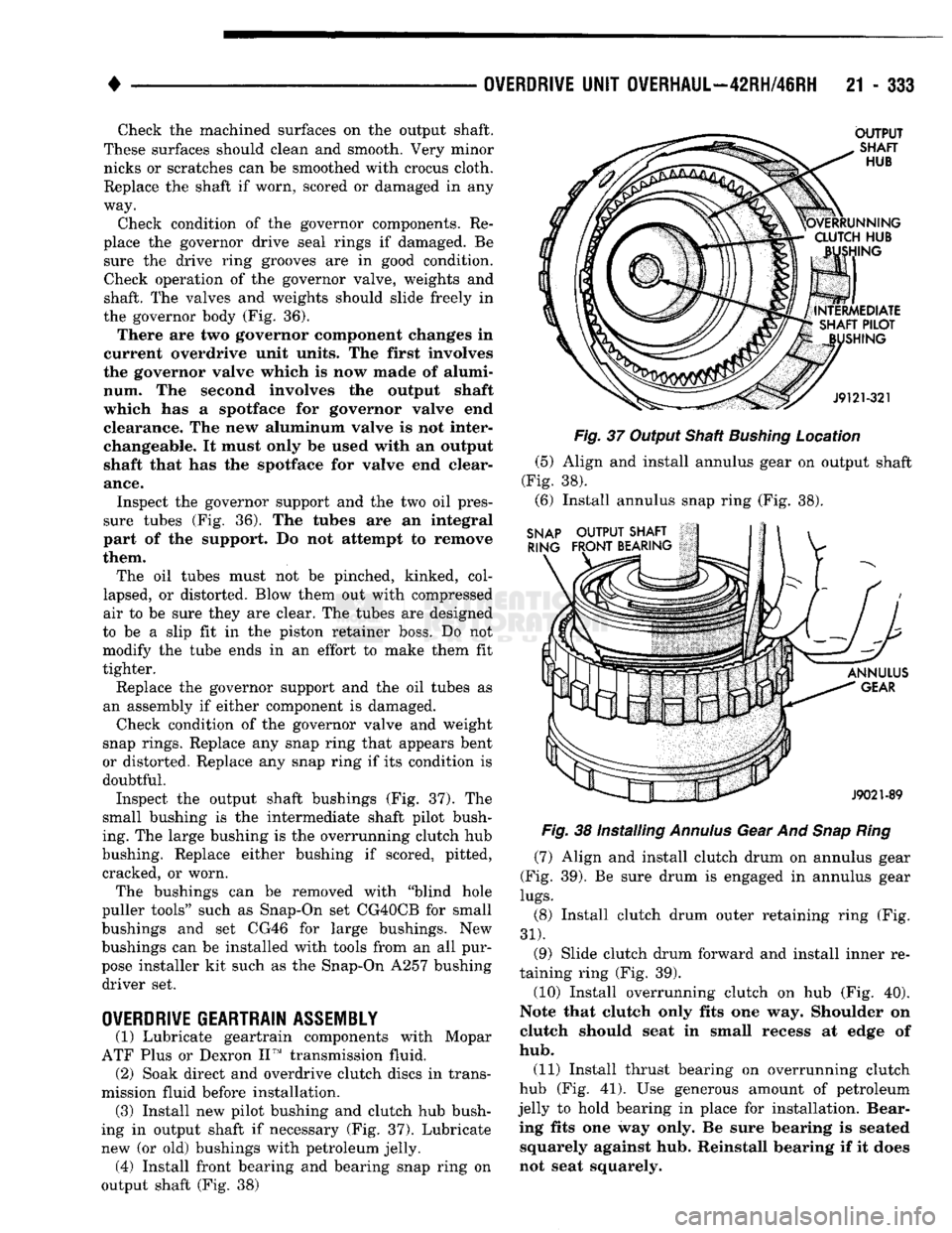
Inspect the output shaft bushings (Fig. 37). The
small bushing is the intermediate shaft pilot bush
ing. The large bushing is the overrunning clutch hub
bushing. Replace either bushing if scored, pitted, cracked, or worn.
The bushings can be removed with "blind hole
puller tools" such as Snap-On set CG40CB for small
bushings and set CG46 for large bushings. New
bushings can be installed with tools from an all pur
pose installer kit such as the Snap-On A257 bushing driver set.
OVERDRIVE
GEARTRAIN
ASSEMBLY
(1) Lubricate geartrain components with Mopar
ATF Plus or Dexron II™ transmission fluid. (2) Soak direct and overdrive clutch discs in trans
mission fluid before installation. (3) Install new pilot bushing and clutch hub bush
ing in output shaft if necessary (Fig. 37). Lubricate
new (or old) bushings with petroleum jelly. (4) Install front bearing and bearing snap ring on
output shaft (Fig. 38)
Fig.
37 Output Shaft
Bushing
Location
(5) Align and install annulus gear on output shaft
(Fig. 38). (6) Install annulus snap ring (Fig. 38).
Fig.
38 Installing
Annulus
Gear And
Snap Ring
(7) Align and install clutch drum on annulus gear
(Fig. 39). Be sure drum is engaged in annulus gear
lugs.
(8) Install clutch drum outer retaining ring (Fig.
31).
(9) Slide clutch drum forward and install inner re
taining ring (Fig. 39).
(10) Install overrunning clutch on hub (Fig. 40).
Note that clutch only fits one way. Shoulder on
clutch should seat in small recess at edge of
hub.
(11) Install thrust bearing on overrunning clutch
hub (Fig. 41). Use generous amount of petroleum
jelly to hold bearing in place for installation. Bear ing fits one way only. Be sure bearing is seated squarely against hub. Reinstall bearing if it does
not seat squarely.
Page 1367 of 1502
21 • 366
TRANSMISSION/TRANSFER
CASE
SPECIFICATIONS
•
Overdrive Clutch
Fourth Gear Only Pressure should be
469-496
kPa
(68-72
psi) with closed throttle and increase to
620-896
kPa
(90-130
psi) at 1/2 to 3/4 throttle.
Line Pressure
(at accumulator) Closed Throttle
1000
rpm and above
372-414
kPa
(54-60
psi)
648 kPa (94 psi)
Front Servo Third Gear Only No more than
21
kPa (3 psi) lower than line pressure.
Rear Servo
1
Range
R Range No more then
21
kPa (3 psi) lower than line pressure. 1103 kPa (160 psi) at idle,
builds to 1862 kPa (270 psi) at 1600 rpm.
Governor D Range
Closed Throttle Pressure should respond smoothly to changes in mph and return to 0-7 kPa
(0-1
Vi
psi) when stopped with transmission in D,
1,
2. Pressure
above
7
kPa
(IV2
psi)
at
standstill
will
prevent
transmission
from
downshifting.
J9321-192
AUTOMATIC
TRANSMISSION
TORQUE
SPECIFICATIONS
DESCRIPTION TORQUE DESCRIPTION TORQUE
Cooler Line Fittings 18 N-m (13 ft. lbs.)
Converter Bolts: 9.5 in.,
3-lug
converter 54 N-m (40 ft. lbs.
9.5 in., 4-lug converter 74 N-m (55 ft. lbs. 10.0 in., 4-lug converter 74 N-m (55 ft. lbs.
10.75 in., 4-lug converter 31 N-m (270 in. lbs.
Crossmember Bolts/Nuts 68 N-m (50 ft. lbs. Driveplate Bolts 75 N-m (55 ft. lbs.
Extension Housing Bolts 43 N-m (32 ft. lbs.
Front Band Reaction Pin Access Plug 17 N-m (13 ft. lbs.
Front Band Adjusting Screw Locknut 34 N-m (25 ft. lbs.
Governor Body-to-Park Gear Bolts 11 N-m (8 ft. lbs.
Lockup Module Screws 4 N-m (35 in. lbs.
Neutral Switch 34 N-m (25 ft. lbs.
Oil Filter Screws 4 N-m (35 in. lbs.
Oil Pan Bolt 17 N-m (13 ft. lbs.
Oil Pump Bolt 20 N-m (15 ft. lbs.
Overrunning Clutch Cam Set Screw (36RH/46RH) 5 N-m (40 in. lbs. Overrunning Clutch Cam Bolts 17 N-m (150 in. lbs.
Overdrive Compounder-to- Transmission Case Bolts 34 N-m (25 ft. lbs.
Overdrive Piston Retainer Bolts (42RH/46RH) 17 N-m (150 in. lbs.
Pressure Test Port Plugs 14 N-m (10 ft. lbs.
Propeller Shaft Clamp Bolts 19 N-m (170 in. lbs.
Reaction Shaft Support Bolts 20 N-m (15 ft. lbs.
Rear
Band
Adjusting Screw Locknut 41 N-m (30 ft. lbs.
Rear Mount Bolts/Nuts 68 N-m (50 ft. lbs.
Rear Support Bolts (32RH/36RH) 17 N-m (150 in. lbs.
Solenoid Wiring Connector Screw 17 N-m (13 ft. lbs.
Solenoid-to-Transfer Plate Screw 4 N-m (35 in. lbs.
Speedometer Adapter Bolt 11 N-m (8 ft. lbs.
Valve Body Housing Screws 4 N-m (35 in. lbs.
Valve Body-to-Case Bolts 12 N-m (100 in. lbs.
J9221-157
AUTOMATIC TRANSMISSION PRESSURE TEST SPECIFICATIONS (42RH/46RH)
Page 1464 of 1502
•
HEATING
AND AIR
CONDITIONING
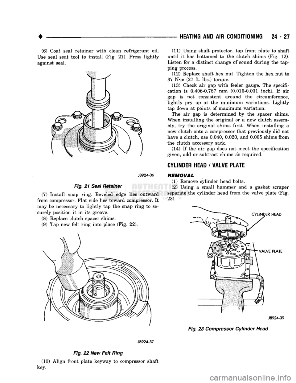
24 - 27 (6) Coat seal retainer with clean refrigerant oil.
Use seal seat tool to install (Fig. 21). Press lightly against seal.
J8924-36
Fig.
21
Seal
Retainer
(7) Install snap ring. Beveled edge lies outward
from compressor. Flat side lies toward compressor. It
may be necessary to lightly tap the snap ring to se curely position it in its groove.
(8) Replace clutch spacer shims.
(9) Tap new felt ring into place (Fig. 22).
J8924-37
Fig.
22 New
Felt
Ring
(10) Align front plate keyway to compressor shaft
key. (11) Using shaft protector, tap front plate to shaft
until it has bottomed to the clutch shims (Fig. 12).
Listen for a distinct change of sound during the tap
ping process.
(12) Replace shaft hex nut. Tighten the hex nut to
37 N-m (27 ft. lbs.) torque.
(13) Check air gap with feeler gauge. The specifi
cation is 0.406-0.787 mm (0.016-0.031 inch). If air
gap is not consistent around the circumference,
lightly pry up at the minimum variations. Lightly
tap down at points of maximum variation.
The air gap is determined by the spacer shims.
When installing the original or a new clutch assem
bly, try the original shims first. When installing a new clutch onto a compressor that previously did not
have a clutch, use 0.040, 0.020, and 0.005 shims from
the clutch accessory sack.
(14) If the air gap does not meet the specification
given, add or subtract shims as required.
CYLINDER
HEAD
/
VALVE PLATE
REMOVAL
(1) Remove cylinder head bolts.
(2) Using a small hammer and a gasket scraper
separate the cylinder head from the valve plate (Fig.
23).
J8924-39
Fig.
23
Compressor
Cylinder Head