1993 DODGE TRUCK oil change
[x] Cancel search: oil changePage 672 of 1502
•
5.2L
ENGINE
I - 67
DIAMETER
(D)
SHOULD
BE
0.0000-0.0152
mm
(0.0000-0.0006
in.)
LARGER
THAN
(C).
98.704-98.831
mm
•
(3.886-3.891
in.)-
FEELER
GAUGE
62.230
mm (2.45 in.)
1
26.543
mm
(1.045
in.)
±c
ELLIPTICAL
SHAPE
OF
THE
PISTON
SKIRT
SHOULD
BE
0.254-0.304
mm
(0.010-0.012
in.)
LESS AT
DIAMETER
(A)
THAN
ACROSS
THE
THRUST
FACES
AT
DIAMETER
(B).
J9309-9
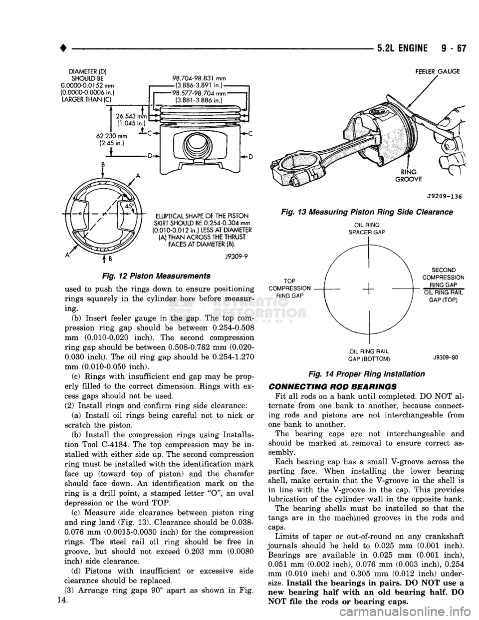
Fig.
12
Piston
Measurements
used to push the rings down to ensure positioning
rings squarely in the cylinder bore before measur ing.
(b) Insert feeler gauge in the gap. The top com
pression ring gap should be between 0.254-0.508 mm (0.010-0.020 inch). The second compression
ring gap should be between 0.508-0.762 mm (0.020-0.030 inch). The oil ring gap should be 0.254-1.270
mm (0.010-0.050 inch).
(c) Rings with insufficient end gap may be prop
erly filled to the correct dimension. Rings with ex cess gaps should not be used.
(2) Install rings and confirm ring side clearance: (a) Install oil rings being careful not to nick or
scratch the piston.
(b) Install the compression rings using Installa
tion Tool C-4184. The top compression may be in stalled with either side up. The second compression
ring must be installed with the identification mark
face up (toward top of piston) and the chamfer should face down. An identification mark on the
ring is a drill point, a stamped letter "O", an oval
depression or the word TOP.
(c) Measure side clearance between piston ring
and ring land (Fig. 13). Clearance should be 0.038-
0.076 mm (0.0015-0.0030 inch) for the compression
rings.
The steel rail oil ring should be free in
groove, but should not exceed 0.203 mm (0.0080
inch) side clearance.
(d) Pistons with insufficient or excessive side
clearance should be replaced. (3) Arrange ring gaps 90° apart as shown in Fig.
RING
GROOVE
J9209-136
Fig.
13
Measuring
Piston
Ring
Side
Clearance
OIL
RING
SPACER
GAP
TOP
COMPRESSION
RING
GAP
SECOND
COMPRESSION
RING
GAP
OIL
RING
RAIL
GAP (TOP) OIL
RING
RAIL
GAP
(BOTTOM)
J9309-80
14. Fig.
14 Proper
Ring
Installation
CONNECTING
ROD
BEARINGS
Fit all rods on a bank until completed. DO NOT al
ternate from one bank to another, because connect ing rods and pistons are not interchangeable from
one bank to another.
The bearing caps are not interchangeable and
should be marked at removal to ensure correct as
sembly.
Each bearing cap has a small V-groove across the
parting face. When installing the lower bearing shell, make certain that the V-groove in the shell is
in line with the V-groove in the cap. This provides
lubrication of the cylinder wall in the opposite bank.
The bearing shells must be installed so that the
tangs are in the machined grooves in the rods and
caps.
Limits of taper or out-of-round on any crankshaft
journals should be held to 0.025 mm (0.001 inch). Bearings are available in 0.025 mm (0.001 inch), 0.051 mm (0.002 inch), 0.076 mm (0.003 inch), 0.254
mm (0.010 inch) and 0.305 mm (0.012 inch) under
size.
Install the bearings in pairs. DO NOT use a
new bearing half with an old bearing
half.
DO
NOT file the rods or bearing caps.
Page 673 of 1502
9
- 68 5.2L
ENGINE
• INSTALLATION
(1) Be sure that compression ring gaps are stag
gered so that neither is in-line with oil ring rail gap.
(2) Before installing the ring compressor, make
sure the oil ring expander ends are butted and the
rail gaps located properly (Fig. 14).
(3) Immerse the piston head and rings in clean en
gine oil. Slide Piston Ring Compressor Tool C-385
over the piston and tighten with the special wrench (part of Tool C-385). Be sure position of rings does
not change during this operation.
(4) Install connecting rod bolt protectors on rod
bolts,
the long protector should be installed on the numbered side of the connecting rod. (5) Rotate crankshaft so that the connecting rod
journal is on the center of the cylinder bore. Be sure connecting rod and cylinder bore number are the same. Insert rod and piston into cylinder bore and
guide rod over the crankshaft journal.
(6) Tap the piston down in cylinder bore, using a
hammer handle. At the same time, guide connecting rod into position on crankshaft journal.
(7) The notch or groove on top of piston must be
pointing toward front of engine. The larger chamfer
of the connecting rod bore must be installed toward
crankshaft journal fillet.
(8) Install rod caps. Be sure connecting rod, con
necting rod cap and cylinder bore number are the same. Install nuts on cleaned and oiled rod bolts and
tighten nuts to 61 N®m (45 ft. lbs.) torque.
(9) Install the oil pan.
(10) Install the cylinder head.
(11) Install the engine into the vehicle.
CRANKSHAFT
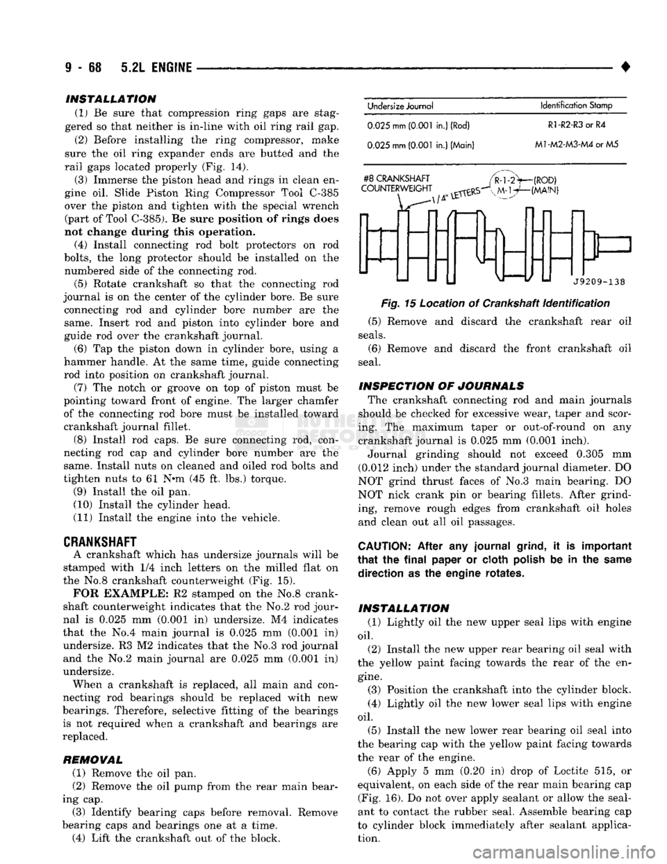
A crankshaft which has undersize journals will be
stamped with 1/4 inch letters on the milled flat on
the No.8 crankshaft counterweight (Fig. 15).
FOR
EXAMPLE: R2 stamped on the No.8 crank
shaft counterweight indicates that the No.2 rod jour
nal is 0.025 mm (0.001 in) undersize. M4 indicates
that the No.4 main journal is 0.025 mm (0.001 in) undersize. R3 M2 indicates that the No.3 rod journal and the No.2 main journal are 0.025 mm (0.Q01 in)
undersize. When a crankshaft is replaced, all main and con
necting rod bearings should be replaced with new
bearings. Therefore, selective fitting of the bearings is not required when a crankshaft and bearings are
replaced.
REMOVAL (1) Remove the oil pan.
(2) Remove the oil pump from the rear main bear
ing cap. (3) Identify bearing caps before removal. Remove
bearing caps and bearings one at a time. (4) Lift the crankshaft out of the block.
Undersize
Journal
Identification
Stamp
0.025
mm
(0.001
in.)
(Rod)
R1-R2-R3
or R4
0.025
mm
(0.001
in.) (Main)
M1-M2-M3-M4
or M5
#8
CRANKSHAFT
COUNTERWEIGHT
(ROD)
(MAIN)
f
J9209-138
Fig.
15 Location of Crankshaft
Identification
(5) Remove and discard the crankshaft rear oil
seals.
(6) Remove and discard the front crankshaft oil
seal.
INSPECTION OF JOURNALS The crankshaft connecting rod and main journals
should be checked for excessive wear, taper and scor
ing. The maximum taper or out-of-round on any crankshaft journal is 0.025 mm (0.001 inch). Journal grinding should not exceed 0.305 mm
(0.012 inch) under the standard journal diameter. DO
NOT grind thrust faces of No.3 main bearing. DO
NOT nick crank pin or bearing fillets. After grind ing, remove rough edges from crankshaft oil holes
and clean out all oil passages.
CAUTION:
After any journal
grind,
it is important
that
the
final
paper or cloth
polish
be in the
same
direction as the engine rotates.
INSTALLATION (1) Lightly oil the new upper seal lips with engine
oil.
(2) Install the new upper rear bearing oil seal with
the yellow paint facing towards the rear of the en
gine.
(3) Position the crankshaft into the cylinder block.
(4) Lightly oil the new lower seal lips with engine
oil.
(5) Install the new lower rear bearing oil seal into
the bearing cap with the yellow paint facing towards
the rear of the engine.
(6)
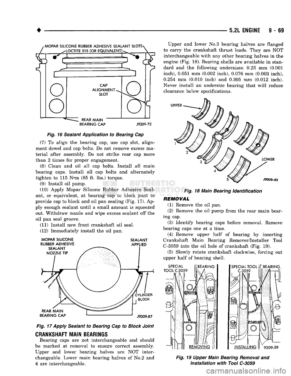
Apply 5 mm (0.20 in) drop of Loctite 515, or
equivalent, on each side of the rear main bearing cap (Fig. 16). Do not over apply sealant or allow the seal
ant to contact the rubber seal. Assemble bearing cap
to cylinder block immediately after sealant applica tion.
Page 674 of 1502
5.2L ENGINE
9 - 69
BEARING
CAP
J9309-72
Fig.
16 Sealant Application to Bearing Cap (7) To align the bearing cap, use cap slot, align
ment dowel and cap bolts. Do not remove excess ma
terial after assembly. Do not strike rear cap more
than 2 times for proper engagement.
(8) Clean and oil all cap bolts. Install all main
bearing caps. Install all cap bolts and alternately
tighten to 115 Nnn (85 ft. lbs.) torque.
(9) Install oil pump.
(10) Apply Mopar Silicone Rubber Adhesive Seal
ant, or equivalent, at bearing cap to block joint to
provide cap to block and oil pan sealing (Fig. 17). Ap
ply enough sealant until a small amount is squeezed out. Withdraw nozzle and wipe excess sealant off the
oil pan seal groove.
(11) Install new front crankshaft oil seal.
(12) Immediately install the oil pan.
MOPAR SILICONE SEALANT
RUBBER
ADHESIVE APPLIED
Fig.
17
Apply
Sealant to Bearing Cap to
Block
Joint
CRANKSHAFT
MAIN BEARINGS
Bearing caps are not interchangeable and should
be marked at removal to ensure correct assembly.
Upper and lower bearing halves are NOT inter changeable. Lower main bearing halves of No.2 and
4
are interchangeable. Upper and lower No.3 bearing halves are flanged
to carry the crankshaft thrust loads. They are NOT interchangeable with any other bearing halves in the
engine (Fig. 18). Bearing shells are available in stan
dard and the following under
sizes:
0.25 mm (0.001
inch),
0.051 mm (0.002 inch), 0.076 mm (0.003 inch),
0.254 mm (0.010 inch) and 0.305 mm (0.012 inch).
Never install an undersize bearing that will reduce
clearance below specifications.
Fig.
18 Main Bearing
Identification
REMOVAL (1) Remove the oil pan.
(2) Remove the oil pump from the rear main bear
ing cap.
(3) Identify bearing caps before removal. Remove
bearing caps one at a time.
(4) Remove upper half of bearing by inserting
Crankshaft Main Bearing Remover/Installer Tool
C-3059 into the oil hole of crankshaft (Fig. 19).
(5) Slowly rotate crankshaft clockwise, forcing out
upper half of bearing shell.
Fig.
19 Upper Main Bearing
Removal
and
Installation
with
Tool C-3059
Page 693 of 1502
9
- 88 5.9L
ENGINE
•
CAUTION:
The
plunger
and
tappet
bodies
are not
interchangeable,.
The
plunger
and
valve must
al
ways
be
fitted
to the
original
body,
It is
advisable
to
work
on one
tappet
at a time to
avoid mixing
of
parts. Mixed parts
are not
compatible.
DO
NOT dis
assemble
a
tappet
on a dirty
work bench.
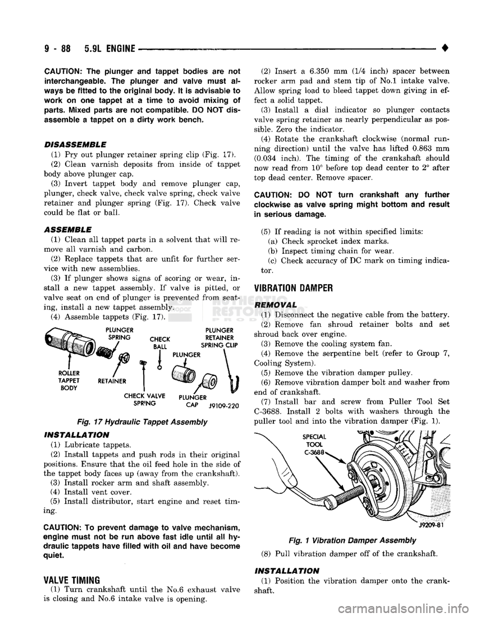
DISASSEMBLE (1) Pry out plunger retainer spring clip (Fig. 17).
(2) Clean varnish deposits from inside of tappet
body above plunger cap.
(3) Invert tappet body and remove plunger cap,
plunger, check valve, check valve spring, check valve
retainer and plunger spring (Fig, 17). Check valve
could be flat or ball.
ASSEMBLE
(1) Clean all tappet parts in a solvent that will re
move all varnish and carbon. (2) Replace tappets that are unfit for further ser
vice with new assemblies.
(3) If plunger shows signs of scoring or wear, in
stall a new tappet assembly. If valve is pitted, or
valve seat on end of plunger is prevented from seat ing, install a new tappet assembly.
(4) Assemble tappets (Fig. 17).
SPiING
CAP J9109-220
Fig.
17 Hydraulic
Tappet
Assembly INSTALLATION
(1) Lubricate tappets.
(2) Install tappets and push rods in their original
positions. Ensure that the oil feed hole In the side of
the tappet body faces up (away from the crankshaft). (3) Install rocker arm and shaft assembly.
(4) Install vent cover.
(5) Install distributor, start engine and reset tim
ing.
CAUTION:
To
prevent damage
to
valve mechanism,
engine must
not be run
above
fast
idle
until
all hy
draulic tappets have
filled
with oil and
have become
quiet.
¥AL¥E
TIMING
(1) Turn crankshaft until the No.6 exhaust valve
is closing and No.6 intake valve Is opening. (2) Insert a 6.350 mm (1/4 inch) spacer between
rocker arm pad and stem tip of No.l intake valve.
Allow spring load to bleed tappet down giving in ef
fect a solid tappet. (3) Install a dial indicator so plunger contacts
valve spring retainer as nearly perpendicular as pos
sible.
Zero the Indicator.
(4) Rotate the crankshaft clockwise (normal run
ning direction) until the valve has lifted 0.863 mm (0.034 inch). The timing of the crankshaft should
now read from 10° before top dead center to 2° after
top dead center. Remove spacer.
CAUTION:
DO NOT
turn crankshaft
any
further
clockwise
as
valve spring might bottom
and
result
in serious damage.
(5) If reading is not within specified limits: (a) Check sprocket index marks.
(b) Inspect timing chain for wear.
(c) Check accuracy of DC mark on timing indica
tor. -
¥IBRATI0N
PAMPER
REMOVAL (1) Disconnect the negative cable from the battery.
(2) Remove fan shroud retainer bolts and set
shroud back over engine. (3) Remove the cooling system fan.
(4) Remove the serpentine belt (refer to Group 7,
Cooling System). (5) Remove the vibration damper pulley. (6) Remove vibration damper bolt and washer from
end of crankshaft. (7) Install bar and screw from Puller Tool Set
C-3688. Install 2 bolts with washers through the
puller tool and into the vibration damper (Fig. 1).
J9209-81
Fig.
1
Vibration
Damper
Assembly
(8) Pull vibration damper off of the crankshaft.
INSTALLATION (1) Position the vibration damper onto the crank
shaft.
Page 697 of 1502
9
- 92 5.9L
ENGINE
•
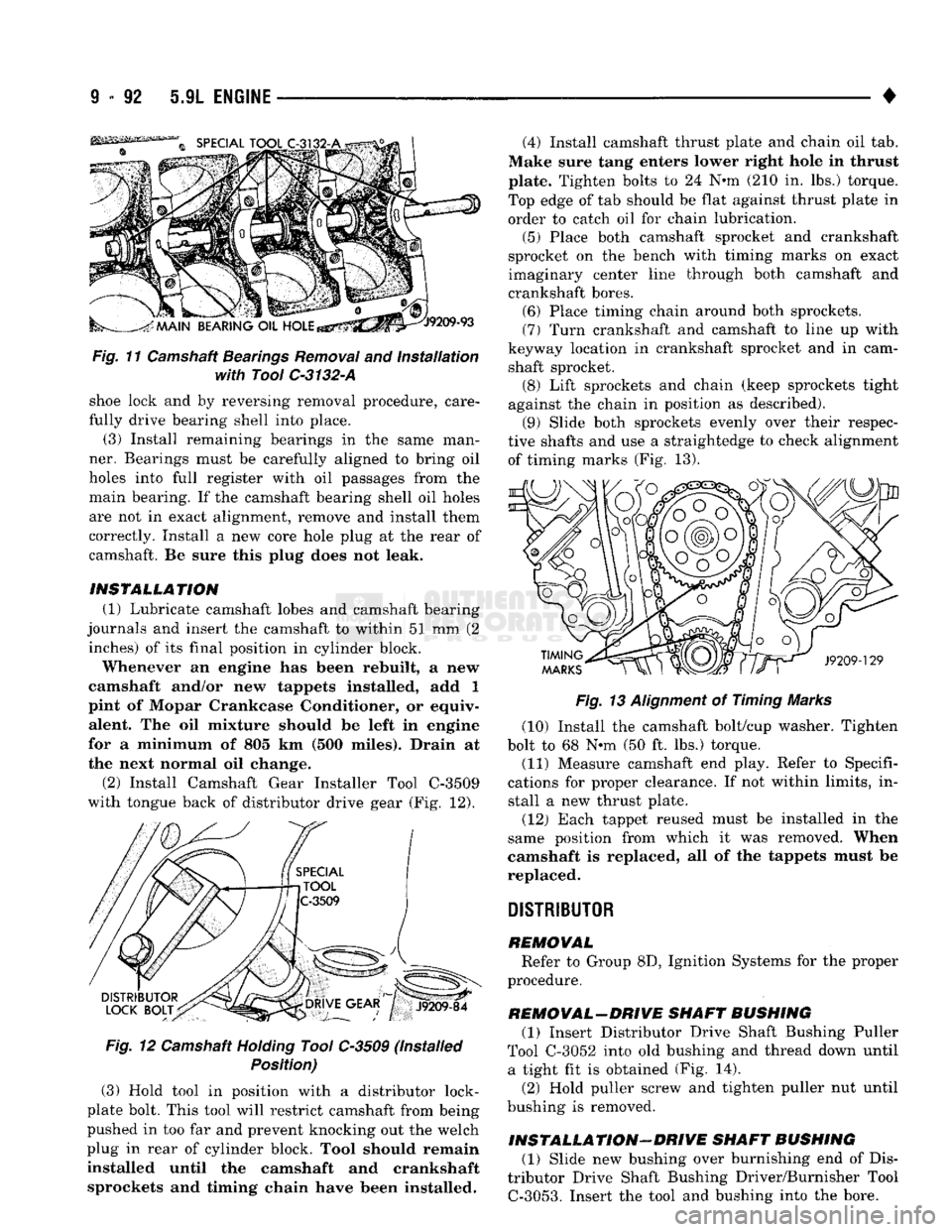
Fig.
11 Camshaft
Bearings
Removal
and
Installation
with Tool
C-3132-A
shoe lock and by reversing removal procedure, care
fully drive bearing shell into place. (3) Install remaining bearings in the same man
ner. Bearings must be carefully aligned to bring oil
holes into full register with oil passages from the main bearing. If the camshaft bearing shell oil holes
are not in exact alignment, remove and install them
correctly. Install a new core hole plug at the rear of
camshaft. Be sure this plug does not leak.
INSTALLATION (1) Lubricate camshaft lobes and camshaft bearing
journals and insert the camshaft to within 51 mm (2 inches) of its final position in cylinder block.
Whenever an engine has been rebuilt, a new
camshaft and/or new tappets installed, add 1
pint of Mopar Crankcase Conditioner, or equiv alent. The oil mixture should be left in engine
for a minimum of 805 km (500 miles). Drain at
the next normal oil change.
(2)
Install Camshaft Gear Installer Tool C-3509
with tongue back of distributor drive gear (Fig. 12).
Fig.
12 Camshaft
Holding
Tool C-3509 (Installed
Position)
(3) Hold tool in position with a distributor lock-
plate bolt. This tool will restrict camshaft from being
pushed in too far and prevent knocking out the welch
plug in rear of cylinder block. Tool should remain
installed until the camshaft and crankshaft sprockets and timing chain have been installed. (4) Install camshaft thrust plate and chain oil tab.
Make sure tang enters lower right hole in thrust
plate. Tighten bolts to 24 N-m (210 in. lbs.) torque.
Top edge of tab should be flat against thrust plate in
order to catch oil for chain lubrication.
(5) Place both camshaft sprocket and crankshaft
sprocket on the bench with timing marks on exact
imaginary center line through both camshaft and
crankshaft bores. (6) Place timing chain around both sprockets.
(7) Turn crankshaft and camshaft to line up with
keyway location in crankshaft sprocket and in cam shaft sprocket. (8) Lift sprockets and chain (keep sprockets tight
against the chain in position as described). (9) Slide both sprockets evenly over their respec
tive shafts and use a straightedge to check alignment of timing marks (Fig. 13).
Fig.
13
Alignment
of Timing Marks
(10) Install the camshaft bolt/cup washer. Tighten
bolt to 68 N-m (50 ft. lbs.) torque.
(11) Measure camshaft end play. Refer to Specifi
cations for proper clearance. If not within limits, in stall a new thrust plate.
(12) Each tappet reused must be installed in the
same position from which it was removed. When
camshaft is replaced, all of the tappets must be
replaced.
DISTRIBUTOR
REMOVAL Refer to Group 8D, Ignition Systems for the proper
procedure.
REMOVAL-DRIVE SHAFT BUSHING (1) Insert Distributor Drive Shaft Bushing Puller
Tool C-3052 into old bushing and thread down until a tight fit is obtained (Fig. 14).
(2) Hold puller screw and tighten puller nut until
bushing is removed.
INSTALLATION-DRIVE SHAFT BUSHING (1) Slide new bushing over burnishing end of Dis
tributor Drive Shaft Bushing Driver/Burnisher Tool
C-3053.
Insert the tool and bushing into the bore.
Page 702 of 1502
![DODGE TRUCK 1993 Service Repair Manual
•
5.9L
ENGINE
9 - 97
DIAMETER
(D)
SHOULD
BE
0.0000-0.0152
mm
(0.0000-0.0006
in.
LARGER
THAN
(C)
98.704-98.831
mm
(3.886-3.891
in.]
FEELER
GAUGE
H-c -#-D
ELLIPTICAL](/manual-img/12/56922/w960_56922-701.png "DODGE TRUCK 1993 Service Repair Manual
•
5.9L
ENGINE
9 - 97
DIAMETER
(D)
SHOULD
BE
0.0000-0.0152
mm
(0.0000-0.0006
in.
LARGER
THAN
(C)
98.704-98.831
mm
(3.886-3.891
in.]
FEELER
GAUGE
H-c -#-D
ELLIPTICAL")
•
5.9L
ENGINE
9 - 97
DIAMETER
(D)
SHOULD
BE
0.0000-0.0152
mm
(0.0000-0.0006
in.
LARGER
THAN
(C)
98.704-98.831
mm
(3.886-3.891
in.]
FEELER
GAUGE
H-c -#-D
ELLIPTICAL
SHAPE
OF
THE
PISTON
SKIRT
SHOULD
BE
0.254-0.304
mm
(0.010-0.012
in.)
LESS AT
DIAMETER
(A)
THAN
ACROSS
THE
THRUST
FACES
AT
DIAMETER
(B).
J9309-9
Fig.
12
Piston
Measurements (0.010-0.020 inch). The second compression ring
gap should be between 0.508-0.762 mm (0.020-
0.030 inch). The oil ring gap should be 0.254-1.270
mm (0.010-0.050 inch).
(c) Rings with insufficient end gap may be prop
erly filled to the correct dimension. Rings with ex
cess gaps should not be used.
(2) Install rings and confirm ring side clearance: (a) Install oil rings being careful not to nick or
scratch the piston.
(b) Install the compression rings using Installa
tion Tool C-4184. The top compression may be in stalled with either side up. The second compression
ring must be installed with the identification mark
face up (toward top of piston) and the chamfer should face down. An identification mark on the
ring is a drill point, a stamped letter "O", an oval depression or the word TOP.
(c) Measure side clearance between piston ring
and ring land (Fig. 13). Clearance should be 0.038-
0.076 mm (0.0015-0.0030 inch) for the compression
rings.
The steel rail oil ring should be free in groove, but should not exceed 0.203 mm (0.0080
inch) side clearance. (d) Pistons with insufficient or excessive side
clearance should be replaced. (3) Arrange ring gaps 90° apart as shown in Fig.
14.
CONNECTING ROD BEARINGS Fit all rods on a bank until completed. DO NOT al
ternate from one bank to another, because connect ing rods and pistons are not interchangeable from
one bank to another.
GROOVE
J9209-136
Fig.
13
Measuring
Piston
Ring
Side
Clearance
OIL
RING
SPACER
GAP
TOP
COMPRESSION
RING
GAP
SECOND
COMPRESSION
RING
GAP
OIL
RING
RAIL
GAP (TOP) OIL
RING
RAIL
GAP
(BOTTOM)
J9309-80
Fig.
14 Proper
Ring
Installation
The bearing caps are not interchangeable and
should be marked at removal to ensure correct as sembly.
Each bearing cap has a small V-groove across the
parting face. When installing the lower bearing
shell, make certain that the V-groove in the shell is
in line with the V-groove in the cap. This provides
lubrication of the cylinder wall in the opposite bank.
The bearing shells must be installed so that the
tangs are in the machined grooves in the rods and
caps.
Limits of taper or out-of-round on any crankshaft
journals should be held to 0.025 mm (0.001 inch). Bearings are available in 0.025 mm (0.001 inch), 0.051 mm (0.002 inch), 0.076 mm (0.003 inch), 0.254
mm (0.010 inch) and 0.305 mm (0.012 inch) under
size.
Install the bearings in pairs. DO NOT use a
new bearing half with an old bearing
half.
DO
NOT file the rods or bearing caps.
INSTALLATION (1) Be sure that compression ring gaps are stag
gered so that neither is in line with oil ring rail gap.
Page 703 of 1502
(2) Before installing the ring compressor, make
sure the oil ring expander ends are butted and the
rail gaps located properly (Fig. 14).
(3) Immerse the piston head and rings in clean en
gine oil. Slide Piston Ring Compressor Tool C-385
over the piston and tighten with the special wrench (part of Tool C-385). Be
sure position
of
rings does
not change
during this operation.
(4) Install connecting rod bolt protectors on rod
bolts,
the long protector should be installed on the numbered side of the connecting rod. (5) Rotate crankshaft so that the connecting rod
journal is on the center of the cylinder bore. Be sure connecting rod and cylinder bore number are the same. Insert rod and piston into cylinder bore and
guide rod over the crankshaft journal.
(6) Tap the piston down in cylinder bore, using a
hammer handle. At the same time, guide connecting
rod into position on crankshaft journal. (7) The notch or groove on top of piston must be
pointing toward front of engine. The larger chamfer of the connecting rod bore must be Installed toward
crankshaft journal fillet.
(8) Install rod caps. Install nuts on cleaned and
oiled rod bolts and tighten nuts to 61 N*m (45 ft. lbs.)
torque. (9) Install the oil pan.
(10) Install the cylinder head.
(11) Install the engine Into the vehicle.
CRANKSHAFT
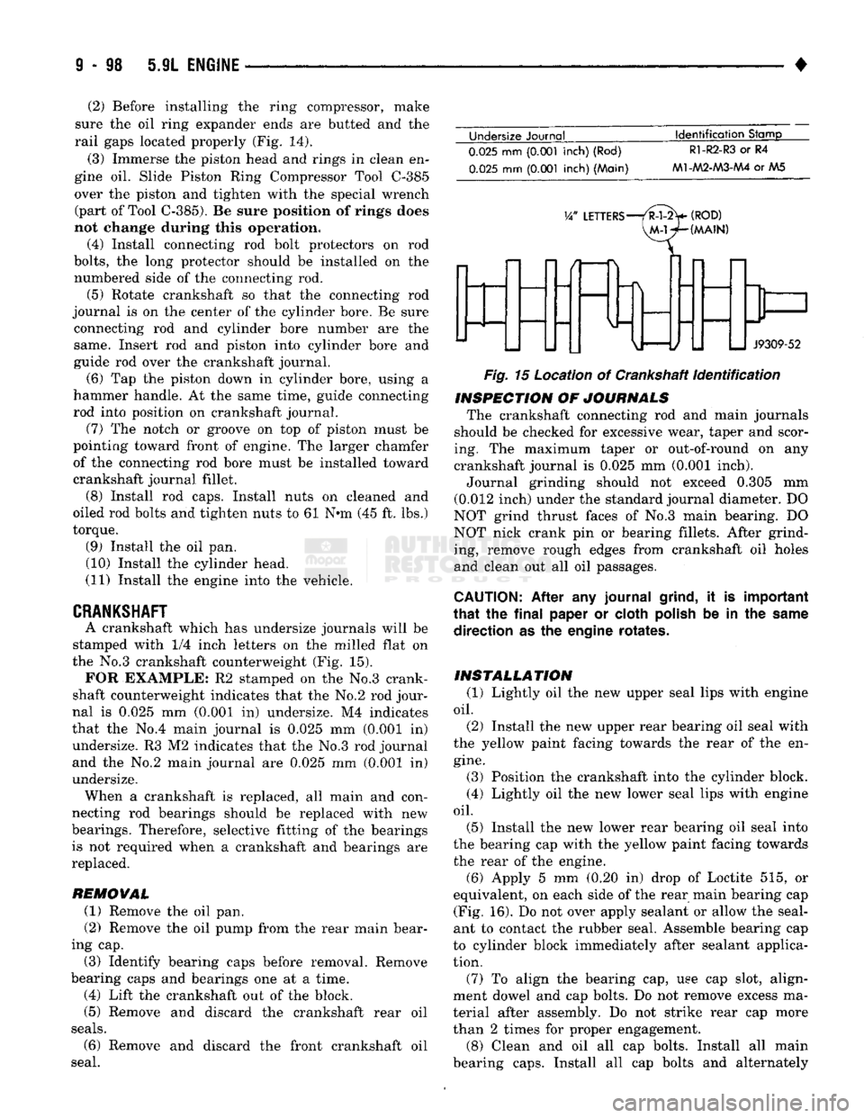
A crankshaft which has undersize journals will be
stamped with 1/4 inch letters on the milled flat on
the No.3 crankshaft counterweight (Fig. 15). FOR EXAMPLE: R2 stamped on the No.3 crank
shaft counterweight indicates that the No.2 rod jour
nal is 0.025 mm (0.001 in) undersize. M4 indicates
that the No.4 main journal is 0.025 mm (0.001 in) undersize. R3 M2 indicates that the No.3 rod journal
and the No.2 main journal are 0.025 mm (0.001 In)
undersize. When a crankshaft is replaced, all main and con
necting rod bearings should be replaced with new
bearings. Therefore, selective fitting of the bearings is not required when a crankshaft and bearings are
replaced.
REMOVAL
(1) Remove the oil pan.
(2) Remove the oil pump from the rear main bear
ing cap.
(3) Identify bearing caps before removal. Remove
bearing caps and bearings one at a time. (4) Lift the crankshaft out of the block.
(5) Remove and discard the crankshaft rear oil
seals.
(6) Remove and discard the front crankshaft oil
seal. Undersize Journal
Identification
Stamp
0.025
mm
(0.001
inch) (Rod)
0.025
mm
(0.001
inch) (Main)
R1-R2-R3
or R4
M1-AA2-M3-AA4
or AA5
V/
LETTERS—/R-l-2>
(ROD)
VM-WHMAIN)
J9309-52
Fig.
15 Location of Crankshaft
identification
INSPECTION
OF
JOURNALS
The crankshaft connecting rod and main journals
should be checked for excessive wear, taper and scor
ing. The maximum taper or out-of-round on any
crankshaft journal is 0.025 mm (0.001 inch).
Journal grinding should not exceed 0.305 mm
(0.012 inch) under the standard journal diameter. DO
NOT grind thrust faces of No.3 main bearing. DO
NOT nick crank pin or bearing fillets. After grind ing, remove rough edges from crankshaft oil holes
and clean out all oil passages.
CAUTION:
After any journal
grind,
it is important
that
the
final
paper or cloth
polish
be in the
same
direction as the engine rotates.
INSTALLATION
(1) Lightly oil the new upper seal lips with engine
oil.
(2) Install the new upper rear bearing oil seal with
the yellow paint facing towards the rear of the en
gine.
(3) Position the crankshaft into the cylinder block.
(4) Lightly oil the new lower seal lips with engine
oil.
(5) Install the new lower rear bearing oil seal into
the bearing cap with the yellow paint facing towards the rear of the engine. (6) Apply 5 mm (0.20 in) drop of Loctite 515, or
equivalent, on each side of the rear main bearing cap (Fig. 16). Do not over apply sealant or allow the seal
ant to contact the rubber seal. Assemble bearing cap
to cylinder block immediately after sealant applica
tion.
(7) To align the bearing cap, use cap slot, align
ment dowel and cap bolts. Do not remove excess ma
terial after assembly. Do not strike rear cap more
than 2 times for proper engagement.
(8) Clean and oil all cap bolts. Install all main
bearing caps. Install all cap bolts and alternately
Page 704 of 1502
•
5.9L ENGINE
9 - 99
BEARING
CAP
J9309-72
Fig.
16 Sealant Application to Bearing Cap tighten to 115 N-m (85 ft. lbs.) torque.
(9) Install oil pump.
(10) Apply Mopar Silicone Rubber Adhesive Seal
ant, or equivalent, at bearing cap to block joint to
provide cap to block and oil pan sealing (Fig. 17). Ap
ply enough sealant until a small amount is squeezed out. Withdraw nozzle and wipe excess sealant off the
oil pan seal groove. (11) Install new front crankshaft oil seal. (12) Immediately install the oil pan.
MOPAR SILICONE SEALANT
RUBBER
ADHESIVE APPLIED
Fig.
17
Apply
Sealant to Bearing Cap to
Block
Joint
CRANKSHAFT
MAIN BEARINGS
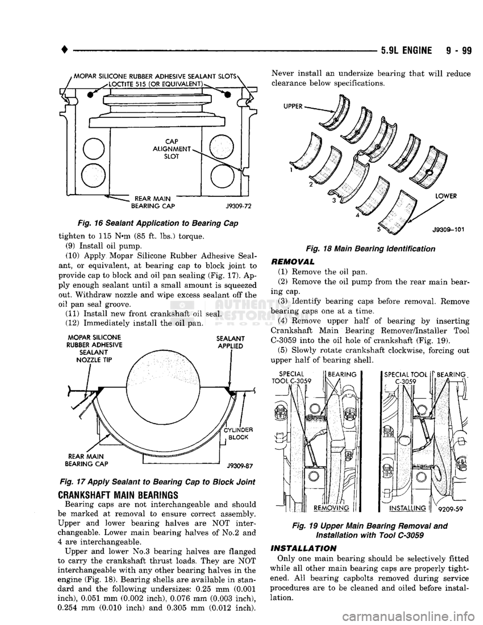
Bearing caps are not interchangeable and should
be marked at removal to ensure correct assembly. Upper and lower bearing halves are NOT inter
changeable. Lower main bearing halves of No.2 and
4 are interchangeable. Upper and lower No.3 bearing halves are flanged
to carry the crankshaft thrust loads. They are NOT interchangeable with any other bearing halves in the
engine (Fig. 18). Bearing shells are available in stan
dard and the following undersizes: 0.25 mm (0.001
inch),
0.051 mm (0.002 inch), 0.076 mm (0.003 inch), 0.254 mm (0.010 inch) and 0.305 mm (0.012 inch). Never install an undersize bearing that will reduce
clearance below specifications.
Fig.
18 Main Bearing
Identification
REMOVAL (1) Remove the oil pan.
(2) Remove the oil pump from the rear main bear
ing cap. (3) Identify bearing caps before removal. Remove
bearing caps one at a time.
(4) Remove upper half of bearing by inserting
Crankshaft Main Bearing Remover/Installer Tool
C-3059 into the oil hole of crankshaft (Fig. 19).
(5) Slowly rotate crankshaft clockwise, forcing out
upper half of bearing shell.
Fig.
19 Upper Main Bearing
Removal
and
Installation
with
Tool C-3059
INSTALLATION
Only one main bearing should be selectively fitted
while all other main bearing caps are properly tight ened. All bearing capbolts removed during service
procedures are to be cleaned and oiled before instal lation.