1993 DODGE TRUCK torque
[x] Cancel search: torquePage 1409 of 1502
23
- 26
BODY COMPONENTS
• (2) Install the spacer and replacement striker on
the B-pillar.
(3) Adjust the door latch striker to engage com
pletely when the door is closed. When closed, the
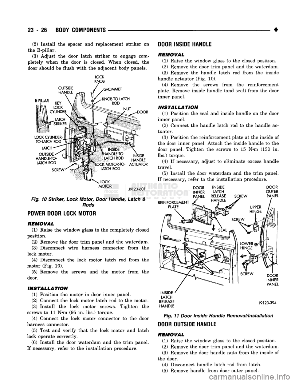
door should be flush with the adjacent body panels. IOCK
KNOB
OUTSIDE HANDLE GROMMET
B-PILLAR DOOR
LATCH
OUTSIDE
HANDLE-TO- LATCH ROD
SCREW INSIDE
HANDLE
LOCK MOTOR-TO- ACTUATOR LATCH ROD
LOCK
MOTOR
J9123-601
Fig.
10
Striker,
Lock
Motor,
Door
Handle, Latch &
Rods
POWER
DOOR LOCK MOTOR
REMOVAL
(1) Raise the window glass to the completely closed
position.
(2) Remove the door trim panel and the waterdam.
(3) Disconnect wire harness connector from the
lock motor.
(4) Disconnect the lock motor latch rod from the
motor (Fig. 10).
(5) Remove the screws and the motor from the
door.
INSTALLATION
(1) Position the motor in door inner panel.
(2) Connect the lock motor latch rod to the motor.
(3) Install the lock motor screws. Tighten the
screws to 11 N#m (95 in. lbs.) torque. (4) Connect the lock motor connector to the door
harness connector.
(5) Test and verify that the lock motor and latch
lock operate correctly.
(6) Install the door waterdam and the trim panel.
If necessary, refer to the installation procedure. DOOR INSIDE HANDLE
REMOVAL
(1) Raise the window glass to the closed position.
(2) Remove the door trim panel and the waterdam.
(3) Remove the handle latch rod from the inside
handle actuator (Fig. 10).
(4) Remove the screws from the reinforcement
plate. Remove inside handle (and seal) from the door inner panel.
INSTALLATION
(1) Position the seal and inside handle on the door
inner panel.
(2) Connect the handle latch rod to the handle ac
tuator. (3) Position the reinforcement plate at the inside of
the door inner panel. Attach the inside handle to the door panel. Tighten the screws to 15 N#m (130 in.
lbs.) torque.
(4) If necessary, adjust to eliminate excess handle
travel.
(5) Install the door waterdam and the trim panel.
If necessary, refer to the installation procedure. DOOR
INNER PANEL
REINFORCEMENT PLATE INSIDE
LATCH
RELEASE HANDLE SCREW DOOR
OUTER PANEL
INSIDE LATCH
RELEASE HANDLE DOOR
INNER PANEL
J9123-394
Fig.
11
Door
Inside
Handle Removal/Installation DOOR OUTSIDE HANDLE
REMOVAL
(1) Raise the window glass to the closed position.
(2) Remove the door trim panel and the waterdam. (3) Remove the door handle nuts from the inside of
the door. (4) Disconnect handle latch rod from latch.
(5) Remove handle from door outer panel.
Page 1410 of 1502
•
BODY
COMPONENTS
23 - 27
INSTALLATION
(1)
Apply silicone spray lubricant to the handle in
ternal moving parts.
(2) Install the handle on the door outer panel.
(3) Tighten the handle nuts to 7 N*m (65 in. lbs.)
torque. (4) Connect the handle latch rod to the latch.
(5) Test and verify the handle operates correctly.
(6)
Install the door waterdam and the trim panel.
OUTSIDE HANDLE LATCH
ROD
RELEASE
ADJUSTMENT
(1) Locate the 4-mm (5/32-in) diameter Allen-head
adjustment screw inside the door panel face slot near
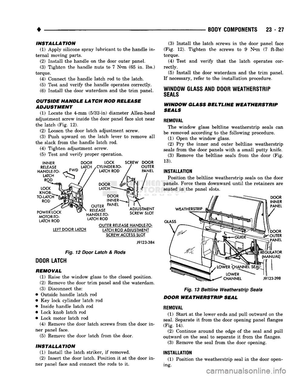
the latch (Fig. 12).
(2) Loosen the door latch adjustment screw.
(3) Push upward on the latch lever to remove all
the slack from the handle latch rod.
(4) Tighten adjustment screw.
(5) Test and verify proper operation.
INNER
RELEASE
HANDLE-TO
LATCH
ROD
LOCK
KNOB
TO-LATCH
ROD
POWER
LOCK
MOTOR-TO-LATCH
ROD
DOOR
LATCH
LOCK
/CYLINDER-TO LATCH
ROD
SCREW
DOOR
OUTER
PANEL
DOOR
LATCH
DOOR
INNER
OUTER
PANEL
RELEASE
HANDLE-TO LATCH
ROD
ADJUSTMENT
SCREW
SLOT
LEFT
DOOR LATCH OUTER
RELEASE
HANDLE-TO-
LATCH ROD ADJUSTMENT
SCREW
ACCESS
SLOT
J9123-384
Fig.
12
Door
Latch &
Rods
DOOR
LATCH
REMOVAL
(1) Raise the window glass to the closed position.
(2) Remove the door trim panel and the waterdam.
(3) Disconnect the:
• Outside handle latch rod
• Key lock cylinder latch rod
• Inside handle latch rod
• Lock knob latch rod
• Lock motor latch rod (4) Remove the door latch screws from the door in
ner panel face.
(5) Remove the door latch from the door.
INSTALLATION
(1) Install the latch striker, if removed.
(2) Insert the door latch. Position it at the door in
ner panel face and connect the rods to it. (3) Install the latch screws in the door panel face
(Fig. 12). Tighten the screws to 9 Nnn (7 ft-lbs)
torque.
(4) Test and verify that the latch operates cor
rectly. (5) Install the door waterdam and the trim panel.
If necessary, refer to the installation procedure.
WINDOW
GLASS
AND
DOOR
WEATHERSTRIP
SEALS
WINDOW
GLASS
BELTLINE WEATHERSTRIP
SEALS
REMOVAL
The window glass beltline weatherstrip seals can
be removed according to the following procedure. (1) Open the window glass.
(2) Pry the inner and outer beltline weatherstrip
seals from the door panels with a small putty knife.
(3) Remove the beltline seals from the door (Fig.
13).
INSTALLATION
Position the beltline weatherstrip seals on the door
panels. Force them downward until the retainers are seated in the panel slots.
WEATHERSTRIP
GLASS
DOOR
INNER
PANEL
DOOR
OUTER
PANEL
REGULATOR
(MANUAL)
J9123-398
Fig. 13 Beltline Weatherstrip Seals
DOOR
WEATHERSTRIP
SEAL
REMOVAL
(1) Start at the lower ends and pull outward on the
seal. Separate it from the door opening panel flanges
(Fig. 14). (2) Continue around the edge of the seal and pull
outward on the seal to separate it from the flanges.
(3) Remove the seal from the door opening.
INSTALLATION
(1) Position the weatherstrip seal in the door open
ing.
Page 1413 of 1502
23
- 30
BODY COMPONENTS
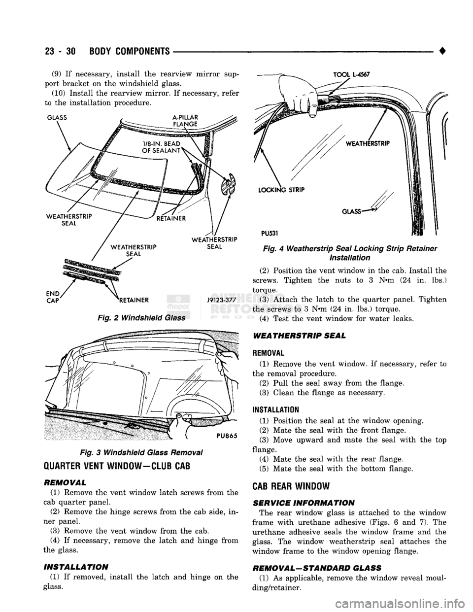
• (9) If necessary, install the rearview mirror sup
port bracket on the windshield glass. (10) Install the rearview mirror. If necessary, refer
to the installation procedure.
Fig.
2 Windshield
Glass
Fig.
3 Windshield
Glass
Removal
QUARTER WENT WINDOW-CLUB CAB
REMOVAL
(1) Remove the vent window latch screws from the
cab quarter panel.
(2) Remove the hinge screws from the cab side, in
ner panel.
(3) Remove the vent window from the cab.
(4) If necessary, remove the latch and hinge from
the glass.
INSTALLATION
(1) If removed, install the latch and hinge on the
glass.
Fig.
4
Weatherstrip
Seal Locking
Strip Retainer
Installation
(2) Position the vent window in the cab. Install the
screws. Tighten the nuts to 3 N#m (24 in. lbs.)
torque. (3) Attach the latch to the quarter panel. Tighten
the screws to 3 N«m (24 in. lbs.) torque. (4) Test the vent window for water leaks.
WEATHERSTRIP
SEAL
REMOVAL
(1) Remove the vent window. If necessary, refer to
the removal procedure. (2) Pull the seal away from the flange. (3) Clean the flange as necessary.
INSTALLATION
(1) Position the seal at the window opening.
(2) Mate the seal with the front flange.
(3) Move upward and mate the seal with the top
flange. (4) Mate the seal with the rear flange.
(5) Mate the seal with the bottom flange.
CAB REAR WINDOW
SERVICE
INFORMATION
The rear window glass is attached to the window
frame with urethane adhesive (Figs. 6 and 7). The
urethane adhesive seals the window frame and the
glass.
The window weatherstrip seal attaches the
window frame to the window opening flange.
REMOVAL-STANDARD
GLASS
(1) As applicable, remove the window reveal moul
ding/retainer.
Page 1418 of 1502
•
BODY
COMPONENTS
23 - 35
CAB/BODY
INTERIOR COMPONENTS
INDEX
page
Carpets
and
Floor Mats
51
Floor Console
and
Rear Storage Tray
.........
50
Front Seats
38
Headliners
48
Instrument
Panel
35
page
Interior
Trim
Panels
. 42
Rear
Seats
41
Shoulder
Belts/Lap Belt/Buckles
45
Spare
Tire
Carrier
45
INSTRUMENT
PANEL INSTRUMENT CLUSTER BEZEL
REMOVAL
(1) Remove
the
bezel screws.
(2) Remove
the
bezel from
the
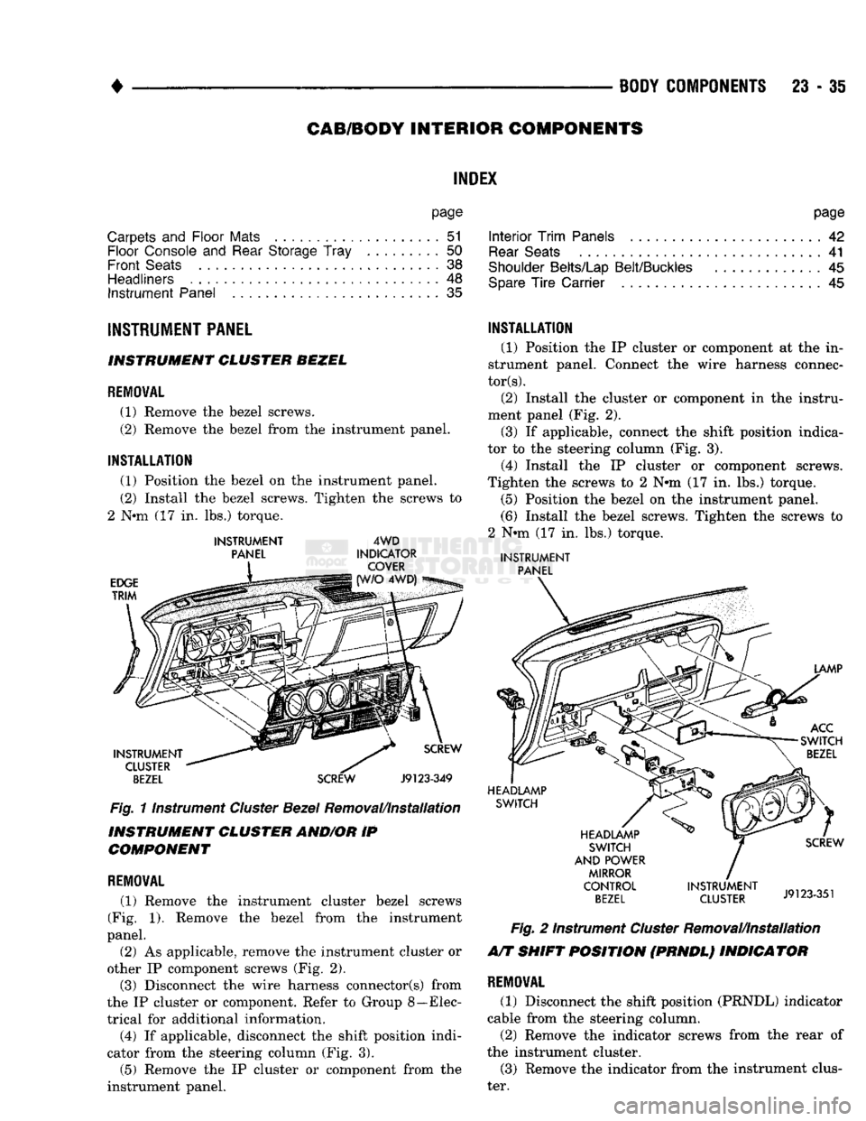
instrument panel.
INSTALLATION
(1) Position
the
bezel
on the
instrument panel.
(2) Install
the
bezel screws. Tighten
the
screws
to
2
Nnn (17 in. lbs.)
torque.
INSTRUMENT
PANEL
EDGE
TRIM
4WD
INDICATOR COVER 4WD)
INSTRUMENT CLUSTER
BEZEL
SCREW
Fig.
11nstrument
Cluster
Bezel
Removal/Installation
INSTRUMENT CLUSTER AND/OR
IP
COMPONENT
REMOVAL
(1) Remove
the
instrument cluster bezel screws
(Fig.
1).
Remove
the
bezel from
the
instrument
panel.
(2)
As
applicable, remove
the
instrument cluster
or
other
IP
component screws
(Fig. 2).
(3) Disconnect
the
wire harness connector(s) from
the
IP
cluster
or
component. Refer
to
Group 8—Elec
trical
for
additional information. (4)
If
applicable, disconnect
the
shift position indi
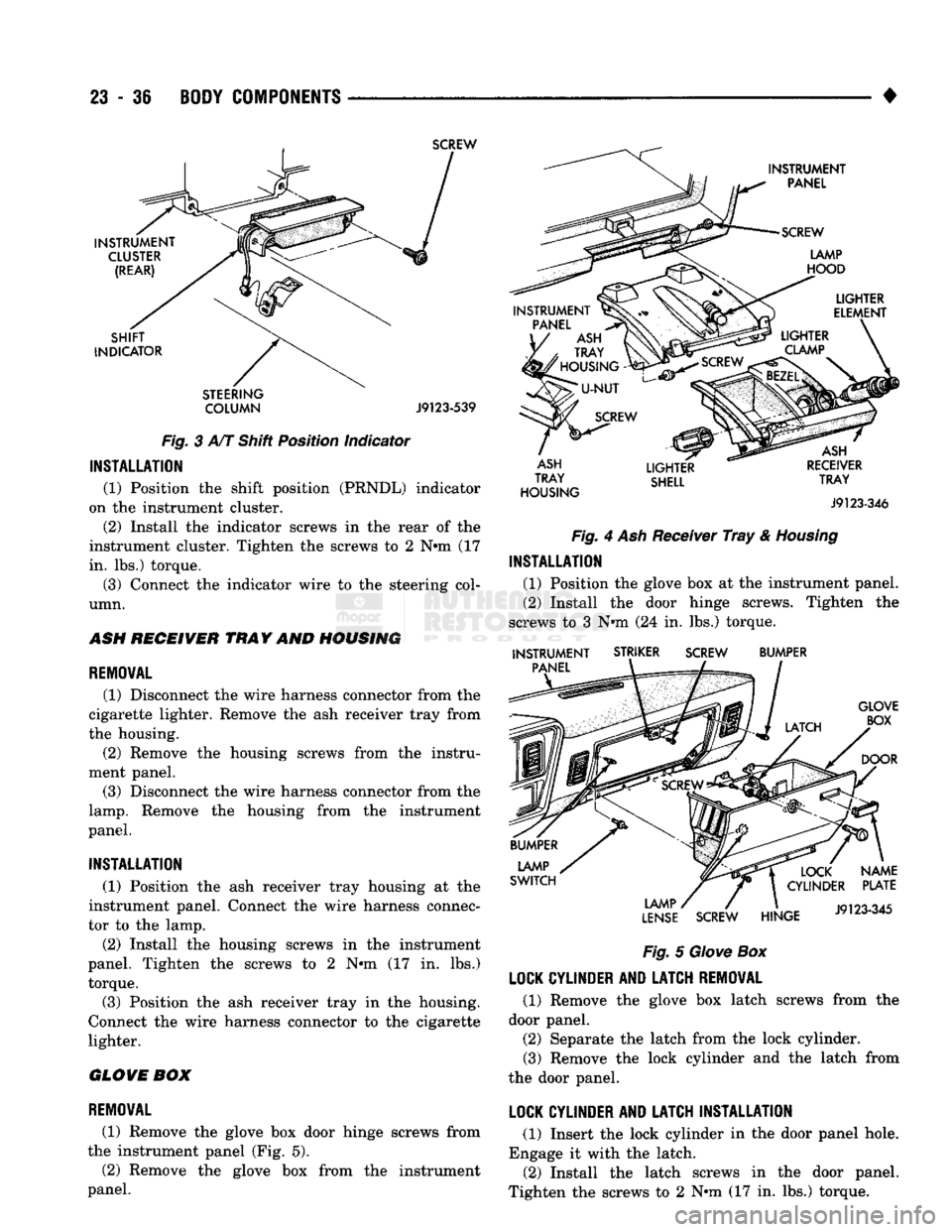
cator from
the
steering column
(Fig. 3).
(5) Remove
the IP
cluster
or
component from
the
instrument panel.
INSTALLATION
(1) Position
the IP
cluster
or
component
at the in
strument panel. Connect
the
wire harness connec
tors).
(2) Install
the
cluster
or
component
in the
instru
ment panel
(Fig. 2).
(3)
If
applicable, connect
the
shift position indica
tor
to the
steering column
(Fig. 3).
(4) Install
the IP
cluster
or
component screws.
Tighten
the
screws
to 2 N#m (17 in. lbs.)
torque. (5) Position
the
bezel
on the
instrument panel.
(6) Install
the
bezel screws. Tighten
the
screws
to
2
Nnn (17 in. lbs.)
torque.
INSTRUMENT
PANEL
LAMP
ACC
SWITCH
BEZEL
HEADLAMP SWITCH
HEADLAMP SWITCH
AND POWER MIRROR
CONTROL
BEZEL
SCREW
INSTRUMENT
J9123351
CLUSTER
J9123-351
Fig.
2
Instrument
Cluster
Removal/Installation
A/T SHIFT POSITION (PRNDL) INDICATOR
REMOVAL
(1) Disconnect
the
shift position (PRNDL) indicator
cable from
the
steering column.
(2) Remove
the
indicator screws from
the
rear
of
the instrument cluster. (3) Remove
the
indicator from
the
instrument clus
ter.
Page 1419 of 1502
23
- 36
BODY COMPONENTS
SCREW
INSTRUMENT
CLUSTER (REAR)
SHIFT
INDICATOR
STEERING COLUMN
J9123-539
Fig.
3 A/T Shift Position Indicator
INSTALLATION
(1) Position the shift position (PRNDL) indicator
on the instrument cluster.
(2) Install the indicator screws in the rear of the
instrument cluster. Tighten the screws to 2 N»m (17
in. lbs.) torque.
(3) Connect the indicator wire to the steering col
umn.
ASH
RECEIVER
TRAY
AND
HOUSING
REMOVAL
(1) Disconnect the wire harness connector from the
cigarette lighter. Remove the ash receiver tray from
the housing. (2) Remove the housing screws from the instru
ment panel. (3) Disconnect the wire harness connector from the
lamp.
Remove the housing from the instrument
panel.
INSTALLATION
(1) Position the ash receiver tray housing at the
instrument panel. Connect the wire harness connec
tor to the lamp.
(2) Install the housing screws in the instrument
panel. Tighten the screws to 2 N«m (17 in. lbs.)
torque. (3) Position the ash receiver tray in the housing.
Connect the wire harness connector to the cigarette
lighter.
GLOVE
BOX
REMOVAL
(1) Remove the glove box door hinge screws from
the instrument panel (Fig. 5).
(2) Remove the glove box from the instrument
panel.
INSTRUMENT
PANEL
SCREW
LAMP
HOOD
PANEL
ASH
TRAY
'
HOUSING
-
LIGHTER
ELEMENT
SCREW
LIGHTER
CLAMP
ASH
TRAY
HOUSING
LIGHTER
SHELL
ASH
RECEIVER
TRAY
J9123-346
Fig.
4 Ash Receiver
Tray
&
Housing
INSTALLATION
(1) Position the glove box at the instrument panel.
(2) Install the door hinge screws. Tighten the
screws to 3 N»m (24 in. lbs.) torque.
INSTRUMENT
PANEL
STRIKER
SCREW
BUMPER
GLOVE BOX
DOOR
LAMP
SWITCH
LAMP
LENSE
SCREW
HINGE
NAME
PLATE
J9123-345
Fig.
5
Glove
Box
LOCK
CYLINDER
AND
LATCH
REMOVAL
(1) Remove the glove box latch screws from the
door panel. (2) Separate the latch from the lock cylinder.
(3) Remove the lock cylinder and the latch from
the door panel.
LOCK
CYLINDER
AND
LATCH
INSTALLATION
(1) Insert the lock cylinder in the door panel hole.
Engage it with the latch. (2) Install the latch screws in the door panel.
Tighten the screws to 2 N»m (17 in. lbs.) torque.
Page 1420 of 1502
BODY
COMPONENTS
23 - 37
DOOR
LATCH STRIKER ADJUSTMENT
(1) Insert a small pry bar in the latch striker slot.
(2) Pry on the striker as necessary to obtain cor
rect adjustment.
INSTRUMENT PANEL
(UP)
REMOVAL
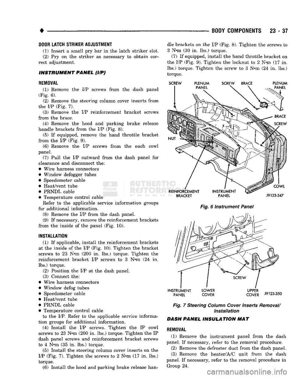
(1) Remove the I/P screws from the dash panel
(Fig. 6). (2) Remove the steering column cover inserts from
the I/P (Fig. 7). (3) Remove the I/P reinforcement bracket screws
from the brace. (4) Remove the hood and parking brake release
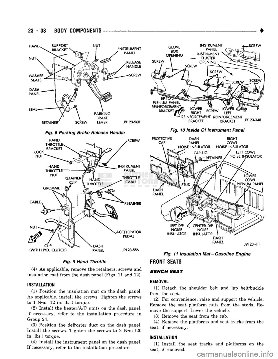
handle brackets from the I/P (Fig. 8).
(5) If equipped, remove the hand throttle bracket
from the I/P (Fig. 9).
(6) Remove the I/P screws from the each cowl
panel.
(7) Pull the I/P outward from the dash panel for
clearance and disconnect the:
• Wire harness connectors
• Window defogger tubes
• Speedometer cable
• Heat/vent tube
• PRNDL cable
• Temperature control cable Refer to the applicable service information groups
for additional information.
(8) Remove the I/P from the dash panel.
(9) If necessary, remove the reinforcement brackets
from the inside of the panel (Fig. 10).
INSTALLATION
(1) If applicable, install the reinforcement brackets
at the inside of the I/P (Fig. 10). Tighten the bracket
screws to 23 N#m (200 in. lbs.) torque. Tighten the
reinforcement bracket I/P screws to 3 N*m (24 in. lbs.) torque.
(2) Position the I/P at the dash panel. (3) Connect the:
• Wire harness connectors
• Window defog tubes
• Speedometer cable
• Heat/vent tube
• PRNDL cable
• Temperature control cable
to the I/P. Refer to the applicable service informa
tion groups for additional information. (4) Install the I/P screws. Tighten the IP cowl
screws to 23 N-m (200 in. lbs.) torque. Tighten the IP
dash panel screws and reinforcement bracket screws
to 4 N»m (35 in. lbs.) torque.
(5) Install the steering column cover inserts on the
17P (Fig. 7). Tighten the screws to 2 N*m (17 in. lbs.)
torque.
(6) Install the hood and parking brake release han dle brackets on the I/P (Fig. 8). Tighten the screws to
3 N*m (30 in. lbs.) torque. (7) If equipped, install the hand throttle bracket on
the I/P (Fig. 9). Tighten the locknut to 2 N*m (17 in. lbs.) torque. Tighten the screw to 3 N*m (24 in. lbs.)
torque.
SCREW
PLENUM SCREW BRACE PLENUM
Fig.
6 Instrument
Panel
INSTRUMENT LOWER UPPER
irt
PANEL COVER COVER
J9123-350
Fig.
7 Steering
Column
Cover
Inserts
Removal/
Installation
DASH
PANEL INSULATION
MAT
REMOVAL
(1) Remove the instrument panel from the dash
panel. If necessary, refer to the removal procedure. (2) Remove the defroster duct from the dash panel. (3) Remove the heater/A/C unit from the dash
panel. If necessary, refer to the removal procedure in Group 24.
Page 1421 of 1502
23 - 38
BODY COMPONENTS
— —
^—_____— —
•
PAWU
NUT
WASHER
SEALS
DASH
PANEL
SEAL
SUPPORT
BRACKET
NUT
INSTRUMENT
PANEL
RELEASE
HANDLE SCREW
RETAINER'
PARKING
BRAKE
SCREW LEVER J9123-568
Fig.
8 Parking Brake
Release
Handle
LOCK
NUT
HAND
THROTTLE BRACKET SCREW
INSTRUMENT PANEL
HAND
^TfJlLE
>TTLE
RETAINER
CLIP
(WITH
HYD.
CLUTCH)
DASH
PANEL ACCELERATOR
PEDAL
J9123-556
Fig.
9
Hand
Throttle
(4) As applicable, remove the retainers, screws and
insulation mat from the dash panel (Figs. 11 and 12).
INSTALLATION
(1) Position the insulation mat on the dash panel.
As applicable, install the screws. Tighten the screws
to 1 N«m (12 in. lbs.) torque.
(2) Install the heater/A/C units on the dash panel.
If necessary, refer to the installation procedure in Group 24.
(3) Position the defroster duct on the dash panel.
Install the screws. Tighten the screws to 2 N*m (20
in. lbs.) torque.
(4) Install the instrument panel on the dash panel.
If necessary, refer to the installation procedure.
GLOVE
BOX
OPENING
SCREW INSTRUMENT
PANEL
INSTRUMENT
-
CLUSTER
OPENING
l/P-T
PLENUM
PANEL
REINFORCEMENT;
BRACKET
7
LOWER
RIGHT
SCREW
REINFORCEMENT REINFORCEMENT
BRACKET BRACKET J9123-348
Fig.
10
Inside
Of Instrument
Panel
PROTECTIVE
CAP DASH
PANEL
NOISE
INSULATOR
RIGHT
COWL
NOISE
INSULATOR
LEFT
COWL
NOISE
INSULATOR
LEFT
DIP
NOISE
INSULATOR
CENTER
DIP
NOISE
INSULATOR DASH
PANEL
J9123-411
Fig.
11 Insulation Mat—Gasoline
Engine
FRONT
SEATS BENCH SEAT
REMOVAL
(1) Detach the shoulder belt and lap belt/buckle
from the seat.
(2) For convenience, raise and support the vehicle.
Remove the seat platform nuts from the studs. Re
move the support. Lower the vehicle.
(3) Remove the seat from the cab.
(4) Remove the platforms and seat tracks from the
seat, if necessary.
INSTALLATION
(1) Install the seat tracks and platforms on the
seat, if removed.
Page 1422 of 1502
•
BODY
COMPONENTS
23 - 39
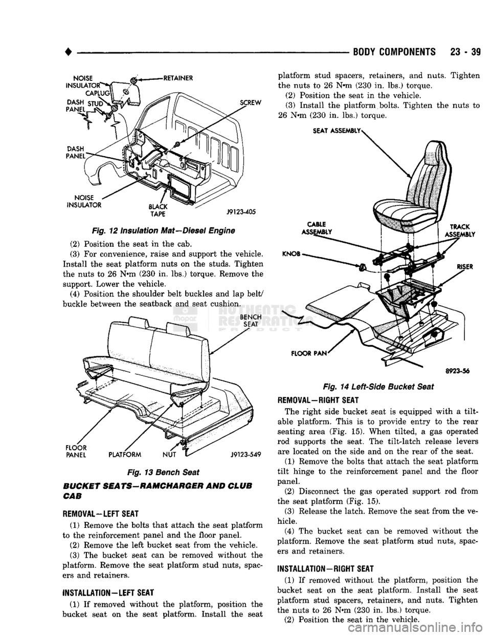
Fig.
12 Insulation Mat—Diesel
Engine
(2) Position the seat in the cab.
(3) For convenience, raise and support the vehicle.
Install the seat platform nuts on the studs. Tighten
the nuts to 26 Nnn (230 in. lbs.) torque. Remove the support. Lower the vehicle.
(4) Position the shoulder belt buckles and lap belt/
buckle between the seatback and seat cushion.
Fig.
13
Bench
Seat
BUCKET SEATS-RAMCHARGER AND CLUB CAB
REMOVAL—LEFT SEAT
(1) Remove the bolts that attach the seat platform
to the reinforcement panel and the floor panel.
(2) Remove the left bucket seat from the vehicle.
(3) The bucket seat can be removed without the
platform. Remove the seat platform stud nuts, spac ers and retainers. platform stud spacers, retainers, and nuts. Tighten
the nuts to 26 Nnn (230 in. lbs.) torque.
(2) Position the seat in the vehicle. (3) Install the platform bolts. Tighten the nuts to
26 Nnn (230 in. lbs.) torque.
8923-56
Fig.
14
Left-Side
Bucket Seat
REMOVAL—RIGHT SEAT
The right side bucket seat is equipped with a tilt-
able platform. This is to provide entry to the rear
seating area (Fig. 15). When tilted, a gas operated
rod supports the seat. The tilt-latch release levers are located on the side and on the rear of the seat.
(1) Remove the bolts that attach the seat platform
tilt hinge to the reinforcement panel and the floor
panel.
(2) Disconnect the gas operated support rod from
the seat platform (Fig. 15).
(3) Release the latch. Remove the seat from the ve
hicle.
(4) The bucket seat can be removed without the
platform. Remove the seat platform stud nuts, spac ers and retainers.
INSTALLATION-RIGHT
SEAT
(1) If removed without the platform, position the
bucket seat on the seat platform. Install the seat
platform stud spacers, retainers, and nuts. Tighten
the nuts to 26 Nnn (230 in. lbs.) torque.
(2) Position the seat in the vehicle.
INSTALLATION—LEFT
SEAT
(1) If removed without the platform, position the
bucket seat on the seat platform. Install the seat