1993 DODGE TRUCK torque
[x] Cancel search: torquePage 1464 of 1502
•
HEATING
AND AIR
CONDITIONING
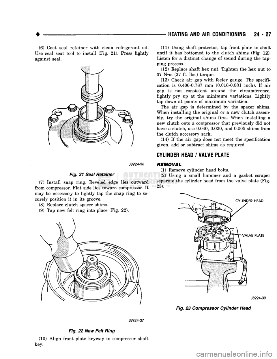
24 - 27 (6) Coat seal retainer with clean refrigerant oil.
Use seal seat tool to install (Fig. 21). Press lightly against seal.
J8924-36
Fig.
21
Seal
Retainer
(7) Install snap ring. Beveled edge lies outward
from compressor. Flat side lies toward compressor. It
may be necessary to lightly tap the snap ring to se curely position it in its groove.
(8) Replace clutch spacer shims.
(9) Tap new felt ring into place (Fig. 22).
J8924-37
Fig.
22 New
Felt
Ring
(10) Align front plate keyway to compressor shaft
key. (11) Using shaft protector, tap front plate to shaft
until it has bottomed to the clutch shims (Fig. 12).
Listen for a distinct change of sound during the tap
ping process.
(12) Replace shaft hex nut. Tighten the hex nut to
37 N-m (27 ft. lbs.) torque.
(13) Check air gap with feeler gauge. The specifi
cation is 0.406-0.787 mm (0.016-0.031 inch). If air
gap is not consistent around the circumference,
lightly pry up at the minimum variations. Lightly
tap down at points of maximum variation.
The air gap is determined by the spacer shims.
When installing the original or a new clutch assem
bly, try the original shims first. When installing a new clutch onto a compressor that previously did not
have a clutch, use 0.040, 0.020, and 0.005 shims from
the clutch accessory sack.
(14) If the air gap does not meet the specification
given, add or subtract shims as required.
CYLINDER
HEAD
/
VALVE PLATE
REMOVAL
(1) Remove cylinder head bolts.
(2) Using a small hammer and a gasket scraper
separate the cylinder head from the valve plate (Fig.
23).
J8924-39
Fig.
23
Compressor
Cylinder Head
Page 1465 of 1502
24
- 28
HEATING
AND AIR
CONDITIONING
—
J8924-40
Fig.
24
Waive
Plate
(5) Visually inspect the rear valves and discharge
retainer for damage. Discard any component if any
portion is damaged.
If valve plate and/or cylinder head are to be reused,
carefully remove gasket materials using the gasket scraper. Do not damage cylinder block or valve plate
surfaces. . . . _ #
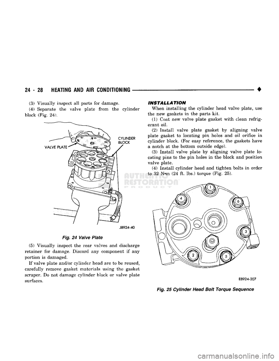
E8924-207
Fig.
25 Cylinder Head
Bolt
Torque
Sequence
INSTALLATION
When installing the cylinder head valve plate, use
the new gaskets in the parts kit. (1) Coat new valve plate gasket with clean refrig
erant oil. (2) Install valve plate gasket by aligning valve
plate gasket to locating pin holes and oil orifice in cylinder block. (For easy reference, the gaskets have a notch at the bottom outside edge). (3) Install valve plate by aligning valve plate lo
cating pins to the pin holes in the block and position
valve plate. (4) Install cylinder head and tighten bolts in order
to 32 N*m (24 ft. lbs.) torque (Fig. 25).
(3) Visually inspect all parts for damage.
(4) Separate the valve plate from the cylinder
block (Fig. 24).
Page 1474 of 1502
•
Fig.
12
Blower
Wheel
(7) Install the 3 arms. Install nut that attaches 3
door arms to doors on the top cover of the unit (Fig.
11).
INSTALLATION
(1) Install the evaporator heater assembly. Plastic
instrument panel may have to be flexed outward.
(2) Install and tighten the screw that retains the
evaporator heater assembly to cowl side sheet metal.
(3) Install the retaining nuts on engine side.
(4) Connect vacuum lines on engine side.
(5) Install blower motor connector on engine side.
(6) Remove wiring connector from resistor block.
(7) Connect vacuum lines from extension on con
trol unit and attach vacuum lines to defroster duct (Fig. 10).
(8) Connect temperature control cable to unit
through glove box. (9) Install floor air distribution duct.
(10) Install center distribution duct.
(11) Attach radio ground strap. (12) Remove right half of lower reinforcement by
removing screws attaching it to the instrument panel and the screw attaching it to the cowl side trim
panel. (13) Install ash receiver.
(14) Install structural brace through glove box
opening. Install screws and loosen nuts. (15) Install glove box by installing mounting
screws. (16) Install right cowl side trim panel, if so
equipped. (17) Position transfer case and/or gear shift levers.
(18) Remove plugs from heater hoses and unit. In
stall condensate tube (Fig. 9). (19) Connect refrigerant and heater lines to unit
on engine side.
} (20) Connect the negative cable to the battery. (21) Fill the cooling system (refer to Group 7, Cool
ing System). (22) Evacuate and charge the system.
(23) Check operation of all controls and perfor
mance of the A/C system.
HEATING
AND AIR
CONDITIONING
24 - 37
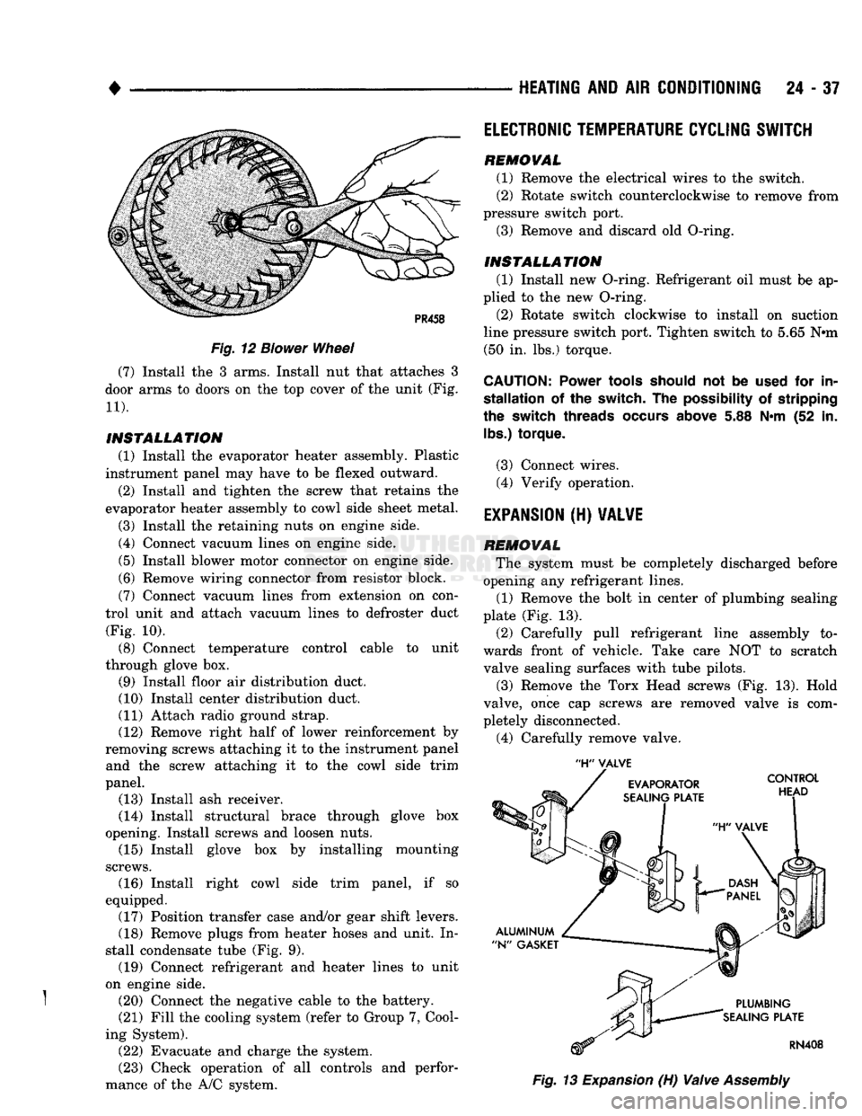
'H"
VALVE
Fig.
13
Expansion
(H)
Valve
Assembly
ELECTRONIC
TEMPERATURE
CYCLING
SWITCH
REMOVAL
(1) Remove the electrical wires to the switch.
(2) Rotate switch counterclockwise to remove from
pressure switch port. (3) Remove and discard old O-ring.
INSTALLATION
(1) Install new O-ring. Refrigerant oil must be ap
plied to the new O-ring.
(2) Rotate switch clockwise to install on suction
line pressure switch port. Tighten switch to 5.65 N#m (50 in. lbs.) torque.
CAUTION:
Power
tools
should
not be
used
for in
stallation
of the switch. The
possibility
of stripping
the
switch
threads
occurs
above
5.88 N*m (52 in.
lbs.)
torque.
(3) Connect wires. (4) Verify operation.
EXPANSION
(H)
VALVE
REMOVAL
The system must be completely discharged before
opening any refrigerant lines. (1) Remove the bolt in center of plumbing sealing
plate (Fig. 13).
(2) Carefully pull refrigerant line assembly to
wards front of vehicle. Take care NOT to scratch valve sealing surfaces with tube pilots.
(3) Remove the Torx Head screws (Fig. 13). Hold
valve, once cap screws are removed valve is com
pletely disconnected.
(4) Carefully remove valve.
Page 1475 of 1502
24
- 38
HEATING
AND AIR
CONDITIONING
INSTALLATION
(1) Remove and replace the aluminum N-gaskets
(1 on evaporator plate and 1 on plumbing plate). (2) Remove sealing cap from H-valve control head
side sealing surface and hold it against evaporator
sealing plate. DO NOT scratch sealing surface. In
stall the Torx Drive screws and tighten to 11 N-m (100 in. lbs.) torque.
(3) Remove sealing cap from plumbing side sealing
surface and hold plumbing up to valve. Install the
bolt and tighten to 23 N*m (200 in. lbs.) torque.
(4) Connect wires to electronic temperature cycling
switch. (5) After expansion valve is installed and system
charged and leak checked, repeat performance check.
AIR CONDITIONER DISTRIBUTION AND SPOT
COOLER
DUCTS-CENTER
REMOVAL (1) Disconnect the negative cable from the battery.
(2) Open glove box past stops.
(3) Remove right upper air duct by removing
mounting screw and pulling duct out through glove
box opening (Fig. 9).
(4) Remove instrument panel center brace.
(5) Remove right kick pad.
(6) Remove right instrument panel pivot bolt.
(7) Remove instrument panel cluster.
(8) Disconnect shift indicator cable.
(9) Lower steering column.
(10) Remove steering column studs.
(11) Remove radio.
(12) Remove mounting screws and remove scoop
connecting heater unit to center distribution duct. (13) Remove mounting screws and remove center
distribution duct by pulling bottom of instrument
panel out and dropping duct out (Fig. 9).
INSTALLATION
(1) Position the center distribution duct through
the bottom of instrument panel (Fig. 9). Install mounting screws.
(2) Position the scoop connecting heater unit to
center distribution duct. Install mounting screws.
(3) Install radio.
(4) Install steering column studs.
(5) Place steering column into position.
(6) Connect shift indicator cable.
(7) Install instrument panel cluster.
(8) Install right instrument panel pivot bolt.
(9) Install right kick pad.
(10) Install instrument panel center brace.
(11) Position the duct in through glove box open
ing (Fig. 9). Install mounting screw. (12) Close glove box.
(13) Connect the negative cable to the battery.
AIR CONDITIONER DISTRIBUTION AND SPOT
COOLER
DUCTS-RIGHT BI-LEVEL
REMOVAL (1) Disconnect the negative cable from the battery. (2) Open glove box past stops.
(3) Remove right upper air duct by removing
mounting screw and pulling duct out through glove
box opening (Fig. 9).
INSTALLATION
(1) Position the right upper air duct through glove
box opening (Fig. 9). Install mounting screw.
(2) Close glove box.
(3) Connect the negative cable to the battery.
AIR CONDITIONER DISTRIBUTION AND SPOT
COOLER
DUCTS-LEFT BI-LEVEL
REMOVAL
(1) Disconnect the negative cable from the battery.
(2) Remove instrument panel cluster.
(3) Disconnect shift indicator cable.
(4) Remove heater control.
(5) Remove mounting screws and cover that re
tains instrument panel wiring and let wiring hang
free.
(6) Remove mounting screw and slide left air duct
out through instrument cluster opening (Fig. 9).
INSTALLATION
(1) Slide left air duct in through instrument clus
ter opening (Fig. 9). Install mounting screw. (2) Position the cover that retains instrument
panel wiring. Install mounting screws.
(3) Install heater control.
(4) Connect shift indicator cable.
(5) Install instrument panel cluster.
(6) Connect the negative cable to the battery.
AIR OUTLET
ASSEMBLIES
RIGHT
SIDE
Both right side outlets are held in place with
spring loaded retaining clips.
REMOVAL (1) With outlet facing out and louver vanes open,
grasp adjusting vane with fingers.
(2) Pull smoothly and firmly to unseat clips and
complete removal toward rear of vehicle.
INSTALLATION
(1) Position outlet assembly in panel opening, f
making sure lettering stamped TOP is up (ribs on
housing match notches on instrument panel).
(2) Press housing assembly until both retaining
clips lock into place.
Page 1476 of 1502
•
HEATING AND AIR CONDITIONING 24 - 39 LOU¥ER ASSEMBLIES
REMOVAL
(1) Remove faceplate.
(2) Set faceplate with trim surface down, insert a
small screwdriver tip into the outlet housing pivot
hole.
(3)
While forcing down louver assembly pivot pin,
pull louver assembly out of rear of faceplate (Fig. 9).
INSTALLATION
(1) Position louver assembly, bottom pivot first,
into the faceplate outlet housing. The bottom pivot
pin is a smaller diameter than the top pivot pin.
(2) While deflecting the upper louver assembly
pivot pin, carefully swing the assembly into housing, so the felt pads are not damaged. Ensure top and bot
tom pivot pins are properly engaged. (3) Install faceplate.
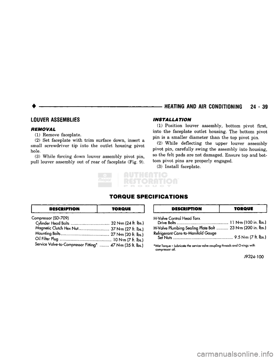
TORQUE
SPECIFICATIONS
DESCRIPTION
fORQUE
DESCRIPTION
Compressor (SD-709) Cylinder Head Bolts 32 N-m (24 ft. lbs.)
Magnetic Clutch Hex Nut... 37 N-m (27 ft. lbs.)
Mounting Bolts 27 N-m (20 ft. lbs.)
Oil Filter Plug
10
N-m (7 ft. lbs.)
Service Valve-to-Compressor Fitting* ........ 47 N-m (35 ft. lbs.)
TORQUE
H-Valve Control Head Torx Drive Bolts
11
N-m
(100
in. lbs.)
H-Valve Plumbing Sealing Plate Bolt 23 N-m (200 in. lbs.)
Refrigerant Cans-to-Manifold Gauge Set Nuts 9.5 N-m (7
ft.
lbs.)
•Wet Torque - Lubricate the service valve
coupling
threads and
O-rings
with
compressor
oil.
J9324-100
Page 1478 of 1502
•
EMISSION
CONTROL
SYSTEMS
25
- 1
CONTENTS
page page
AIR INJECTION
SYSTEM-o
9L
HDC-GAS EVAPORATIVE EMISSION CONTROLS
6
ENGINE
15
EXHAUST EMISSION CONTROLS
10
COMPONENT
REMOVAL/INSTALLATION
17
GENERAL INFORMATION
1
GENERAL
INFORMATION
Throughout this group, references are made
to
par
ticular vehicle models
by
alphabetical designation
or
by the particular vehicle nameplate.
A
chart showing a breakdown
of
alphabetical designations
is
included
in
the
Introduction section
at
the
beginning
of
this
manual.
The 5.9L (V-8) gas powered engine will
be
referred
to
in
this group
as
either the: LDC (Light Duty Cy cle)
or
HDC (Heavy Duty Cycle) engine.
The
HDC
engine can
be
easily identified
by
the
use
of
an en
gine mounted
air
injection pump. The 3.9L/5.2L/5.9L
LDC engine will not use
an
air
injection pump.
Maintenance requirements for LDC and HDC emis
sion systems differ because
of
different load
and
op
erating conditions. This section will cover emission control systems
for
the 3.9L (V-6), 5.2L (V-8), 5.9L LDC (V-8), 5.9L HDC (V-8) and 5.9L (in-line six cylinder) diesel engines.
SERVICE
REMINDER INDICATOR
(SRI)
LIGHT
The instrument panel mounted SRI light was for
merly referred
to as the
emission maintenance
re
minder (EMR) light.
It is
used with 5.9L HDC-gas
powered engines only.
It is
not
used with diesel
en
gines.
The SRI system
is
incorporated into the powertrain
control module (PCM)
(the
PCM
was
formerly
re
ferred
to as the
engine controller
or
SBEC).
The
PCM records
the
vehicles mileage and stores
it
into
memory every
8
miles. At that time, the PCM checks
for the 60,000 and 82,500 mileage trip points. When
the current mileage matches one
of
the above men
tioned trip points,
the
SRI light
is
activated.
The following parts are
to
be replaced
at
either the
indicated mileage
or
when the SRI light remains
on
when the key
is in
the ON position. After performing
the required maintenance,
the
SRI light must
be
re set
to
turn the light
off.
96,000
km
(60,000 miles):
• Replace EGR Valve
• Clean EGR passage • Replace PCV Valve
132,000
km
(82,500 miles):
• Replace Oxygen Sensor
Refer
to
Group
0,
Lubrication and Maintenance
for
all required maintenance schedules.
Failure
to
perform
the
required maintenance
and
only reset the SRI light may be
a
violation of federal
law. Only after performing
the
required mainte
nance, should the SRI light
be
reset.
RESETTING
SRI
LIGHT
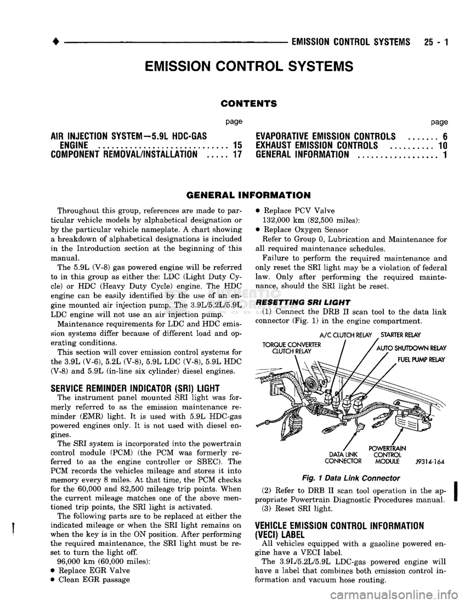
(1) Connect
the
DRB
II
scan tool
to
the
data link
connector (Fig.
1)
in
the engine compartment.
TORQUE CONVERTER
CLUTCH RELAY
A/C
CLUTCH RELAY
.
STARTER RELAY
AUTO
SHUTDOWN RELAY FUEL PUMP RELAY DATA LINK
CONNECTOR POWERTRAIN
CONTROL
MODULE
J9314-164
Fig.
1
Data
Link
Connector
(2) Refer
to
DRB
II
scan tool operation
in
the ap
propriate Powertrain Diagnostic Procedures manual. (3) Reset SRI light.
VEHICLE
EMISSION CONTROL INFORMATION
(VECI)
LABEL
All vehicles equipped with
a
gasoline powered
en
gine have
a
VECI label. The 3.9L/5.2L/5.9L LDC-gas powered engine will
have
a
label that combines both emission control
in
formation and vacuum hose routing.
EMISSION CONTROL
SYSTEMS
Page 1494 of 1502
•
EMISSION
CONTROL SYSTEMS
25 - 17
COMPONENT REMOVAL/INSTALLATION
INDEI
page
Air
Filter/Filter
Housing—Diesel Engines
17
Air
Filter/Filter
Housing—Gas Engines
17
Air
Injection
Pump
17
Air
Injection
Pump Relief Valve
18
Check
Valve—Air
Injection
Tube
18
Coolant Temperature
Sensor
. 18
EGR
Tube—Gas Powered Engines
19
EGR
Valve
19
AIR FILTER/FILTER HOUSING-GAS ENGINES
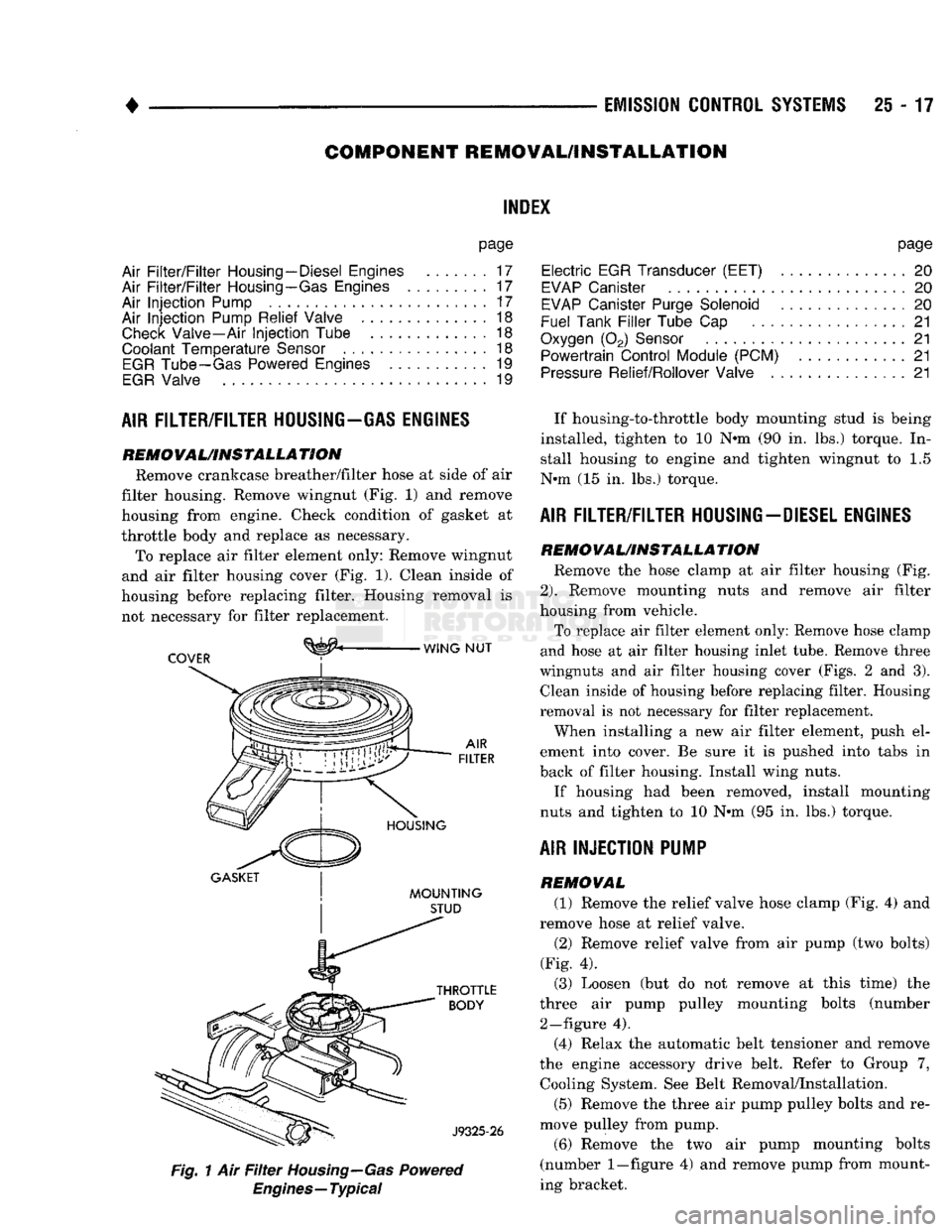
REMOVAL/INSTALLATION Remove crankcase breather/filter hose at side of air
filter housing. Remove wingnut (Fig. 1) and remove
housing from engine. Check condition of gasket at
throttle body and replace as necessary. To replace air filter element only: Remove wingnut
and air filter housing cover (Fig. 1). Clean inside of
housing before replacing filter. Housing removal is not necessary for filter replacement.
^
WING NUT
COVER
:
GASKET
| I
MOUNTING
STUD
Fig.
1 Air
Filter
Housing—Gas
Powered
Engines—Typical
page
Electric
EGR Transducer (EET)
20
EVAP
Canister
20
EVAP
Canister Purge Solenoid
20
Fuel Tank
Filler
Tube
Cap . 21
Oxygen
(02)
Sensor
21
Powertrain Control Module (PCM)
21
Pressure
Relief/Rollover Valve
21
If housing-to-throttle body mounting stud is being
installed, tighten to 10 N»m (90 in. lbs.) torque. In stall housing to engine and tighten wingnut to 1.5
N»m (15 in. lbs.) torque.
AIR FILTER/FILTER HOUSING-DIESEL ENGINES
REMO
VAL/INSTALLA
TION Remove the hose clamp at air filter housing (Fig.
2).
Remove mounting nuts and remove air filter
housing from vehicle.
To replace air filter element only: Remove hose clamp
and hose at air filter housing inlet tube. Remove three
wingnuts and air filter housing cover (Figs. 2 and 3). Clean inside of housing before replacing filter. Housing
removal is not necessary for filter replacement.
When installing a new air filter element, push el
ement into cover. Be sure it is pushed into tabs in
back of filter housing. Install wing nuts.
If housing had been removed, install mounting
nuts and tighten to 10 N»m (95 in. lbs.) torque.
AIR INJECTION PUMP
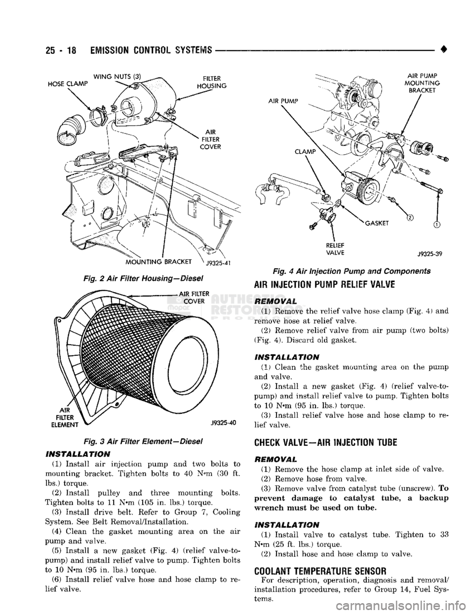
REMOVAL (1) Remove the relief valve hose clamp (Fig. 4) and
remove hose at relief valve.
(2) Remove relief valve from air pump (two bolts)
(Fig. 4). (3) Loosen (but do not remove at this time) the
three air pump pulley mounting bolts (number 2—figure 4).
(4) Relax the automatic belt tensioner and remove
the engine accessory drive belt. Refer to Group 7, Cooling System. See Belt Removal/Installation.
(5) Remove the three air pump pulley bolts and re
move pulley from pump.
(6) Remove the two air pump mounting bolts
(number
1—figure
4) and remove pump from mount
ing bracket.
Page 1495 of 1502
25
- 18
EMISSION
CONTROL
SYSTEMS
Fig. 2 Air Filter Housing—Diesel Fig. 3 Air Filter Element—Diesel INSTALLATION
(1) Install air injection pump and two bolts to
mounting bracket. Tighten bolts to 40 N*m (30 ft.
lbs.) torque. (2) Install pulley and three mounting bolts.
Tighten bolts to 11 N*m (105 in. lbs.) torque.
(3) Install drive belt. Refer to Group 7, Cooling
System. See Belt Removal/Installation.
(4) Clean the gasket mounting area on the air
pump and valve. (5) Install a new gasket (Fig. 4) (relief valve-to-
pump) and install relief valve to pump. Tighten bolts to 10 N*m (95 in. lbs.) torque.
(6) Install relief valve hose and hose clamp to re
lief valve. •
RELIEF
VALVE
J9325-39
Fig. 4 Air Injection
Pump
and
Components
AIR
INJECTION PUMP RELIEF VALVE REMOVAL
(1) Remove the relief valve hose clamp (Fig. 4) and
remove hose at relief valve.
(2) Remove relief valve from air pump (two bolts)
(Fig. 4). Discard old gasket.
INSTALLATION (1)
Clean the gasket mounting area on the pump
and valve. (2) Install a new gasket (Fig. 4) (relief valve-to-
pump) and install relief valve to pump. Tighten bolts
to 10 N*m (95 in. lbs.) torque. (3) Install relief valve hose and hose clamp to re
lief valve.
CHECK
VALVE—AIR INJECTION TUBE REMOVAL
(1) Remove the hose clamp at inlet side of valve.
(2) Remove hose from valve.
(3) Remove valve from catalyst tube (unscrew). To
prevent damage to catalyst tube, a backup
wrench must be used on tube.
INSTALLATION
(1) Install valve to catalyst tube. Tighten to 33
N«m (25 ft. lbs.) torque.
(2) Install hose and hose clamp to valve.
COOLANT TEMPERATURE SENSOR
For description, operation, diagnosis and removal/
installation procedures, refer to Group 14, Fuel Sys
tems.