1993 DODGE TRUCK torque
[x] Cancel search: torquePage 1431 of 1502
23
- 48
BODY COMPONENTS
JUMP SEAT LAP BELT/BUCKLE
REMOVAL
(1) If necessary, move the front seat(s) all the way
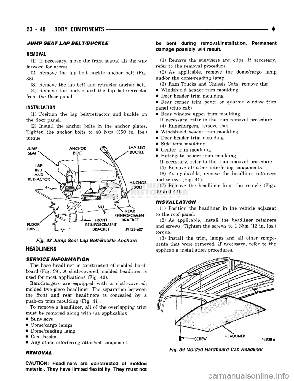
forward for access. (2) Remove the lap belt buckle anchor bolt (Fig.
38).
(3) Remove the lap belt and retractor anchor bolt.
(4) Remove the buckle and the lap belt/retractor
from the floor panel.
INSTALLATION
(1) Position the lap belt/retractor and buckle on
the floor panel.
(2) Install the anchor bolts in the anchor plates.
Tighten the anchor bolts to 40 N*m (350 in. lbs.)
torque.
Fig.
38
Jump
Seat
Lap
Belt/Buckle
Anchors
HEADLINERS
SERVICE INFORMATION
The base headliner is constructed of molded hard-
board (Fig. 39). A cloth-covered, molded headliner is
used for most applications (Fig, 40).
Ramchargers are equipped with a cloth-covered,
molded two-piece headliner. The separation between
the front and rear headliners is concealed by a
push-on trim moulding (Fig. 41).
To remove a headliner, all of the overlapping trim
must be removed along with (as applicable):
• Sunvisors
• Dome/cargo lamps • Dome/reading lamp
• Coat hooks
• Any other interfering attached component
REMOVAL be bent during removal/installation. Permanent
damage
possibly
will
result.
(1) Remove the sunvisors and clips. If necessary,
refer to the removal procedure. (2) As applicable, remove the dome/cargo lamp
and/or the dome/reading lamp.
(3) Ram Trucks and Chassis Cabs, remove the:
• Windshield header trim moulding
• Door header trim moulding
• Rear corner trim panel or quarter window trim
panel (club cab) • Rear window upper trim moulding.
If necessary, refer to the trim removal procedure.
(4) Ramchargers, remove the:
• Windshield header trim moulding
• Door header trim moulding
• Side trim moulding
• Center trim moulding
• Hatchgate header trim moulding
If necessary, refer to the trim removal procedure. (5) Remove all other interfering components.
(6) As applicable, remove the headliner retainers
and screws (Fig. 41).
(7) Remove the headliner from the vehicle (Figs.
40 and 41).
INSTALLATION
(1) Position the headliner in the vehicle adjacent
to the roof panel.
(2) As applicable, install the headliner retainers
and screws. Tighten the screws to 1 N*m (12 in. lbs.)
torque. (3) Install the trim, lamps and all other compo
nents that were removed. If necessary, refer to the applicable installation procedures.
Fig.
39
Molded
Hardboard Cab Headliner
CAUTION:
Headliners
are
constructed
of
molded
material. They have limited flexibility. They must
not
Page 1433 of 1502
23
- 50 BODY COMPONENTS — < ^ ^ • •
DOME LAMP DOME/READING LAMP
J9123-400
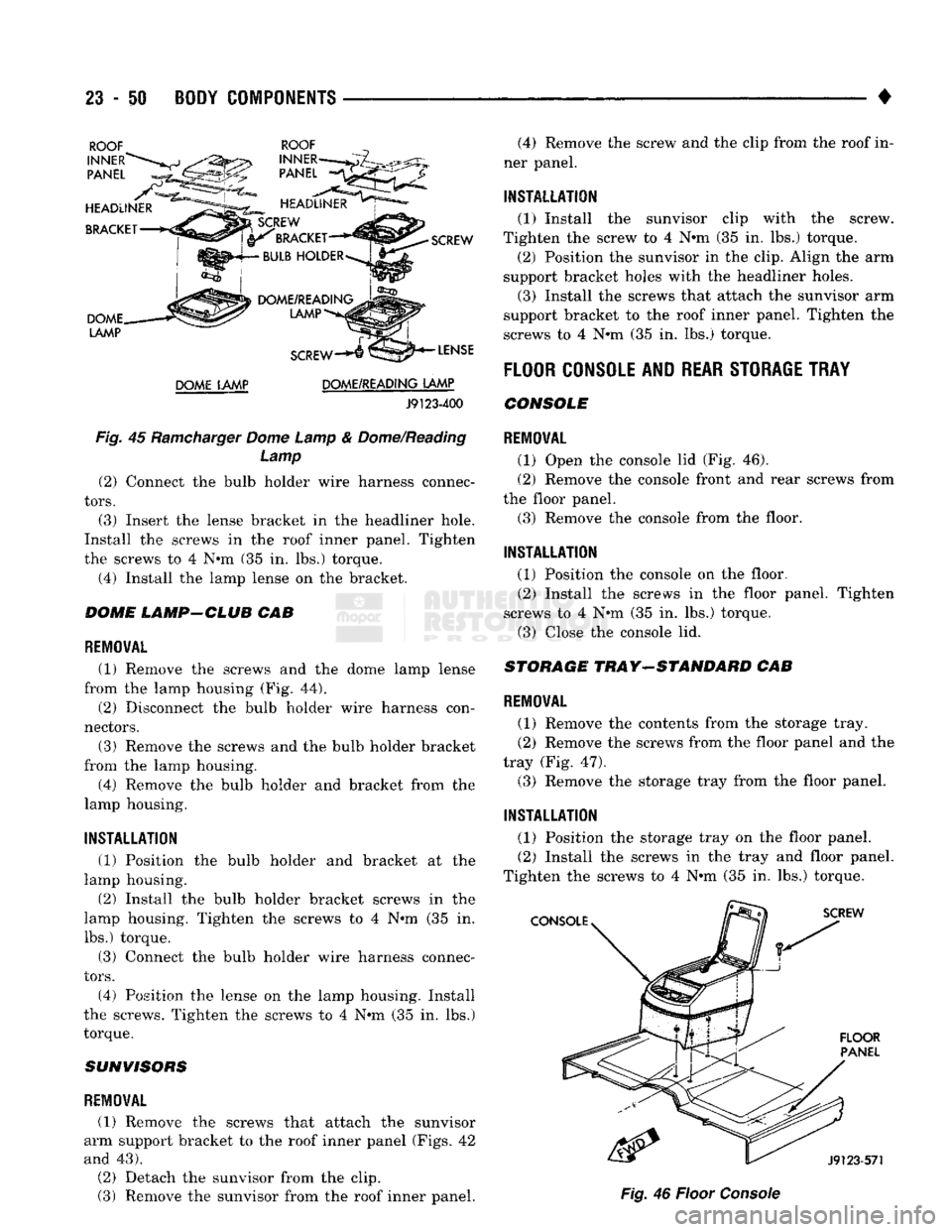
Fig.
45
Ramcharger
Dome Lamp
&
Dome/Reading Lamp (2) Connect
the
bulb holder wire harness connec
tors.
(3) Insert
the
lense bracket
in the
headliner hole.
Install
the
screws
in the
roof inner panel. Tighten
the screws
to 4 N#m (35 in. lbs.)
torque.
(4) Install
the
lamp lense
on the
bracket.
DOME LAMP-CLUB
CAB
REMOVAL
(1) Remove
the
screws
and the
dome lamp lense
from
the
lamp housing
(Fig. 44).
(2) Disconnect
the
bulb holder wire harness con
nectors.
(3) Remove
the
screws
and the
bulb holder bracket
from
the
lamp housing. (4) Remove
the
bulb holder
and
bracket from
the
lamp housing.
INSTALLATION
(1) Position
the
bulb holder
and
bracket
at the
lamp housing.
(2) Install
the
bulb holder bracket screws
in the
lamp housing. Tighten
the
screws
to 4 N°m (35 in.
lbs.) torque.
(3) Connect
the
bulb holder wire harness connec
tors.
(4) Position
the
lense
on the
lamp housing. Install
the screws. Tighten
the
screws
to 4 N#m (35 in. lbs.)
torque.
SUNVISORS
REMOVAL
(1) Remove
the
screws that attach
the
sunvisor
arm support bracket
to the
roof inner panel (Figs.
42
and
43).
(2) Detach
the
sunvisor from
the
clip.
(3) Remove
the
sunvisor from
the
roof inner panel. (4) Remove
the
screw
and the
clip from
the
roof
in
ner panel.
INSTALLATION
(1) Install
the
sunvisor clip with
the
screw.
Tighten
the
screw
to 4 N*m (35 in. lbs.)
torque, (2) Position
the
sunvisor
in the
clip. Align
the arm
support bracket holes with
the
headliner holes.
(3) Install
the
screws that attach
the
sunvisor
arm
support bracket
to the
roof inner panel. Tighten
the
screws
to 4
N*m
(35 in. lbs.)
torque.
FLOOR
CONSOLE AND
REAR STORAGE TRAY
CONSOLE
REMOVAL
(1) Open
the
console
lid (Fig. 46).
(2) Remove
the
console front
and
rear screws from
the floor panel.
(3) Remove
the
console from
the
floor.
INSTALLATION
(1) Position
the
console
on the
floor. (2) Install
the
screws
in the
floor panel. Tighten
screws
to 4 N«m (35 in. lbs.)
torque. (3) Close
the
console
lid.
STORAGE
TRAY-STANDARD
CAB
REMOVAL
(1) Remove
the
contents from
the
storage tray.
(2) Remove
the
screws from
the
floor panel
and the
tray
(Fig. 47).
(3) Remove
the
storage tray from
the
floor panel.
INSTALLATION
(1) Position
the
storage tray
on the
floor panel. (2) Install
the
screws
in the
tray
and
floor panel.
Tighten
the
screws
to 4 N«m (35 in. lbs.)
torque.
Fig.
46
Floor
Console
Page 1438 of 1502
•
• —• •
HEATING
AND AIR
CONDITIONING
24 - 1 CONTENTS
page
CLIMATE CONTROL SYSTEM
............. 21
REFRIGERANT SYSTEM SERWICE
COMPRESSOR
SERWICE
(SD-709)
......... 21
PROCEDURES
.............
DIAGNOSTIC PROCEDURES
3
TORQUE SPECIFICATIONS
GENERAL INFORMATION
1
page
. 17
. 31
GENERAL INFORMATION
HEATER SYSTEM
All models use a Blend-Air type heater. Outside air
enters the heater through the cowl opening and
passes through a plenum chamber to the heater core. Air intake openings must be kept free of snow, ice and other obstructions for the heater system to pick
up sufficient outside air. A temperature control door
in the heater housing directs incoming air through
the heater core and/or the heater core bypass. The amount of blend (heated and non-heated air) is deter
mined by the setting of the temperature lever on the
instrument panel. Direction of the blended air is con
trolled by the HEAT-DEFROST lever on the instru ment panel. The blower switch and resistor block controls the
speed of the blower motor. This in turn controls the
velocity of the air flow from the heater outlets. The resistor block consists of 2 helical wound wire
resistors connected to terminals which are mechani cally attached to a glass-filled phenolic board. This
assembly is bolted to the plenum. The blower switch controls the blower motor speed
by selectively connecting the resistors in series to the
blower motor.
A self-adjusting clip, on each of 2 control cables has
been incorporated to simplify cable adjustment. This clip snaps onto the control cable core wire and will slide along the wire under a specific load to provide
an automatic cable adjustment.
AIR
CONDITIONING
SYSTEM
Air intake openings must be kept free of snow, ice
and other obstructions for the air conditioning sys
tem to pick up sufficient outside air.
COMPONENTS
• COMPRESSOR-The seven piston SD-709 com
pressor is used on all vehicles. This compressor com
presses the low pressure refrigerant vapor into a high pressure, high temperature vapor. • CLUTCH PULLEY AND COIL-These are
mounted on the compressor, providing a convenient
way to drive it and disengage it in accordance to the cooling needs.
• CONDENSER-The condenser is located in front
of the radiator. Its function is to cool the hot, high
pressure refrigerant gas causing it to condense into
high pressure liquid refrigerant.
• FILTER-DRIER—The filter-drier is used to remove
any traces of moisture from the refrigerant system.
This component incorporates the sight glass and the
high pressure relief valve.
• SIGHT GLASS-The sight glass is provided as a
diagnostic tool to observe refrigerant flow and indi cate refrigerant level. It is located at the top of the
filter drier.
• HIGH -PRESSURE RELIEF VALVE-This is a safety device designed to open automatically if the
system pressure reaches a predetermined level. This
will prevent system component damage. • EXPANSION (H) VALVE-The expansion (H)
valve is used to meter refrigerant into the evaporator
in accordance with cooling requirements. • EVAPORATOR COIL-The evaporator coil is lo
cated in the A/C unit. Its function is to cool and de-
humidify the air before it enters the vehicle. • FREEZE CONTROL-The main function of freeze
control is to prevent water on the evaporator coil face
from freezing which restricts the airflow. An elec
tronic temperature cycling switch is located on the
refrigerant plumbing (suction line) near the H-Valve.
The switch turns the compressor ON-OFF depending
on the temperature in the suction line. The switch is a sealed, specially calibrated unit. If found defective,
the switch must be replaced. • REFRIGERANT LINES-These lines are needed
to carry the refrigerant between the various system components.
• CONDENSATE DRAIN TUBE-Condensation
which accumulates on the bottom of the evaporator
HEATING
AND AIR
CONDITIONING
Page 1447 of 1502
24 - 10
HEATING
AND AIR
CONDITIONING
•
(3) Add 50 ml (1.7 oz.) of clean refrigerant oil
through the suction port.
(4) Install compressor.
(5) Install the suction and discharge lines to the
compressor. Use new gaskets to prevent leakage.
Tighten the line nuts to 23 N*m (200 in. lbs.) torque.
(6)
Evacuate and charge system.
OVER-ALL
PERFORMANCE
TEST
Humidity has an important bearing on the temper
ature of the air delivered to the vehicle's interior.
This is true of all air conditioning systems It is im
portant to understand the effect humidity has on the
performance of the system. When humidity is high,
the evaporator has to perform a double duty. It must lower the air temperature and the temperature of the
moisture carried in the air. Condensing the moisture
in the air transfers a great deal of heat energy into
the evaporator fins and tubing. This reduces the amount of heat the evaporator can absorb from the
air.
Evaporator capacity used to reduce the amount of
moisture in the air is not wasted. Wringing some of
the moisture out of the air entering the vehicle adds
to the comfort of the passengers. However, an owner may expect too much from their air conditioning sys
tem on humid days. A performance test is the best
way to determine whether or not the system is per
forming up to standard. This test also provides valu able clues to the possible cause of trouble.
To perform the test the air temperature in the test
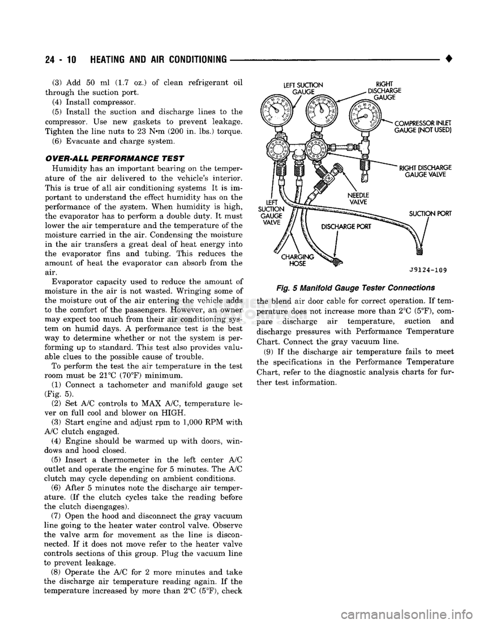
room must be 21°C (70°F) minimum. (1) Connect a tachometer and manifold gauge set
(Fig. 5).
(2) Set A/C controls to MAX A/C, temperature le
ver on full cool and blower on HIGH. (3) Start engine and adjust rpm to 1,000 RPM with
A/C clutch engaged.
(4) Engine should be warmed up with doors, win
dows and hood closed.
(5)
Insert a thermometer in the left center A/C
outlet and operate the engine for 5 minutes. The A/C
clutch may cycle depending on ambient conditions.
(6)
After 5 minutes note the discharge air temper
ature. (If the clutch cycles take the reading before
the clutch disengages).
(7) Open the hood and disconnect the gray vacuum
line going to the heater water control valve. Observe
the valve arm for movement as the line is discon nected. If it does not move refer to the heater valve
controls sections of this group. Plug the vacuum line
to prevent leakage.
(8) Operate the A/C for 2 more minutes and take
the discharge air temperature reading again. If the
temperature increased by more than 2°C (5°F), check
LEFT
SUCTION
RIGHT
J9124-109
Fig.
5 Manifold
Gauge
Tester
Connections
the blend air door cable for correct operation. If tem
perature does not increase more than 2°C
(5°F),
com
pare discharge air temperature, suction and discharge pressures with Performance Temperature Chart. Connect the gray vacuum line.
(9) If the discharge air temperature fails to meet
the specifications in the Performance Temperature Chart, refer to the diagnostic analysis charts for fur
ther test information.
Page 1456 of 1502
•
HEATING
AND
AIR
CONDITIONING
24 - 19
Connect
the
compound gauge hose
to the
compres
sor suction service valve gauge port (low-side).
Connect
the
high pressure gauge hose
to the
dis
charge service valve gauge port (high-side). Purge
air
from
the
high side test hose
by
opening
the high side hand valve
on the
manifold
for 3 to 5
seconds.
The
center connection
on the
manifold must
be open.
Purge
air
from
the low
side test hose
by
opening
the
low
side hand valve
on the
manifold
for 3 to 5
seconds.
The
center connection
on the
manifold must
be open.
The
air
conditioning system
may be
operated with
the gauge manifold assembly connected
in
this man
ner.
The
gauges will indicate respective operative
pressures.
DISCHARGING
THE SYSTEM
Since
the air
conditioning refrigerant system
is
pressurized,
it
will
be
necessary
to
completely dis charge
the
system before replacing
any
refrigerant
components.
The
procedure
is as
follows: (1) Install gauge
set as
described under manifold
gauge
set
installation. Make sure
the
gauge
set
valves
are
closed before attaching
the
hoses
to the re
frigerant system. (2) Install
a
long hose
to the
manifold gauge
set
connector.
Run
this hose
to the oil
collector
can
near
the shop exhaust system. A good
oil
collector
can may be
made from
a
large
empty coffee
can
with
a
plastic
top.
Slit
the
plastic
top
in the
form
of a Y to
make
an
entrance
for the
refrigerant hose
and
exit
for the gas.
(3) Open
the
compressor discharge
and
suction line
pressure valves
and
discharge
the
refrigerant into
the
oil
collector
can.
Watch
to
make sure
the
hose does
not
blow
out of the
collector
can.
(4) When
the
system
has
been completely dis
charged, measure
the
amount
of oil
collected
in the
can.
The
amount
of oil
measured should
be
added
to
the refrigerant system before
it is
charged. Discard
the used
oil. Add new oil.
EVACUATING
THE SYSTEM
Whenever
the
system
has
been opened
to the
atmo
sphere,
it is
absolutely essential that
the
system
be
evacuated
to
remove
all the air and
moisture.
Air in
the refrigerant system causes high compressor dis charge pressures,
a
loss
in
system performance,
and
oxidation
of the
compressor
oil
into
gum and
varnish.
Moisture
in the
refrigerant system
can
cause
the ex
pansion valve
to
malfunction. Under certain condi
tions
it can
react with
the
refrigerant
to
form destructive acids.
It is
necessary
to
adhere
to the
fol
lowing procedure
to
keep
air and
moisture
out of the
system. (1) Connect
the
manifold gauge
set to the
compres
sor
and
long test hose from manifold gauge
set
center
connection
to
Vacuum Pump Tool C-4289. (2) Open both manifold gauge
set
valves.
(3) Start
the
vacuum pump
and
operate until
the
evaporator suction gauge registers
at
least
-88
kPag (26 inches
of
vacuum).
If at
least
-88
kPag
(26
inches
of vacuum) cannot
be
obtained, either
the
system
has
a leak
or the
vacuum pump
is
defective. Check
the
vacuum pump.
If the
pump proves
to be
functioning
properly,
the
system
has a
leak. Charge
the
system
with
1
pound
of
refrigerant. Locate
and
repair
all
leaks.
Discharge
the
refrigerant
and
evacuate
the
system.
(4) Continue
to
operate
the
pump
for at
least
5
minutes.
(5) Close manifold valves. Turn
off the
vacuum
pump
and
observe evaporator suction gauge
for 2
minutes.
The
vacuum level should remain constant.
If
the
vacuum level falls
off, the
system
has a
leak. Charge
the
system with
450 g (1
pound)
of
refriger
ant. Locate
and
repair
all
leaks. Discharge
the
sys
tem
and
repeat evacuation procedure.
CHARGING
THE
SYSTEM
The refrigerant system must have been evacuated
using
the
previous procedure before charging. Charge
using only
R-12
refrigerant.
R-12 is
available
in
bulk
tanks
or 437 g (14 oz.)
cans. The special refrigerant dispensing manifold per
mits charging
3
cans
of
refrigerant
at a
time. When
using disposable cans
of
this type, carefully follow
the
can
manufacturers instructions.
WARNING: NEVER USE THESE CANS
TO
CHARGE
INTO
THE
HIGH
PRESSURE SIDE
OF
THE
SYSTEM
(COMPRESSOR
DISCHARGE PORT)
OR
INTO
A
SYSTEM
THAT
IS AT
HIGH
TEMPERATURE.
THE
HIGH
SYSTEM PRESSURES COULD
BE
TRANS
FERRED
INTO
THE
CHARGING
CAN
CAUSING
IT
TO EXPLODE.
Keep
the
refrigerant manifold valves capped when
not
in use.
Keep
a
supply
of
extra refrigerant-can-to
refrigerant-manifold gaskets
on
hand
so the
gaskets can
be
replaced periodically. This will insure
a
good
seal without excessive tightening
of the can or the
manifold nuts.
(1) Attach center hose from manifold gauge
set to
refrigerant dispensing manifold. Turn refrigerant manifold valves completely counterclockwise
so
they are fully open. Remove protective caps from refriger
ant manifold.
(2) Screw refrigerant cans into manifold.
Be
sure
manifold-to-can gasket
is in
place
and in
good condi
tion. Tighten
can and
manifold nuts
to 9.5 N»m (7 ft.
lbs.) torque.
Page 1457 of 1502
24
- 20
HEATING
AND AIR
CONDITIONING
• (3) Turn
3
refrigerant manifold valves completely
clockwise
to
puncture
the
cans
and
close
the
mani
fold valves.
(4) Purge
the air
from
the
charging line
by
loosen
ing
the
charging hose
at the
manifold gauge
set and
turn
one of the
refrigerant valves counterclockwise. When
the
refrigerant
gas
starts escaping from
the
loose connection, tighten
the
hose.
(5) Fully open
all 3
refrigerant manifold valves
and place
the
cans
of
refrigerant into
a pan
contain
ing 52°C (125°F) water.
The
water will warm
the
charging
can and aid in the
transfer
of the
charge
into
the
system.
(6) Start
the
engine
and
move
the
controls
to A/C
low blower position.
The electronic temperature cycling switch will pre
vent
the
clutch from engaging until refrigerant
is
added
to the
system.
If the
clutch does engage,
re
place
the
switch before proceeding
any
further. (7) Charge through
the
suction side
of the
system
by slowly opening
the
suction manifold valve. Adjust
the valve
as
necessary
so
charging pressure does
not
exceed
345
kPag
(50
psig). Maintain
the
temperature
of
the
water
in the pan by
adding warm water
as
necessary. (8) Adjust
the
engine speed
to a
fast idle
of
approx
imately
1,300 RPM.
(9) When
all 3
cans
of
refrigerant
are
completely
empty, close
the
manifold gauge
set
valves
and re
frigerant manifold valves. The maximum refrigerant charge
is 44 oz.
REFRIGERANT
LEAK REPAIR PROCEDURE
LOST CHARGE If
the
system
has
lost
all
charge
due to a
leak: (1) Evacuate
the
system.
(2) Charge
the
system with approximately
1
pound
of refrigerant. (3) Locate
all
leaks.
(4) Repair
all
leaks.
(5) Replace filter-drier bottle.
CAUTION:
Replacement
filter-drier
units
must
be
sealed
while
in
storage.
The
drier
used
in
these
units
absorbs
and
traps
moisture
quickly
upon
ex
posure
to the
atmosphere.
When
installing
a
drier,
have
all
tools
and
supplies ready
for
quick
reas
sembly
to
avoid keeping
the
system open
any
longer
than
necessary.
(6) Check system
oil
level. (7) Evacuate
and
charge
the
system.
LOW CHARGE If
the
system
has not
lost
all of its
refrigerant
charge; locate
and
repair
all
leaks.
If it is
necessary
to increase
the
system pressure
to
find
the
leak
(be
cause
of an
especially
low
charge),
add 230 g (1/2 lb)
of refrigerant.
If
there
has
been
a
significant
oil
loss,
check
the
system
oil
level.
If
leak repair
was
possible
without discharging system
and an oil
level check
was
not
necessary,
use
procedure
for
correcting
low
refrigerant level.
CORRECTING
LOW
REFRIGERANT LEVEL
Since
the
refrigeration system
is
completely sealed,
the refrigerant level will
not be low
unless there
is a
leak
in the
system. Before adding refrigerant where
the
cause
of a low
level
is not
known,
the
system should
be
tested
for
leaks.
Assuming that leaks have been corrected without
discharging
the
system, proceed with partial charge.
Install
and
connect manifold gauge
set.
(1) Close both manifold gauge
set
valves. Open
manifold gauge
set
needle valve.
(2) Connect
the
suction gauge test hose
to the
suc
tion service port
of the
compressor. Connect
the
dis charge gauge test hose
to the
discharge service port. (3) Connect
an end of
long test hose
to the
center
manifold outlet,
and
other
end to
refrigerant dispens ing manifold. (4) Close
the 2
dispensing manifold valves
and
open remaining dispensing manifold valve. Remove
protective
cap
from opened valve.
WARNING: NEVER
USE
THESE CANS
TO
CHARGE
INTO
THE
HIGH
PRESSURE SIDE
OF
THE
SYSTEM
(COMPRESSOR
DISCHARGE
PORT)
OR
INTO
A
SYSTEM
THAT
IS AT
HIGH
TEMPERATURE.
THE
HIGH
SYSTEM PRESSURES COULD
BE
TRANS
FERRED
INTO
THE
CHARGING
CAN
CAUSING
IT
TO EXPLODE.
(5) Screw
a can of R-12 to the
opened manifold
valve.
Be
sure gasket
is in
place
and in
good condi
tion. Tighten refrigerant
can and
manifold locking nut
to
ensure
a
good seal.
Do not
overtighten.
Tighten
to 9.5 N*m (7 ft. lbs.)
torque,
if
gasket
is in
good condition.
(6) Turn manifold valve (above
the
refrigerant
can)
completely clockwise
to
puncture
the can.
This closes
the valve
and
seals
the
refrigerant
in the can.
CAUTION:
Do not
heat refrigerant
12
above
52°C
(125°F).
(7) Place refrigerant
can in a
large
pan of
water
heated
to
52°C (125°F). Place
pan of
water containing
the refrigerant
can on an
accurate scale
so the
amount
of
refrigerant added
can be
weighed. Open
the refrigerant manifold valve.
(8) Purge
all air
from test hoses.
Air in the
system
will
be
trapped
in the
condenser causing abnormally
high discharge pressures
and
interfering with con densing
of the
refrigerant.
Page 1458 of 1502
•
HEATING
AND AIR
CONDITIONING
24 - 21 (a) Loosen both test hoses at the manifold gauge
set. Tighten the hoses as soon as the air is purged. (b) Loosen charging hose connection at manifold
gauge set. This will purge air from the charging
hose.
Tighten connection as soon as air is purged.
(9) With vehicle windows open and hood up, oper
ate engine at 1,300 RPM. (10) Place air conditioner control on A/C and place
the fan switch on high. (11) If necessary, block the condenser to maintain
a discharge pressure of 1 550-1 725 kPag (225-250
psig).
System must be charged through the evapora
tor suction service ports as follows:
(a) Slowly open the suction service gauge valve.
Meter flow of refrigerant by adjusting the suction service gauge valve so the pressure registered at
the suction service gauge does not exceed 345 kPag
COMPRESSOR
J
(50
psig). Keep refrigerant container upright.
(b) Add refrigerant gas until there is no foam visi
ble at the sight glass. As soon as all foam clears, note the weight registered on the refrigerant scale.
(c) Watch the refrigerant weighing scale and add
437 g (14 oz.) of refrigerant (equivalent to 1 can).
(d) Close the suction gauge valve.
CAUTION:
TOO
much
refrigerant
in the
system
can
cause
abnormally high discharge pressures. Care
must
be
used
so the
exact recommended amount
of
refrigerant
is
added
after
foam clears
in the
sight
glass.
(e) Close dispensing manifold valve. Remove test
hoses and adapters from the service ports of com
pressor and install protective caps at service ports.
RVICE (SD-709)
INDEX
page
Compressor
21
Compressor
Shaft Seal
.................... 25
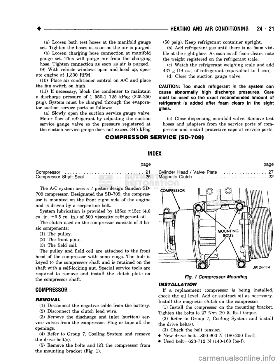
The A/C system uses a 7 piston design Sanden SD-
709 compressor. Designated the SD-709, the compres
sor is mounted on the front right side of the engine
and is driven by a serpentine belt.
System lubrication is provided by 135cc ±15cc (4.6
cu. in. ±0.5 cu. in.) of 500 viscosity refrigerant oil.
The clutch used on the compressor consists of 3 ba
sic components:
(1) The pulley.
(2) The front plate. (3) The field coil.
The pulley and field coil are attached to the front
head of the compressor with snap rings. The hub is keyed to the compressor shaft and is retained on the
shaft with a self-locking nut. Special service tools are
required to remove and install the clutch plate on
the compressor shaft.
COMPRESSOR
REMOVAL
(1) Disconnect the negative cable from the battery.
(2) Disconnect the clutch lead wire.
(3) Remove the discharge and inlet (suction) ser
vice valves from the compressor. Plug or tape all the
openings.
(4) Refer to Group 7, Cooling System and remove
the drive belt(s). (5) Remove the bolts and lift the compressor from
the mounting bracket (Fig. 1).
page
Cylinder Head
/
Valve Plate
27
Magnetic
Clutch
22
Fig.
1
Compressor
Mounting
INSTALLATION
If a replacement compressor is being installed,
check the oil level. Add or subtract oil as necessary.
Install the magnetic clutch on the compressor.
(1) Install the compressor on the mounting bracket.
Tighten the bolts to 27 N*m (20 ft. lbs.) torque.
(2) Refer to Group 7, Cooling System and install
the drive belt(s).
(3) Check the belt tension.
@ New drive belt-800-900 N (180-200 lbs-f).
• Used belt-623-712 N (140-160 lbs-f).
Page 1461 of 1502
24 - 24
HEATING
AND AIR
CONDITIONING
(3) Support the compressor on the 4 mounting ears
at the compressor rear. If a vise is being used, clamp
only on the mounting ears. Never clamp on the com
pressor body.
(4) Align rotor assembly squarely on the front
housing hub.
(5)
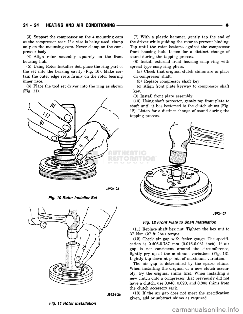
Using Rotor Installer Set, place the ring part of
the set into the bearing cavity (Fig. 10). Make cer
tain the outer edge rests firmly on the rotor bearing
inner race.
(6) Place the tool set driver into the ring as shown
(Fig. 11).
J8924-25
Fig. 10 Rotor installer Set
J8924-26
Fig. 11 Rotor Installation (7) With a plastic hammer, gently tap the end of
the driver while guiding the rotor to prevent binding.
Tap until the rotor bottoms against the compressor front housing hub. Listen for a distinct change of sound during the tapping process.
(8) Install external front housing snap ring with
spread type snap ring pliers.
(a) Check that original clutch shims are in place
on compressor shaft.
(b) Replace compressor shaft key.
(c) Align front plate keyway to compressor shaft
key.
(9) Install front plate assembly.
(10) Using shaft protector, gently tap front plate to
shaft until it has bottomed to the clutch shims (Fig.
12).
Listen for a distinct change of sound during the
tapping process.
J8924-27
Fig. 12 Front Plate to Shaft Installation
(11) Replace shaft hex nut. Tighten the hex nut to
37 N*m (27 ft, lbs.) torque.
(12) Check air gap with feeler gauge. The specifi
cation is 0.406-0.787 mm (0.016-0.031 inch). If air
gap is not consistent around the circumference,
lightly pry up at the minimum variations (Fig. 13).
Lightly tap down at points of maximum variation.
The air gap is determined by the spacer shims.
When installing the original or a new clutch assem
bly, try the original shims first. When installing a new clutch onto a compressor that previously did not
have a clutch, use 0.040, 0.020, and 0.005 shims from
the clutch accessory sack.
(13) If the air gap does not meet the specification
given, add or subtract shims as required.