1993 DODGE TRUCK wheel alignment
[x] Cancel search: wheel alignmentPage 962 of 1502
•
STEERING STEERING
19-1
CONTENTS
page
GENERAL INFORMATION
1
POWER STEERING PUMP
11
POWER STEERING SYSTEM DIAGNOSIS
..... 2
RECIRCULATING
BALL
POWER STEERING GEAR
. 20
page
STEERING COLUMN
3i
STEERING LINKAGE
17
TORQUE SPECIFICATIONS
40
GENERAL
INFORMATION
STEERING SYSTEM COMPONENTS
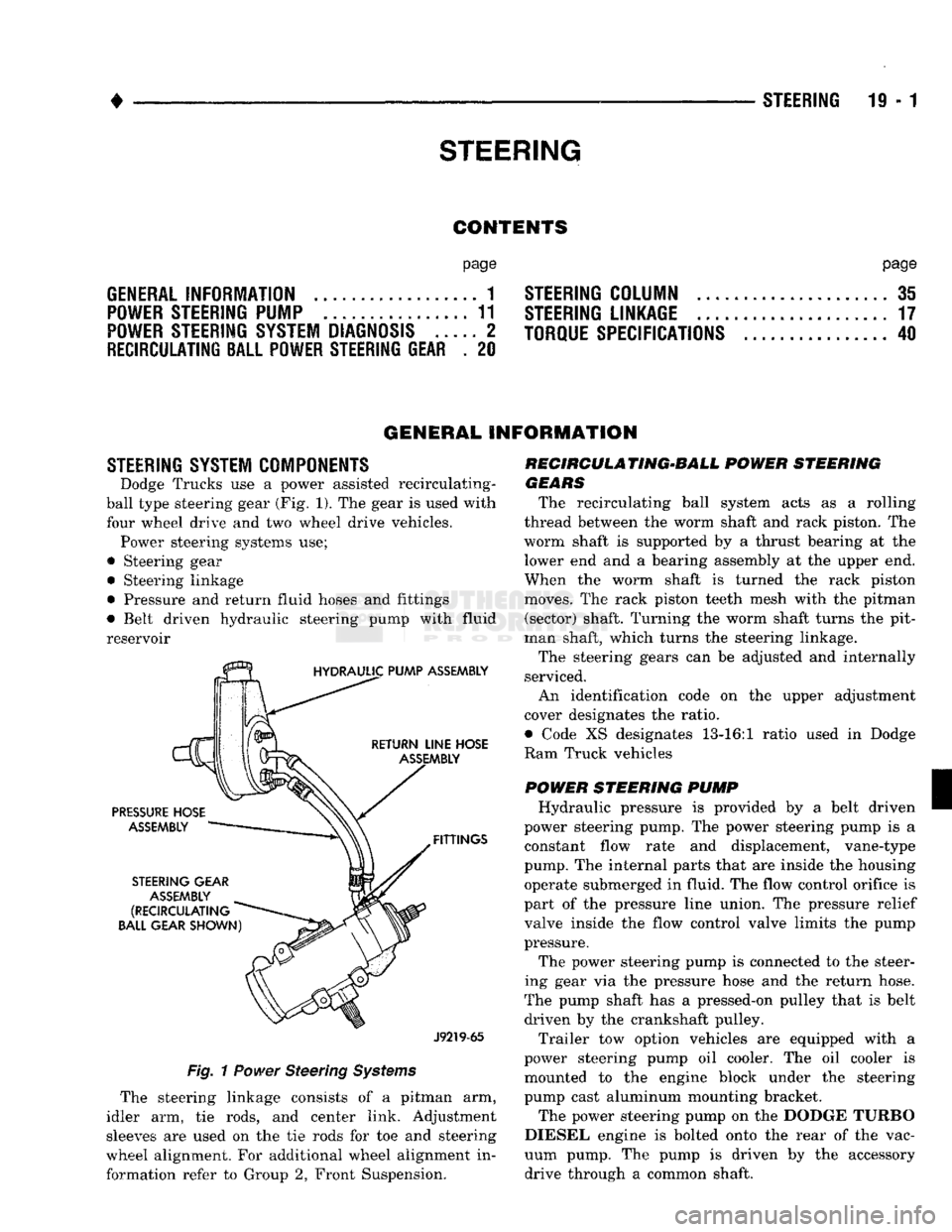
Dodge Trucks
use a
power
assisted recirculating-
ball
type steering gear
(Fig.
1). The
gear
is
used with
four
wheel drive
and two
wheel
drive
vehicles. Power steering systems
use;
•
Steering
gear • Steering linkage
• Pressure
and
return fluid hoses
and
fittings
• Belt driven hydraulic steering pump with
fluid
reservoir
J9219-65
Fig.
1
Power
Steering
Systems
The steering linkage consists
of a
pitman
arm,
idler
arm, tie
rods,
and
center link. Adjustment
sleeves
are
used
on the tie
rods
for toe and
steering
wheel alignment.
For
additional wheel alignment
in
formation refer
to
Group
2,
Front Suspension. RECIRCULA TING-BALL
POWER
STEERING
GEARS
The recirculating ball system acts
as a
rolling
thread between
the
worm shaft
and
rack piston.
The
worm shaft
is
supported
by a
thrust bearing
at the
lower
end
and a
bearing assembly
at
the
upper
end.
When
the
worm shaft
is
turned
the
rack piston
moves.
The
rack piston teeth mesh with
the
pitman (sector) shaft. Turning
the
worm shaft turns
the
pit
man shaft, which turns
the
steering linkage.
The steering gears
can be
adjusted
and
internally
serviced.
An identification code
on the
upper adjustment
cover designates
the
ratio.
• Code
XS
designates 13-16:1 ratio used
in
Dodge
Ram Truck vehicles
POWER
STEERING
PUMP
Hydraulic pressure
is
provided
by a
belt driven
power steering pump.
The
power steering pump
is a
constant flow rate
and
displacement, vane-type
pump.
The
internal parts that
are
inside
the
housing operate submerged
in
fluid.
The
flow control orifice
is
part
of
the
pressure line union.
The
pressure relief
valve inside
the
flow control valve limits
the
pump
pressure.
The power steering pump
is
connected
to
the
steer
ing gear
via the
pressure hose
and the
return hose.
The pump shaft
has
a
pressed-on pulley that
is
belt driven
by the
crankshaft pulley.
Trailer
tow
option vehicles
are
equipped with
a
power steering pump
oil
cooler.
The oil
cooler
is
mounted
to the
engine block under
the
steering
pump cast aluminum mounting bracket.
The power steering pump
on
the
DODGE TURBO
DIESEL engine
is
bolted onto
the
rear
of
the
vac
uum pump.
The
pump
is
driven
by the
accessory drive through
a
common shaft.
Page 968 of 1502
•
STEERING
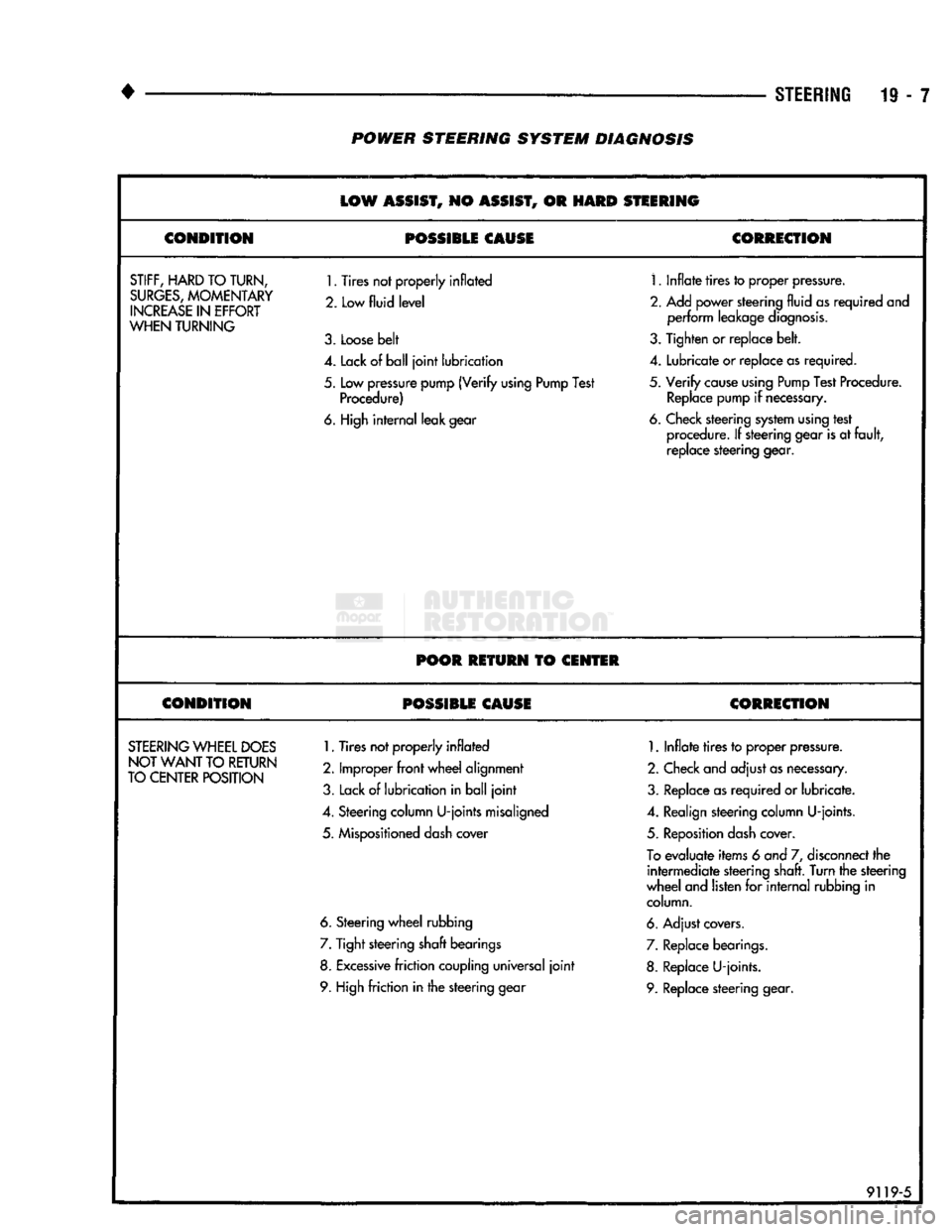
19 - 7 POWER STEERING SYSTEM DIAGNOSIS
LOW
ASSIST,
NO
ASSIST,
OR
HARD
STEERING
CONDITION
POSSIBLE CAUSE
CORRECTION
STIFF,
HARD
TO TURN,
SURGES,
MOMENTARY
INCREASE
IN
EFFORT
WHEN
TURNING
1.
Tires not properly inflated
2. Low
fluid level
3.
Loose belt
1.
Inflate tires to proper pressure.
2.
Add power steering fluid as required and perform leakage diagnosis.
3.
Tighten or replace belt.
4.
Lack of ball joint lubrication
4.
Lubricate or replace as required.
5.
Low pressure pump (Verify using Pump Test Procedure)
5.
Verify cause using Pump Test Procedure.
Replace pump if necessary.
6. High internal leak gear 6. Check steering system using test
procedure. If steering gear is at fault, replace steering gear.
POOR RETURN
TO
CENTER
CONDITION POSSIBLE CAUSE CORRECTION
STEERING
WHEEL
DOES
NOT WANT
TO
RETURN
TO CENTER POSITION
1.
Tires not properly inflated
2.
Improper front wheel alignment
3.
Lack of lubrication in ball joint
1.
Inflate tires to proper pressure.
2.
Check and adjust as necessary.
3.
Replace as required or lubricate.
4.
Steering column U-joints misaligned
4.
Realign steering column U-joints.
5.
Mispositioned dash cover
5.
Reposition dash cover.
To
evaluate items 6 and 7, disconnect the intermediate steering shaft. Turn the steering
wheel and listen for internal rubbing in column.
6. Steering wheel rubbing 6. Adjust covers.
7.
Tight steering shaft bearings
7.
Replace bearings.
8. Excessive friction coupling universal joint 8. Replace U-joints.
9. High friction in the steering gear 9. Replace steering gear.
91195
Page 969 of 1502
19
- 8
STEERING
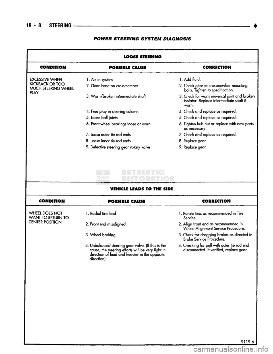
POWER
STEERING
SYSTEM
DIAGNOSIS
LOOSE
STEERING
CONDITION
POSSIBLE
CAUSE
CORRECTION
EXCESSIVE
WHEEL
KICKBACK
OR
TOO
MUCH
STEERING
WHEEL
PLAY
1.
Air in system
2.
Gear
loose
on
crossmember
3.
Worn/broken intermediate shaft
4.
Free
play in steering column
5.
Loose
ball
joints
6. Front wheel bearings
loose
or worn
7.
Loose
outer tie rod
ends
8.
Loose
inner
tie
rod
ends
9.
Defective steering gear
rotary
valve
1.
Add
fluid.
2.
Check
gear
to
crossmember
mounting bolts. Tighten
to
specification,
3.
Check
for worn universal
joint
ond
broken isolator.
Replace
intermediate shaft
if
worn.
4.
Check
and replace
as
required. 5.
Check
and replace
as
required.
6.
Tighten hub nut or replace
with
new parts
as
necessary.
7.
Check
and replace
as
required.
8.
Replace
gear.
9.
Replace
gear.
VEHICLE
LEADS
TO THE
SIDE
CONDITION
POSSIBLE
CAUSE
CORRECTION
WHEEL
DOES
NOT
WANT
TO
RETURN
TO
CENTER
POSITION
1. Radial
tire
lead
2. Front
end
misaligned
3.
Wheel braking
4.
Unbalanced
steering
gear
valve.
(If this is the
cause,
the steering
efforts
will
be very
light
in
direction
of
lead and heavier in the opposite
direction)
1.
Rotate
tires
as
recommended in Tire
Service.
2. Align
front
end
as
recommended
in
Wheel
Alignment
Service
Procedure.
3.
Check
for
dragging
brakes
as
directed
in
Brake
Service
Procedure.
4.
Checking
for
pull
with
outer
tie
rod end
disconnected.
If verified, replace gear.
9119-6
Page 979 of 1502
19
- 18
STEERING
•
CAUTION:
It is
possible
to install the
center
link
re
versed
position.
This
will
result
in
incorrect
geome
try and interferences during vehicle jounce. Viewed
from the
front
of the vehicle, the
center
link
ends
should
turn
upward. Viewed
from
the side of the ve
hicle,
the
ends
should
turn
toward
the
front
of the
vehicle. The
tie-rod
ball
studs
enter
the
center
link
bores
from
the
rear.
(5) Install tie-rod ends into center link (Fig. 2).
Tighten the nuts to 54 N»m (40 ft. lbs.) torque. In stall new cotter pins.
(6) Insert tie-rod ends into steering knuckle arm
(Fig. 2). Tighten the nuts to 54 N-m (40 ft. lbs.)
torque. Install new cotter pins. (7) Remove the supports and lower the vehicle to
the surface. Adjust the wheel toe position (refer to
the Alignment Specifications chart within Group 2,
Front Suspension).
Position the clamp on the sleeve so retaining
bolt is located on the bottom side of the sleeve.
(8) After adjustment, tighten the tie-rod adjust
ment sleeve clamp bolt;
• Standard Duty— 25.4 N-m (225 in. lbs.) torque
• Heavy Duty- 34 N-m (25 ft. lbs.) torque
STEERING
LINKAGE—4WD
VEHICLES
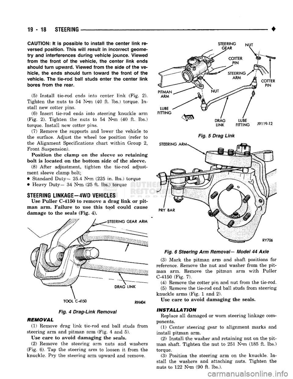
Use Puller C-4150 to remove a drag link or pit
man arm. Failure to use this tool could cause damage to the seals (Fig. 4).
TOOL
C-4150
RH404
Fig.
4
Drag-Link
Removal
REMOVAL (1) Remove drag link tie-rod end ball studs from
steering arm and pitman arm (Fig. 4 and 5).
Use care to avoid damaging the seals. (2) Remove the steering arm nuts and washers
(Fig. 6). Tap the steering arm to loosen it from the
knuckle. Pry the steering arm upward and remove.
STEERING
NUT
LINK
FITTING
J9119-12
Fig.
5
Drag
Link
Fig.
6 Steering Arm
Removal—
Model
44 Axle
(3) Mark the pitman arm and shaft positions for
reference. Remove the nut and washer from the pit
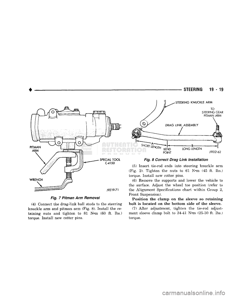
man arm. Remove the pitman arm with Puller C-4150 (Fig. 7). (4) Remove the cotter pin and nut from the tie-rod.
(5) Remove the tie-rod end ball studs from steering
knuckle arms (Fig. 1 and 2).
Use care to avoid damaging the seals.
INSTALLATION
Replace all damaged or worn steering linkage com
ponents. (1) Center steering gear to alignment marks and
install pitman arm.
(2) Install the washer and retaining nut on the pit
man shaft. Tighten the nut to 251 N-m (185 ft. lbs.)
torque. (3) Position the steering arm on the knuckle. In
stall the washers and attaching nuts. Tighten the
nuts to 122 N-m (90 ft. lbs.).
Page 980 of 1502
•
STEERING
19 - 19
Fig.
7 Pitman Arm
Removal
(4) Connect the drag-link ball studs to the steering
knuckle arm and pitman arm (Fig. 8). Install the re
taining nuts and tighten to 81 N»m (60 ft. lbs.)
torque. Install new cotter pins.
POINT
J9102-62
Fig.
8 Correct
Drag
Link
installation
(5) Insert tie-rod ends into steering knuckle arm
(Fig. 2). Tighten the nuts to 61 N-m (45 ft. lbs.)
torque. Install new cotter pins.
(6) Remove the supports and lower the vehicle to
the surface. Adjust the wheel toe position (refer to the Alignment Specifications chart within Group 2, Front Suspension). Position the clamp on the sleeve so retaining
bolt is located on the bottom side of the sleeve. (7) After adjustment, tighten the tie-rod adjust
ment sleeve clamp bolt to 34-41 N-m (25-30 ft. lbs.)
torque.
Page 996 of 1502
•
STEERING 19 - 3i STEERING COLUMN
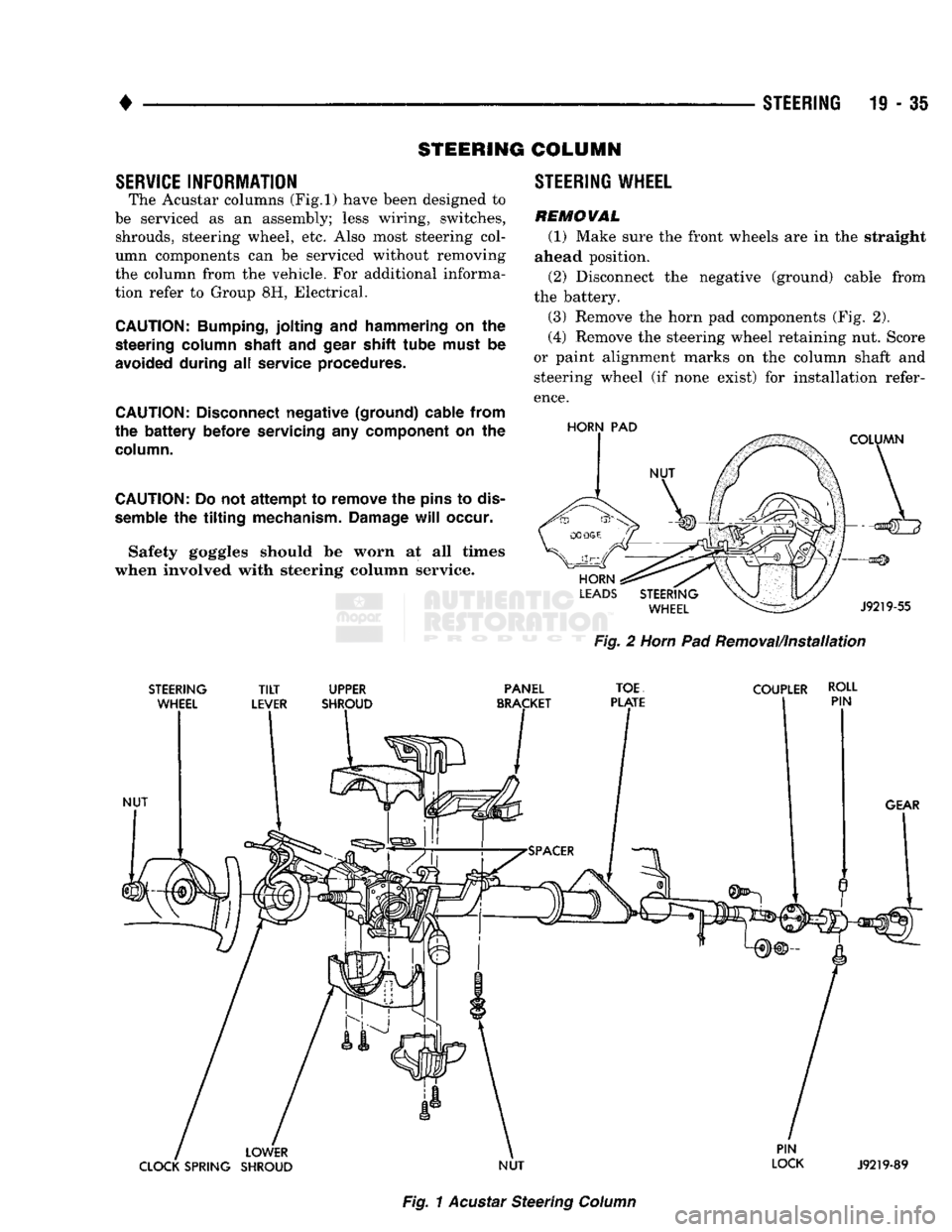
SERVICE INFORMATION The Acustar columns
(Fig.l)
have been designed to
be serviced as an assembly; less wiring, switches, shrouds, steering wheel, etc. Also most steering col
umn components can be serviced without removing
the column from the vehicle. For additional informa
tion refer to Group 8H, Electrical.
CAUTION:
Bumping,
jolting
and
hammering
on the
steering
column
shaft
and
gear shift
tube
must
be
avoided during
all
service procedures.
CAUTION:
Disconnect negative (ground) cable from
the
battery
before servicing
any
component
on the
column.
CAUTION:
Do not
attempt
to remove the
pins
to
dis
semble
the
tilting
mechanism. Damage
will
occur.
Safety goggles should be worn at all times
when involved with steering column service. STEERING WHEEL
REMOWAL
(1) Make sure the front wheels are in the straight
ahead position.
(2) Disconnect the negative (ground) cable from
the battery.
(3) Remove the horn pad components (Fig. 2).
(4) Remove the steering wheel retaining nut. Score
or paint alignment marks on the column shaft and steering wheel (if none exist) for installation refer
ence.
HORN
PAD
Fig.
2
Horn
Pad Removal/installation
STEERING
TILT
UPPER PANEL
TOE
COUPLER ROLL
Fig.
1
Acustar
Steering
Column
Page 998 of 1502
•
STEERING
19 • 37 (4) From the end of travel, rotate the rotor 2 1/2
full turns in the COUNTER CLOCKWISE direction.
The horn wire should end up at the top and the squib
wire at the bottom (Fig. 4).
(5) Install the steering wheel, refer to Steering
Wheel Installation.
COLUMN—
REMOVAL/INSTALLATION
CAUTION:
Bumping,
jolting
and
hammering
on the
steering
column
shaft
and
gear
shift
tube
must
be
avoided
during
all
service
procedures.
REMOVAL (1) Make sure the front wheels are in the straight
ahead position.
(2) Disconnect the negative (ground) cable from
the battery.
(3) Remove steering wheel from column, refer to
Steering Wheel-Removal.
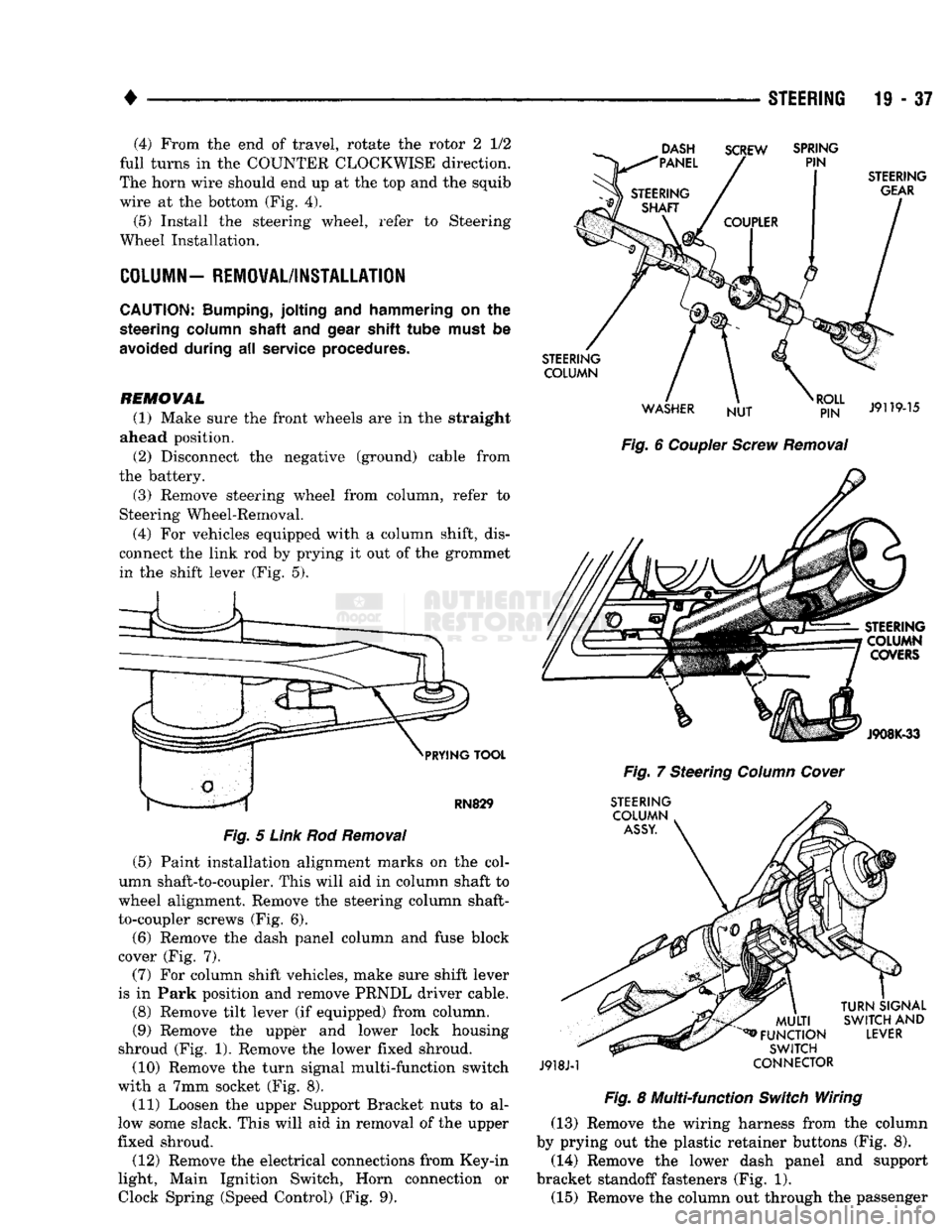
(4) For vehicles equipped with a column shift, dis
connect the link rod by prying it out of the grommet in the shift lever (Fig. 5).
DASH
"PANEL SCREW
SPRING
PIN
PRYING
TOOL
RN829
Fig.
5
Link
Rod
Removal
(5) Paint installation alignment marks on the col
umn shaft-to-coupler. This will aid in column shaft to
wheel alignment. Remove the steering column shaft-
to-coupler screws (Fig. 6).
(6) Remove the dash panel column and fuse block
cover (Fig. 7).
(7) For column shift vehicles, make sure shift lever
is in Park position and remove PRNDL driver cable.
(8) Remove tilt lever (if equipped) from column.
(9) Remove the upper and lower lock housing
shroud (Fig. 1). Remove the lower fixed shroud.
(10) Remove the turn signal multi-function switch
with a 7mm socket (Fig. 8). (11) Loosen the upper Support Bracket nuts to al
low some slack. This will aid in removal of the upper
fixed shroud.
(12) Remove the electrical connections from Key-in
light, Main Ignition Switch, Horn connection or
Clock
Spring (Speed
Control)
(Fig. 9).
STEERING
GEAR
STEERING COLUMN
WASHER NUT
RJ?N"
J9119-15
Fig.
6
Coupler
Screw
Removal
STEERING COLUMN COVERS
J908K-33
Fig.
7 Steering
Column
Cover
STEERING COLUMN
ASSY.
J918J-1
MULTI
^FUNCTION
SWITCH
CONNECTOR
TURN
SIGNAL
SWITCH
AND
LEVER
Fig.
8 Multi-function
Switch
Wiring (13) Remove the wiring harness from the column
by prying out the plastic retainer buttons (Fig. 8).
(14) Remove the lower dash panel and support
bracket standoff fasteners (Fig. 1). (15) Remove the column out through the passenger
Page 1004 of 1502
•
NV4500 MANUAL
TRANSMISSION
21 - 3
PTO
COVER
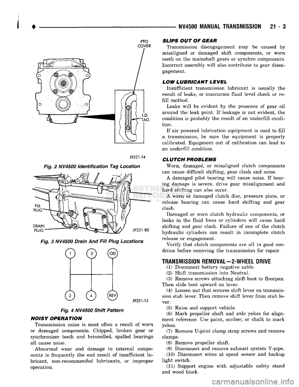
J9221-14
Fig. 2 NV4500 identification Tag Location
DRAIN
PLUG
J9221-80
Fig. 3 NV4500 Drain And Fill Plug Locations
o
0 ©
0 0©
J9221-13
Fig. 4 NV4500 Shitt Pattern
NOISY OPERATION Transmission noise is most often a result of worn
or damaged components. Chipped, broken gear or
synchronizer teeth and brinnelled, spalled bearings
all cause noise.
Abnormal wear and damage to internal compo
nents is frequently the end result of insufficient lu
bricant, non-recommended lubricants, or improper operation.
SLIPS
OUT OF
GEAR
Transmission disengagement may be caused by
misaligned or damaged shift components, or worn
teeth on the mainshaft gears or synchro components. Incorrect assembly will also contribute to gear disengagement.
LOW LUBRICANT LEWEL
Insufficient transmission lubricant is usually the
result of leaks, or inaccurate fluid level check or re
fill method.
Leaks will be evident by the presence of gear oil
around the leak point. If leakage is not evident, the
condition is probably the result of an underfill condi
tion.
If air powered lubrication equipment is used to fill
a transmission, be sure the equipment is properly
calibrated. Equipment out of calibration can lead to
an underfill condition.
CLUTCH
PROBLEMS
Worn, damaged, or misaligned clutch components
can cause difficult shifting, gear clash and noise.
A damaged pilot bearing will cause noise. If bear
ing damage is severe, drive gear misalignment and
hard shifting can also occur.
A worn or damaged clutch disc, pressure plate, or
release bearing can cause hard shifting and gear clash.
Damaged or worn clutch hydraulic components, or
leaks in the fluid lines or cylinders will cause hard shifting and gear clash. Failure of one of the clutch
hydraulic cylinders can result in incomplete clutch release or engagement.
Verify that clutch components are all in good con
dition before removing the transmission for repair.
TRANSMISSION
REMOVAL—2-WHEEL DRIVE
(1) Disconnect battery negative cable. (2) Shift transmission into Neutral.
(3) Remove screws attaching shift boot to floorpan.
Then slide boot upward on lever. (4) Loosen nut that secures shift lever on transmis
sion stub lever. Then remove shift lever from stub le
ver. (5) Raise and support vehicle.
(6) Mark propeller shaft and axle yokes for align
ment reference. Use paint, scriber, or chalk to mark
yokes.
(7) Remove U-joint clamp strap screws and remove
clamps. (8) Remove propeller shaft.
(9) Disconnect and remove exhaust system Y-pipe.
(10) Disconnect wires at speed sensor and backup
light switch. (11) Support engine with adjustable safety stand
and wood block.