1993 DODGE TRUCK wheel alignment
[x] Cancel search: wheel alignmentPage 138 of 1502
REAR
SUSPENSION
AND
AXLE
3 - 9
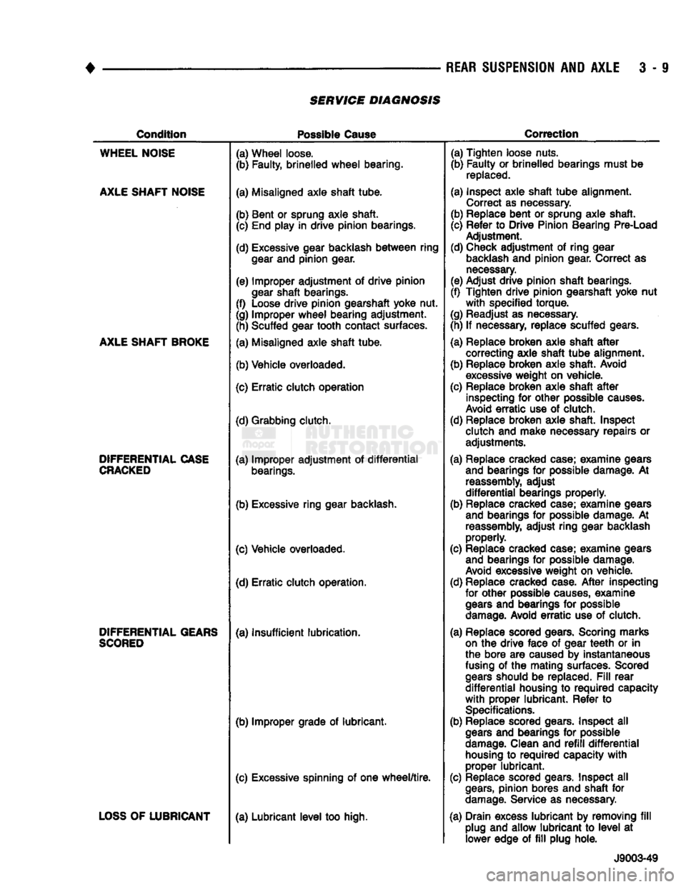
SERVICE DIAGNOSIS
Condition
Possible
Cause
Correction
WHEEL
NOISE
AXLE
SHAFT
NOISE
AXLE
SHAFT
BROKE
DIFFERENTIAL
CASE
CRACKED
DIFFERENTIAL
GEARS
SCORED
LOSS
OF
LUBRICANT
(a) Wheel loose.
(b) Faulty, brinelled
wheel
bearing.
(a) Misaligned axle shaft tube.
(b) Bent or sprung axle shaft. (c) End play in drive pinion bearings.
(d) Excessive gear backlash
between
ring
gear
and pinion gear.
(e) Improper adjustment of drive pinion
gear
shaft bearings.
(f) Loose drive pinion gearshaft yoke nut.
(g) Improper
wheel
bearing adjustment. (h) Scuffed gear tooth contact surfaces.
(a) Misaligned axle shaft tube.
(b) Vehicle overloaded.
(c) Erratic clutch operation
(d) Grabbing clutch.
(a) Improper adjustment of
differential
bearings.
(b) Excessive ring gear backlash.
(c) Vehicle overloaded. (d) Erratic clutch operation.
(a) Insufficient lubrication.
(b) Improper grade of lubricant.
(c) Excessive spinning of one
wheel/tire.
(a) Lubricant
level
too high. (a) Tighten loose nuts.
(b) Faulty or brinelled bearings must be
replaced.
(a) Inspect axle shaft
tube
alignment. Correct as necessary.
(b) Replace bent or sprung axle shaft.
(c) Refer to Drive Pinion Bearing Pre-Load Adjustment.
(d) Check adjustment of ring gear
backlash
and pinion gear. Correct as
necessary.
(e) Adjust drive pinion shaft bearings.
(f) Tighten drive pinion gearshaft yoke nut
with
specified torque.
(g) Readjust as necessary.
(h) If necessary, replace scuffed gears.
(a) Replace broken axle shaft
after
correcting axle shaft
tube
alignment.
(b) Replace broken axle shaft. Avoid
excessive
weight on vehicle.
(c) Replace broken axle shaft
after
inspecting for other possible
causes.
Avoid
erratic
use of clutch.
(d) Replace broken axle shaft. Inspect clutch and make necessary repairs or adjustments.
(a) Replace cracked case; examine gears and bearings for possible damage. At
reassembly,
adjust
differential
bearings properly.
(b) Replace cracked case; examine gears and bearings for possible damage. At
reassembly,
adjust ring gear backlash properly.
(c) Replace cracked case; examine gears and bearings for possible damage.
Avoid
excessive weight on vehicle.
(d) Replace cracked case.
After
inspecting for other possible
causes,
examine
gears
and bearings for possible
damage.
Avoid
erratic
use of clutch.
(a) Replace scored gears. Scoring marks
on
the drive face of gear
teeth
or in
the bore are caused by instantaneous
fusing
of the mating surfaces. Scored
gears
should be replaced.
Fill
rear
differential
housing to
required
capacity
with
proper lubricant. Refer to
Specifications.
(b) Replace scored gears. Inspect all
gears
and bearings for possible
damage.
Clean and
refill
differential
housing
to
required
capacity
with
proper lubricant.
(c) Replace scored gears. Inspect all
gears,
pinion bores and shaft for
damage.
Service as necessary.
(a) Drain excess lubricant by removing
fill
plug and allow lubricant to
level
at lower edge of
fill
plug hole.
J9003-49
Page 140 of 1502
•
REAR
SUSPENSION
AND
AXLE
3 - 11 8 3/8 and 9 1/4
AXLE
INDEX
page
Axle Shaft, Seal
and
Bearing Service
......... 11
Complete Axle Removal/Installation
16
Differential
Service
16
Information
11
INFORMATION
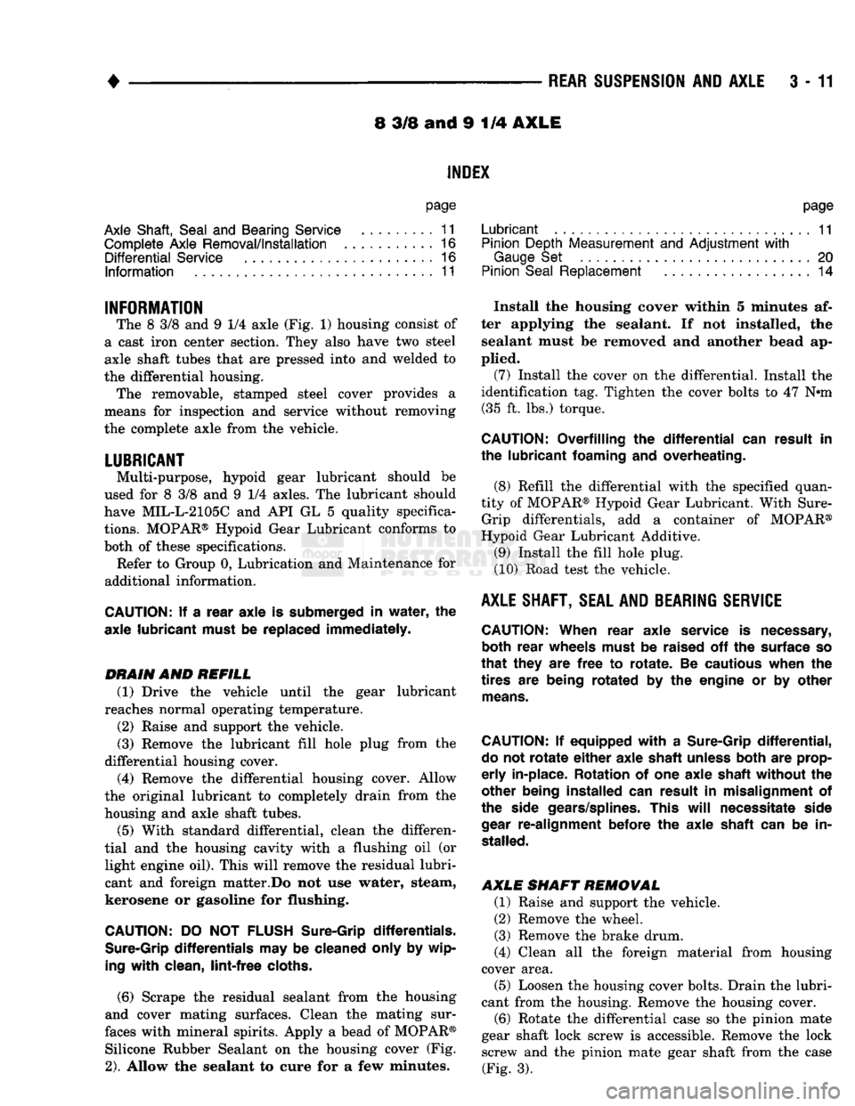
The 8 3/8 and 9 1/4 axle (Fig. 1) housing consist of
a cast iron center section. They also have two steel
axle shaft tubes that are pressed into and welded to
the differential housing. The removable, stamped steel cover provides a
means for inspection and service without removing
the complete axle from the vehicle.
LUBRICANT
Multi-purpose, hypoid gear lubricant should be
used for 8 3/8 and 9 1/4 axles. The lubricant should
have MIL-L-2105C and API GL 5 quality specifica
tions.
MOPAR® Hypoid Gear Lubricant conforms to
both of these specifications.
Refer to Group 0, Lubrication and Maintenance for
additional information.
CAUTION:
If a
rear axle
is
submerged
in
water,
the
axle lubricant must
be
replaced immediately.
DRAIN
AND
REFILL
(1) Drive the vehicle until the gear lubricant
reaches normal operating temperature.
(2) Raise and support the vehicle.
(3) Remove the lubricant fill hole plug from the
differential housing cover.
(4) Remove the differential housing cover. Allow
the original lubricant to completely drain from the
housing and axle shaft tubes. (5) With standard differential, clean the differen
tial and the housing cavity with a flushing oil (or light engine oil). This will remove the residual lubri
cant and foreign matter.Do not use water, steam,
kerosene or gasoline for flushing.
CAUTION:
DO NOT
FLUSH
Sure-Grip differentials.
Sure-Grip
differentials
may be
cleaned only
by
wip
ing
with
clean,
lint-free
cloths.
(6)
Scrape the residual sealant from the housing
and cover mating surfaces. Clean the mating sur
faces with mineral spirits. Apply a bead of MOPAR® Silicone Rubber Sealant on the housing cover (Fig.
2).
Allow the sealant to cure for a few minutes.
page
Lubricant
11
Pinion Depth Measurement
and
Adjustment
with
Gauge
Set 20
Pinion
Seal
Replacement
14
Install the housing cover within 5 minutes af
ter applying the sealant. If not installed, the sealant must be removed and another bead ap
plied. (7) Install the cover on the differential. Install the
identification tag. Tighten the cover bolts to 47 N#m (35 ft. lbs.) torque.
CAUTION:
Overfilling
the
differential
can
result
in
the lubricant foaming
and
overheating.
(8) Refill the differential with the specified quan
tity of MOPAR® Hypoid Gear Lubricant. With Sure- Grip differentials, add a container of MOPAR®
Hypoid Gear Lubricant Additive.
(9) Install the fill hole plug.
(10) Road test the vehicle.
AXLE
SHAFT, SEAL AND BEARING
SERVICE
CAUTION:
When rear axle service
is
necessary, both rear wheels must
be
raised
off the
surface
so
that
they
are
free
to
rotate.
Be
cautious when
the
tires
are
being rotated
by the
engine
or by
other
means.
CAUTION:
If
equipped
with
a
Sure-Grip
differential,
do
not
rotate
either
axle shaft unless both
are
prop
erly
in-place. Rotation
of one
axle shaft without
the
other being installed
can
result
in
misalignment
of
the side gears/splines. This
will
necessitate side
gear
re-alignment before
the
axle shaft
can be in
stalled.
AXLE SHAFT REMOVAL
(1) Raise and support the vehicle.
(2) Remove the wheel.
(3) Remove the brake drum.
(4) Clean all the foreign material from housing
cover area.
(5) Loosen the housing cover bolts. Drain the lubri
cant from the housing. Remove the housing cover.
(6)
Rotate the differential case so the pinion mate
gear shaft lock screw is accessible. Remove the lock screw and the pinion mate gear shaft from the case (Fig. 3).
Page 160 of 1502
•
REAR
SUSPENSION
AND
AXLE
3 - 33
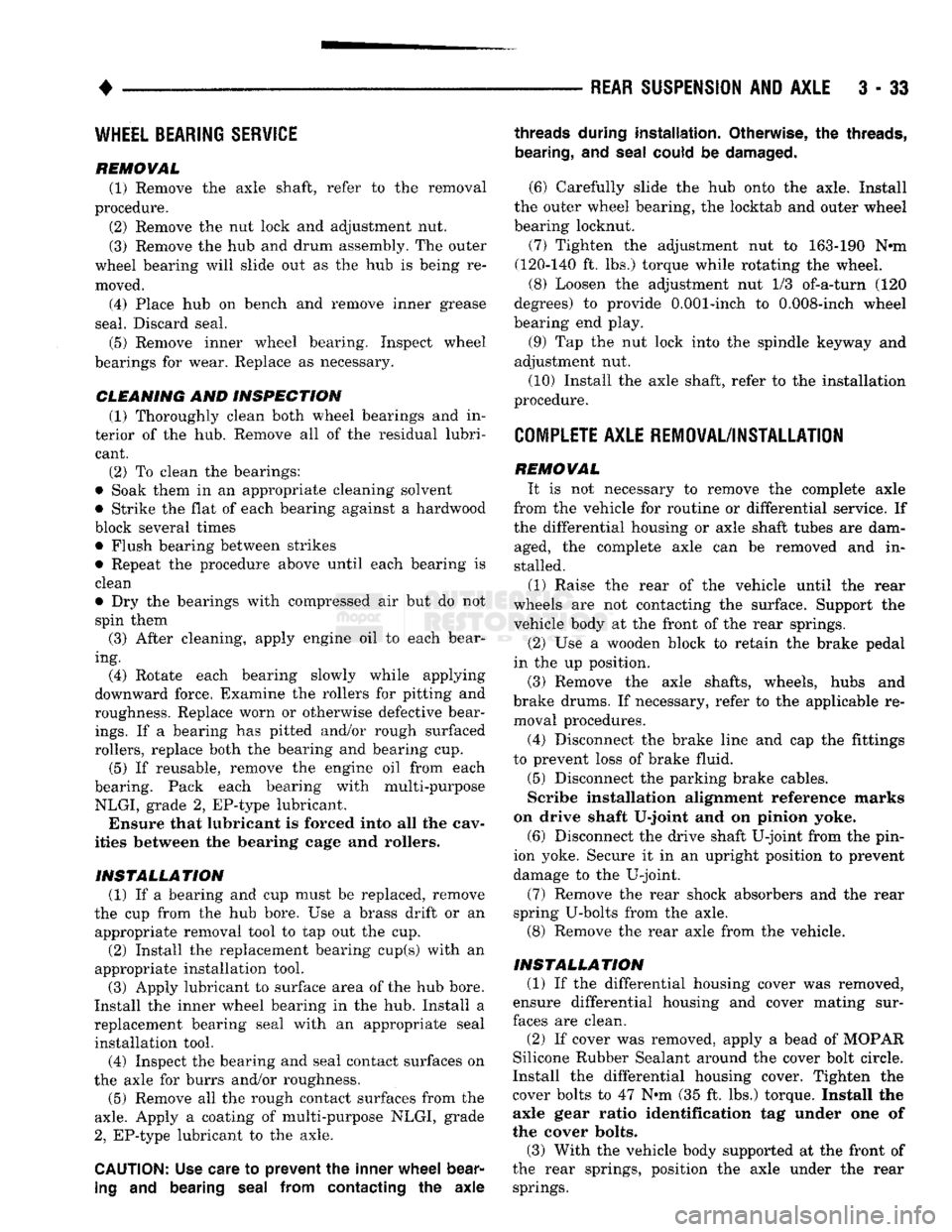
WHEEL BEARING SERVICE
REMOVAL (1) Remove the axle shaft, refer to the removal
procedure. (2) Remove the nut lock and adjustment nut.
(3) Remove the hub and drum assembly. The outer
wheel bearing will slide out as the hub is being re
moved. (4) Place hub on bench and remove inner grease
seal. Discard seal. (5) Remove inner wheel bearing. Inspect wheel
bearings for wear. Replace as necessary.
CLEANING AND INSPECTION (1) Thoroughly clean both wheel bearings and in
terior of the hub. Remove all of the residual lubri cant. (2) To clean the bearings:
• Soak them in an appropriate cleaning solvent
• Strike the flat of each bearing against a hardwood
block several times • Flush bearing between strikes
• Repeat the procedure above until each bearing is clean
• Dry the bearings with compressed air but do not
spin them (3) After cleaning, apply engine oil to each bear
ing. (4) Rotate each bearing slowly while applying
downward force. Examine the rollers for pitting and
roughness. Replace worn or otherwise defective bear
ings.
If a bearing has pitted and/or rough surfaced
rollers, replace both the bearing and bearing cup. (5) If reusable, remove the engine oil from each
bearing. Pack each bearing with multi-purpose
NLGI, grade 2, EP-type lubricant. Ensure that lubricant is forced into all the cav
ities between the bearing cage and rollers.
INSTALLATION (1) If a bearing and cup must be replaced, remove
the cup from the hub bore. Use a brass drift or an appropriate removal tool to tap out the cup. (2) Install the replacement bearing cup(s) with an
appropriate installation tool.
(3) Apply lubricant to surface area of the hub bore.
Install the inner wheel bearing in the hub. Install a
replacement bearing seal with an appropriate seal installation tool. (4) Inspect the bearing and seal contact surfaces on
the axle for burrs and/or roughness.
(5) Remove all the rough contact surfaces from the
axle.
Apply a coating of multi-purpose NLGI, grade
2,
EP-type lubricant to the axle.
CAUTION:
Use care to prevent the inner
wheel
bear
ing
and bearing
seal
from contacting the axle
threads
during installation. Otherwise, the
threads,
bearing,
and
seal
could
be
damaged.
(6) Carefully slide the hub onto the axle. Install
the outer wheel bearing, the locktab and outer wheel
bearing locknut.
(7) Tighten the adjustment nut to 163-190 Nnn
(120-140 ft. lbs.) torque while rotating the wheel. (8) Loosen the adjustment nut 1/3 of-a-turn (120
degrees) to provide 0.001-inch to 0.008-inch wheel
bearing end play.
(9) Tap the nut lock into the spindle keyway and
adjustment nut.
(10) Install the axle shaft, refer to the installation
procedure.
COMPLETE AXLE REMOVAL/INSTALLATION
REMOVAL It is not necessary to remove the complete axle
from the vehicle for routine or differential service. If
the differential housing or axle shaft tubes are dam aged, the complete axle can be removed and in
stalled.
(1) Raise the rear of the vehicle until the rear
wheels are not contacting the surface. Support the
vehicle body at the front of the rear springs.
(2) Use a wooden block to retain the brake pedal
in the up position.
(3) Remove the axle shafts, wheels, hubs and
brake drums. If necessary, refer to the applicable re moval procedures.
(4) Disconnect the brake line and cap the fittings
to prevent loss of brake fluid. (5) Disconnect the parking brake cables.
Scribe installation alignment reference marks
on drive shaft U-joint and on pinion yoke. (6) Disconnect the drive shaft U-joint from the pin
ion yoke. Secure it in an upright position to prevent
damage to the U-joint.
(7) Remove the rear shock absorbers and the rear
spring U-bolts from the axle. (8) Remove the rear axle from the vehicle.
INSTALLATION (1) If the differential housing cover was removed,
ensure differential housing and cover mating sur
faces are clean.
(2) If cover was removed, apply a bead of MOPAR
Silicone Rubber Sealant around the cover bolt circle.
Install the differential housing cover. Tighten the
cover bolts to 47 N»m (35 ft. lbs.) torque. Install the axle gear ratio identification tag under one of
the cover bolts.
(3) With the vehicle body supported at the front of
the rear springs, position the axle under the rear springs.
Page 233 of 1502
i - 46
BRAKES
• DRUM
BRAKES—ELEVEN
INCH
INDEX
page
Brake Drum Inspection
and
Refinishing
........ 48
Brake Drum
Installation
.................... 48
Brake Drum Removal
46
Brake
Shoe
Installation
. 47
Brake Support
Plate
Installation
49
Brake Support
Plate
Removal
............... 49
page
Brakeshoe Removal
...................... 46
Cleaning
and
Inspection
47
General
Information
46
Wheel Cylinder
Installation
50
Wheel Cylinder Overhaul
49
Wheel Cylinder Removal
49
GENERAL
INFORMATION
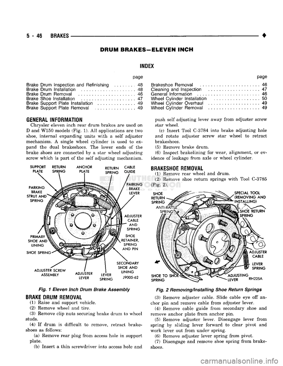
Chrysler eleven inch rear drum brakes are used on
D and W150 models (Fig. 1). All applications are two
shoe,
internal expanding units with a self adjuster
mechanism. A single wheel cylinder is used to ex
pand the dual brakeshoes. The lower ends of the
brake shoes are connected by a star wheel adjusting screw which is part of the self adjusting mechanism.
SUPPORT PLATE PARKING
BRAKE
STRUT
AND
SPRING RETURN
SPRING ANCHOR
PLATE RETURN CABLE
SPRING GUJDE
PRIMARY
SHOE
AND
LINING
SHOE SPRING
ADJUSTER SCREW
ASSEMBLY
ADJUSTER
LEVER LEVER
SPRING PARKING
BRAKE
LEVER
ADJUSTER CABLE AND
SPRING
SHOE
RETAINER, SPRING
AND
PIN
SECONDARY SHOE
AND
LINING
J9005-62
Fig.
1 Eleven
Inch
Drum
Brake
Assembly
BRAKE
DRUM REMOVAL
(1) Raise and support vehicle. (2) Remove wheel and tire.
(3) Remove clip nuts securing brake drum to wheel
studs.
(4) If drum is difficult to remove, retract brake-
shoes as follows: (a) Remove rear plug from access hole in support
plate. (b) Insert a thin screwdriver into access hole and push self adjusting lever away from adjuster screw
star wheel. (c) Insert Tool C-3784 into brake adjusting hole
and rotate adjuster screw star wheel to retract
brakeshoes.
(5) Remove brake drum.
(6) Inspect brakelining for wear, alignment, or ev
idence of leakage from axle or wheel cylinder.
BRAKESHOE
REMOVAL
(1) Remove rear wheel and drum.
(2) Remove shoe return springs with Tool C-3785
(Fig. 2).
SHOE
RETURN SPRING SPECIAL
TOOL
(REMOVING
AND
INSTALLING)
SHOE
TO SHOE
SPRING LEVER
SPRING
ADJUSTING
LEVER
RH225A
Fig.
2 Removing/Installing
Shoe
Return
Springs
(3) Remove adjuster cable. Slide cable eye off an
chor pin and remove cable from adjuster lever.
(4) Remove cable guide from secondary shoe and
remove anchor plate from anchor pin. (5) Remove adjuster lever. Disengage lever from
spring by sliding lever forward to clear pivot and
work lever out from under spring.
(6) Remove adjuster lever spring from pivot.
(7) Disengage and remove shoe spring from brake-
shoes.
Page 239 of 1502
5
- 52
BRAKES
•
BRAKE
DRUM
REMOVAL
(1) Raise and support vehicle.
(2) Remove wheel and tire assembly.
(3) Remove axle shaft nuts, washers and cones.
Strike axle shaft in center with copper or dead blow
hammer to loosen retaining cones.
(4) Remove axle shaft.
(5) Remove outer hub nut.
(6)
Straighten and remove lock washer.
(7) Remove inner nut and bearing.
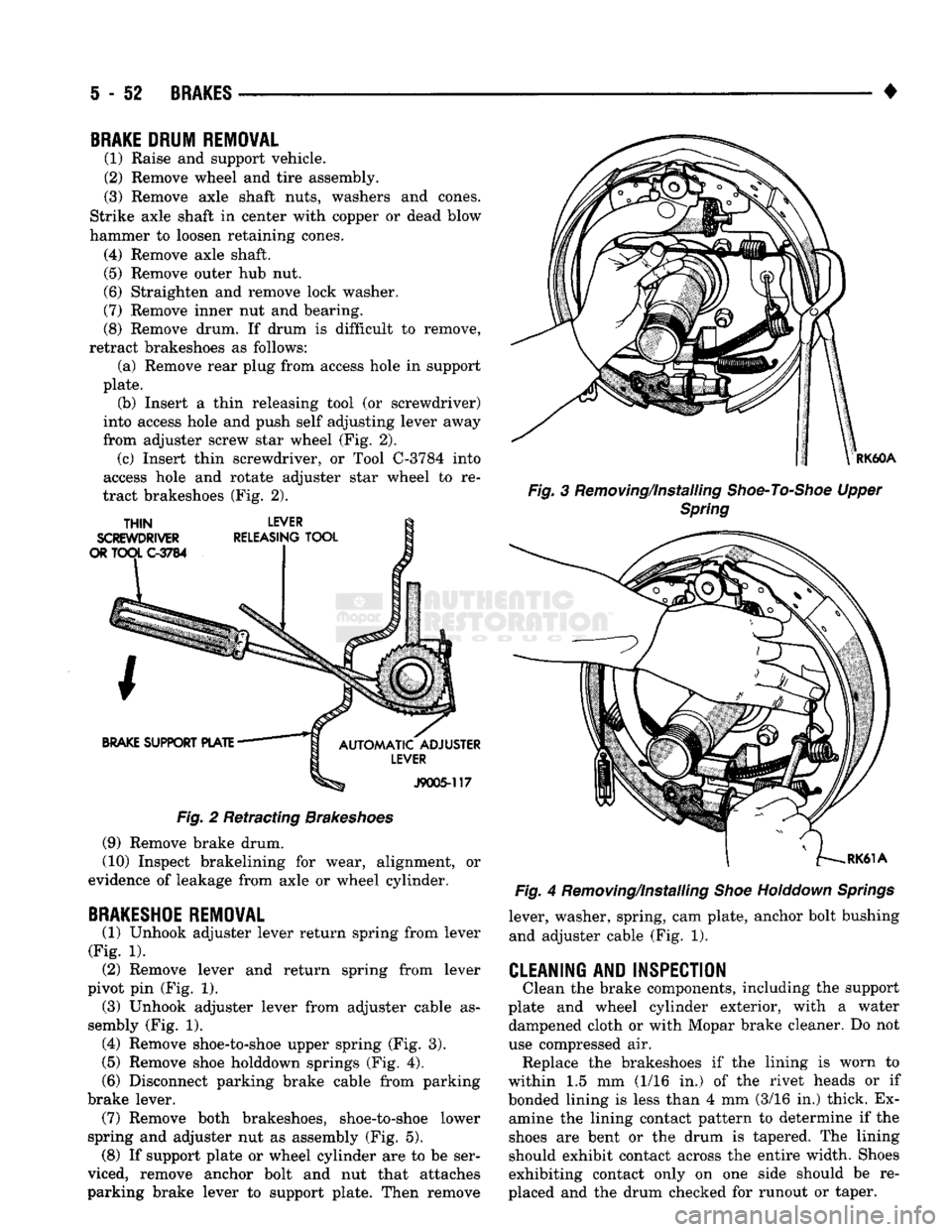
(8) Remove drum. If drum is difficult to remove,
retract brakeshoes as follows: (a) Remove rear plug from access hole in support
plate. (b) Insert a thin releasing tool (or screwdriver)
into access hole and push self adjusting lever away
from adjuster screw star wheel (Fig. 2). (c) Insert thin screwdriver, or Tool C-3784 into
access hole and rotate adjuster star wheel to re
tract brakeshoes (Fig. 2).
Fig.
2 Retracting
Brakeshoes
(9) Remove brake drum.
(10) Inspect brakelining for wear, alignment, or
evidence of leakage from axle or wheel cylinder.
BRAKESHOE
REMOVAL
(1) Unhook adjuster lever return spring from lever
(Fig. 1). (2) Remove lever and return spring from lever
pivot pin (Fig. 1). (3) Unhook adjuster lever from adjuster cable as
sembly (Fig. 1). (4) Remove shoe-to-shoe upper spring (Fig. 3).
(5)
Remove shoe holddown springs (Fig. 4).
(6)
Disconnect parking brake cable from parking
brake lever. (7) Remove both brakeshoes, shoe-to-shoe lower
spring and adjuster nut as assembly (Fig. 5). (8) If support plate or wheel cylinder are to be ser
viced, remove anchor bolt and nut that attaches
parking brake lever to support plate. Then remove
RK60A
Fig.
3 Removing/Installing
Shoe-To-Shoe
Upper
Spring
Fig.
4 Removing/Installing
Shoe
Holddown
Springs
lever, washer, spring, cam plate, anchor bolt bushing and adjuster cable (Fig. 1).
CLEANING AND INSPECTION
Clean the brake components, including the support
plate and wheel cylinder exterior, with a water dampened cloth or with Mopar brake cleaner. Do not
use compressed air. Replace the brakeshoes if the lining is worn to
within 1.5 mm (1/16 in.) of the rivet heads or if
bonded lining is less than 4 mm (3/16 in.) thick. Ex amine the lining contact pattern to determine if the
shoes are bent or the drum is tapered. The lining
should exhibit contact across the entire width. Shoes
exhibiting contact only on one side should be re
placed and the drum checked for runout or taper.
Page 255 of 1502
6
- 2
CLUTCH
•
CLUTCH DIAGNOSIS
INDEX
page
Clutch Problem
Causes
, 2
General
Diagnosis
Information
2
GENERAL
DIAGNOSIS INFORMATION
Unless the cause of a clutch problem is obvious, a
road test and component inspection will be required
for accurate diagnosis. A road test will help determine the type of fault
while component inspection will identify the problem component. During a road test, drive the vehicle at normal
speeds. Shift the transmission through all gear
ranges and observe clutch action. If chatter, grab, slip, or improper release is experi
enced, remove and inspect the clutch components.
However, if the problem is noise or hard shifting,
further diagnosis is needed. The transmission or an
other driveline component may actually be at fault. Careful observation during a road test will help
narrow the problem area.
CLUTCH PROBLEM
CAUSES
CONTAMINATION Fluid contamination is one of the more common
causes of clutch malfunctions. Oil, water, or clutch
fluid on the clutch contact surfaces will result in
faulty operation. The usual result is chatter, slip, or
grab.
During inspection, note if any components are con
taminated with oil, hydraulic fluid, or water/road splash.
Oil contamination indicates a leak at either the
rear main seal or transmission input shaft.
Oil leakage produces a residue of oil on the hous
ing interior and on the clutch cover and flywheel.
Heat buildup caused by slippage between the cover,
disc and flywheel, can sometimes bake the oil residue
onto the components. The glaze-like residue ranges
in color from amber to black.
Road splash contamination means dirt and water
are entering the clutch housing due to loose bolts,
housing cracks, vent openings, or through the slave
cylinder opening. Driving through deep water pud
dles can force water/road splash into the housing
through such openings.
An additional problem caused by water contamina
tion and especially by steam cleaning, involves
clutch disc sticking and poor release. Water and steam vapors can be absorbed by the
clutch facing material. If the vehicle sits idle for long
page
Inspection
and
Diagnosis
Charts 5
periods after water contamination, the force exerted
by the pressure plate may cause the disc to bond it self to the flywheel or pressure plate.
Frequently, the only remedy for the above condi
tion is component replacement. To avoid this prob
lem, a vehicle should be driven as soon as possible to
heat and dry the clutch components.
Clutch fluid leaks are from a loose or damaged
slave cylinder line or connection. However, clutch
fluid leaks will usually be noted and corrected before severe contamination occurs.
CLUTCH MISALIGNMENT
Clutch components must be in proper alignment
with the crankshaft and transmission input shaft.
Misalignment caused by excessive runout or warpage of any clutch component will cause grab, chatter and improper clutch release.
Flywheel
Runout
Common causes of runout are heat warping, im
proper machining, mounting the flywheel on a dirty crankshaft flange, incorrect bolt tightening, or im
proper seating on the crankshaft flange shoulder.
Very light scratches or surface roughness on the
flywheel face can be cleaned up by scuff sanding with 180 grit emery cloth. However, if the surface is
warped or severely scored, replace the flywheel.
Do not machine the flywheel. The flywheel
face is manufactured with a unique surface con
tour. Machining would negate this feature and could result in unsatisfactory operation.
Clean the crankshaft flange before mounting the
flywheel. Dirt and grease on the flange surface may cock the flywheel causing runout.
Use new bolts when remounting a flywheel and se
cure the bolts with Mopar Lock And Seal, or Loctite
242.
Tighten flywheel bolts to specified torque only.
Overtightening could distort the flywheel hub caus
ing runout.
Clutch
Cover
And Disc
Runout
Check the clutch disc before installation. Axial
(face) runout of a new disc should not exceed 0.5 mm
(0.020 in.). Measure runout about 6 mm (1/4 in.)
from the outer edge of the disc facing. Obtain an other disc if runout is excessive.
Page 256 of 1502
•
CLUTCH
6 - 3 Check condition of the clutch before installation. A
warped cover or diaphragm spring will cause grab and incomplete release or engagement.
Be careful when handling the cover and disc. Im
pact can distort the cover, diaphragm spring, release
fingers and the hub of the clutch disc.
Use an alignment tool when positioning the disc on
the flywheel. The tool prevents accidental misalign ment which could result in cover distortion and disc
damage.
A frequent cause of clutch cover distortion (and
consequent misalignment) is improper bolt tighten
ing. To avoid warping the cover, tighten the bolts al
ternately (in a diagonal pattern) and evenly (2-3
threads at a time) to specified torque.
Clutch
Housing
Misalignment And Runout Clutch housing alignment is important to proper
operation. The housing bore maintains alignment be
tween the crankshaft and transmission input shaft.
Misalignment can cause noise, incomplete clutch
release and chatter. It can also result in premature
wear of the pilot bearing, cover release fingers and
clutch disc. In severe cases, misalignment can also cause premature wear of the transmission input
shaft and bearing.
Housing face misalignment is generally caused by
incorrect seating on the engine or transmission, loose
housing bolts, missing alignment dowels or housing damage. Infrequently, misalignment may also be
caused by housing mounting surfaces that are not
parallel. If housing misalignment is suspected, housing bore
and face runout can be checked with a dial indicator
as described in the following two procedures:
MEASURING
CLUTCH HOUSING BORE
RUNOUT
(1) Remove the clutch housing and strut.
(2) Remove the clutch cover and disc.
(3) Replace one of the flywheel bolts with a 7/16-20
threaded rod that is 10 in. (25.4 cm) long (Fig. 1).
The rod will be used to mount the dial indicator.
(4) Remove the release fork from the clutch hous
ing. (5) Reinstall the clutch housing. Tighten the hous
ing bolts nearest the alignment dowels first. (6) Mount the dial indicator on the threaded rod
and position the indicator plunger on the surface of
the clutch housing bore (Fig. 2).
(7) Rotate the crankshaft until the indicator
plunger is at the top center of the housing bore. Zero the indicator at this point.
(8) Rotate the crankshaft and record the indicator
readings at eight points (45° apart) around the bore (Fig. 3). Repeat the measurement at least twice for
accuracy. (9) Subtract each reading from the one 180° oppo
site to determine magnitude and direction of runout.
Refer to Figure 3 and following example.
Bore runout example: 0.000 - (-0.007) = 0.007 in. + 0.002 - (-0.010) = 0.012 in.
+ 0.004 - (-0.005) = 0.009 in.
-0.001 -
(
+ 0.001) = -0.002 in. (= 0.002 inch)
In the above example, the largest difference is
0.012 in. and is called the total indicator reading
(TIR).
This means that the housing bore is offset
from the crankshaft centerline by 0.006 in. (which is 1/2 of 0.012 in.).
On gas engines, the acceptable maximum TIR for
housing bore runout is 0.010 inch. If measured TIR is more than 0.010 in. (as in the example), bore runout
will have to be corrected with offset dowels. Offset dowels are available in 0.007, 0.014 and 0.021 in.
sizes for this purpose (Fig. 4). Refer to Correcting
Housing Bore Runout for dowel installation.
On diesel engines, the acceptable maximum
TIR for housing bore runout is 0.015 inch. How
ever, unlike gas engines, offset dowels are not available to correct runout on diesel engines. If
bore runout exceeds the stated maximum on a diesel engine, it may be necessary to replace ei
ther the clutch housing, or transmission adapter
plate.
CORRECTING CLUTCH HOUSING BORE
RUNOUT
(GAS
ENGINE
ONLY)
On gas engine vehicles, clutch housing bore runout
is corrected with offset dowels. However, if bore
runout exceeds 0.015 in. TIR on a diesel equipped model, the clutch housing, or transmission adapter
plate may have to be replaced. Offset dowels are not available for diesel models.
The dial indicator reads positive when the plunger
moves inward (toward indicator) and negative when it moves outward (away from indicator). As a result,
the lowest or most negative reading determines the
direction of housing bore offset (runout).
In the sample readings shown in Figure 3 and in
step (7) above, the bore is offset toward the 0.010
inch reading. To correct this, remove the housing and
original dowels. Then install the new offset dowels in
the direction needed to center the bore with the crankshaft centerline.
In the example, TIR was 0.012 inch. The dowels
needed for correction would have an offset of 0.007
in. (Fig. 4).
Install the dowels with the slotted side facing out
so they can be turned with a screwdriver. Then in
stall the housing, remount the dial indicator and
check bore runout again. Rotate the dowels until the
TIR is less than 0.010 in. if necessary.
If a TIR of 0.053 in. or greater is encountered, it
may be necessary to replace the clutch housing.
Page 258 of 1502

•
CLUTCH
6 - 5
INDICATOR
PLUNGER
DIAL INDICATOR
CLUTCH
HOUSING
FACE
INDICATOR MOUNTING
„
STUD OR ROD
J9006-29
Fig.
5
Measuring
Clutch
Housing
Face
Runout
+
.009 CLUTCH
HOUSING
FACE
CIRCLE
(AT RIM
OF BORE)
,004
(SAMPLE
READINGS)
J9006-30
Fig.
6
Housing
Face Measurement
Points
And
Sample
Readings
INSTALLATION
METHODS
AND
PARTS
USAGE
Distortion of clutch components during installation
and the use of non-standard components are addi
tional causes of clutch malfunction.
Improper clutch cover bolt tightening can distort
the cover. The usual result is clutch grab, chatter
CUT/DRILL
BOLT
HOLE
TO SIZE SHIM
STOCK
MAKE
SHIM
1-INCH
DIAMETER
J9006-31
Fig.
7
Housing
Face
Alignment
Shims
and rapid wear. Tighten the cover bolts as described
in the Clutch Service section.
Improperly seated flywheels and clutch housings
are other causes of clutch failure. Improper seating
will produce misalignment and subsequent clutch problems.
Tighten the clutch housing bolts to proper torque
before installing any struts. Also be sure the align ment dowels are in place and seated in the block and
housing beforehand.
The use of non-standard or low quality parts can
also lead to problems and wear. Use the recom
mended factory quality parts to avoid comebacks.
INSPECTION AND DIAGNOSIS CHARTS
The clutch inspection chart (Fig. 8) outlines items
to be checked before and during clutch installation. Use the chart as a check list to help avoid overlooking potential problem sources during service opera
tions.
The diagnosis charts describe common clutch prob
lems,
causes and correction. Fault conditions are
listed at the top of each chart. Conditions, causes and
corrective action are outlined in the indicated col
umns.
The charts are provided as a convenient reference
when diagnosing faulty clutch operation.