1993 DODGE TRUCK spark plugs
[x] Cancel search: spark plugsPage 863 of 1502
14 - 44
FUEL
SYSTEM
•
Fig.
4 ignition Coil—5.9L
HDC-Gas
Engine
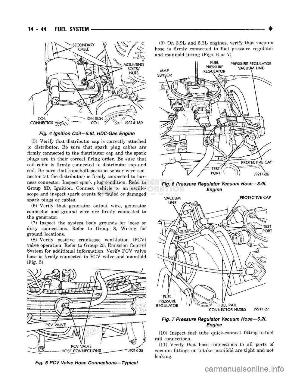
(5) Verify that distributor cap is correctly attached
to distributor. Be sure that spark plug cables are
firmly connected to the distributor cap and the spark
plugs are in their correct firing order. Be sure that coil cable is firmly connected to distributor cap and
coil. Be sure that camshaft position sensor wire con
nector (at the distributor) is firmly connected to har
ness connector. Inspect spark plug condition. Refer to Group 8D, Ignition. Connect vehicle to an oscillo
scope and inspect spark events for fouled or damaged
spark plugs or cables.
(6) Verify that generator output wire, generator
connector and ground wire are firmly connected to
the generator. (7) Inspect the system body grounds for loose or
dirty connections. Refer to Group 8, Wiring for
ground locations. (8) Verify positive crankcase ventilation (PCV)
valve operation. Refer to Group 25, Emission Control System for additional information. Verify PCV valve
hose is firmly connected to PCV valve and manifold (Fig. 5).
Fig.
5 PCV
Valve
Hose
Connections—Typical (9) On 3.9L and 5.2L engines, verify that vacuum
hose is firmly connected to fuel pressure regulator and manifold fitting (Figs. 6 or 7).
CONNECTOR
HOSES
J9214-27
Fig.
7
Pressure
Regulator
Vacuum
Hose—5.2L
Engine
(10) Inspect fuel* tube quick-connect fitting-to-fuel
rail connections. (11) Verify that hose connections to all ports of
vacuum fittings on intake manifold are tight and not leaking.
Page 877 of 1502
14 - 58
FUEL
SYSTEM
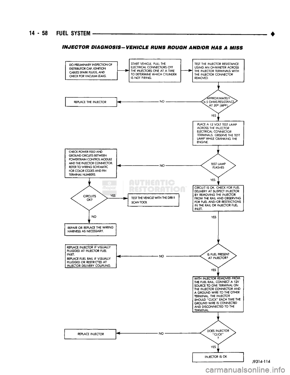
• INJECTOR DIAGNOSIS-VEHICLE RUNS ROUGH AND/OR HAS A
MISS
DO PRELIMINARY INSPECTION OF DISTRIBUTOR CAP,
IGNITION
CABLES
SPARK
PLUGS,
AND
CHECK
FOR VACUUM
LEAKS.
START VEHICLE, PULL THE
ELECTRICAL
CONNECTORS OFF
THE INJECTORS ONE AT A TIME
TO DETERMINE
WHICH
CYLINDER
IS
NOT FIRING.
REPLACE
THE INJECTOR -NO •
CHECK
POWER FEED AND
GROUND CIRCUITS BETWEEN POWERTRAIN CONTROL MODULE
AND THE INJECTOR CONNECTOR.
REFER
TO WIRING SCHEMATIC
FOR COLOR CODES AND PIN
TERMINAL NUMBERS. - NO-
YES
TEST THE VEHICLE
WITH
THE DRB II
SCAN
TOOL
NO
REPAIR
OR REPLACE THE WIRING
HARNESS
AS NECESSARY.
REPLACE
INJECTOR IF VISUALLY
PLUGGED
AT INJECTOR FUEL INLET.
REPLACE
FUEL RAIL IF VISUALLY
PLUGGED
OR RESTRICTED AT INJECTOR DELIVERY COUPLING. -NO
REPLACE
INJECTOR •NO-TEST THE INJECTOR RESISTANCE
USING AN OHMMETER
ACROSS
THE INJECTOR TERMINALS
WITH
THE INJECTOR CONNECTOR
REMOVED.
PLACE
A 12
VOLT
TEST LAMP
ACROSS
THE INJECTOR
ELECTRICAL
CONNECTOR
TERMINALS.
OBSERVE THE TEST LAMP WHILE CRANKING THE
ENGINE.
CIRCUIT IS OK. CHECK FOR FUEL DELIVERY AT SUSPECT INJECTOR
BY
REMOVING THE INJECTOR FROM THE RAIL AND OBSERVING
FOR FUEL AND/OR RESTRICTIONS IN THE RAIL OR INJECTOR FUEL INLET.
WITH
INJECTOR REMOVED FROM
THE FUEL RAIL, CONNECT A 12V
SOURCE
TO ONE TERMINAL ON
THE INJECTOR CONNECTOR AND
A
GROUND WIRE TO THE OTHER
TERMINAL. THE INJECTOR SHOULD "CLICK" EACH TIME THE GROUND WIRE IS CONNECTED
AND DISCONNECTED TO THE TERMINAL.
J9314-114
Page 878 of 1502
•
FUEL SYSTEM
14 - 59
fill
DHADn
HIAf5MflCTipQ
/f|Rn
The powertrain control module (PCM) has been
programmed to monitor many different circuits of the
fuel injection system. If a problem is sensed in a monitored circuit often enough to indicate an actual
problem, a diagnostic trouble code (DTC) is stored.
The DTC will be stored in the PCM memory for eventual display to the service technician. If the
problem is repaired or ceases to exist, the PCM can cels the DTC after 51 engine starts.
Certain criteria must be met for a diagnostic trou
ble code (DTC) to be entered into PCM memory. The criteria may be a specific range of engine rpm, en
gine temperature and/or input voltage to the PCM.
It is possible that a DTC for a monitored circuit
may not be entered into memory even though a mal
function has occurred. This may happen because one
of the DTC criteria for the circuit has not been met. Example: assume that one of the criteria for the
MAP sensor circuit is that the engine must be oper ating between 750 and 2000 rpm to be monitored for
a DTC. If the MAP sensor output circuit shorts to
ground when the engine rpm is above 2400 rpm, a 0
volt input will be seen by the PCM. A DTC will not
be entered into memory because the condition does not occur within the specified rpm range.
A DTC indicates that the powertrain control mod
ule (PCM) has recognized an abnormal signal in a
circuit or the system. A DTC may indicate the result
of a failure, but never identify the failed component
directly.
There are several operating conditions that the
PCM does not monitor and set a DTC for. Refer to
the following Monitored Circuits and Non-Monitored Circuits in this section.
MONITORED
CIRCUITS
The powertrain control module (PCM) can detect
certain problems in the fuel injection system.
Open or Shorted Circuit - The PCM can deter
mine if sensor output (which is the input to PCM) is
within proper range. It also determines if the circuit is open or shorted.
Output Device Current Flow - The PCM senses
whether the output devices are hooked up.
If there is a problem with the circuit, the PCM
senses whether the circuit is open, shorted to ground
(-), or shorted to
(
+
)
voltage.
Oxygen Sensor - The PCM can determine if the
oxygen sensor is switching between rich and lean.
This is, once the system has entered Closed Loop. Re fer to Open Loop/Closed Loop Modes Of Operation in
the Component Description/System Operation section
for an explanation of Closed (or Open) Loop opera tion.
NON-MONITORED CIRCUITS
The PCM does not monitor the following circuits,
systems or conditions that could have malfunctions
that result in driveability problems. A diagnostic trouble code (DTC) may not be displayed for these
conditions.
Fuel Pressure: Fuel pressure is controlled by the
vacuum assisted fuel pressure regulator. The PCM
cannot detect a clogged fuel pump inlet filter, clogged
in-line fuel filter, or a pinched fuel supply or return
line.
However, these could result in a rich or lean
condition causing an oxygen sensor DTC to be stored in the PCM.
Secondary Ignition Circuit: The PCM cannot de
tect an inoperative ignition coil, fouled or worn spark
plugs,
ignition cross firing, or open circuited spark
plug cables.
Engine Timing: The PCM cannot detect an incor
rectly indexed timing chain, camshaft sprocket or crankshaft sprocket. The PCM also cannot detect an
incorrectly indexed distributor. However, these could
result in a rich or lean condition causing an oxygen
sensor DTC to be stored in the PCM.
Cylinder Compression: The PCM cannot detect
uneven, low, or high engine cylinder compression.
Exhaust System: The PCM cannot detect
a
plugged, restricted or leaking exhaust system.
Fuel Injector Malfunctions: The PCM cannot de
termine if the fuel injector is clogged, or the wrong injector is installed. However, these could result in a
rich or lean condition causing an oxygen sensor DTC
to be stored in the PCM.
Excessive Oil Consumption: Although the PCM
monitors exhaust stream oxygen content through ox
ygen sensor (closed loop), it cannot determine exces sive oil consumption.
Throttle Body Air Flow: The PCM cannot detect
a clogged or restricted air cleaner inlet or air filter
element.
Evaporative System: The PCM will not detect a
restricted, plugged or loaded EVAP canister. Vacuum Assist: Leaks or restrictions in the vac
uum circuits of vacuum assisted engine control sys
tem devices are not monitored by the PCM. However, a vacuum leak at the MAP sensor will be monitored
and a diagnostic trouble code (DTC) will be gener
ated by the PCM.
Powertrain Control Module (PCM) System
Ground: The PCM cannot determine a poor system
ground. However, a DTC may be generated as a re
sult of this condition.
Powertrain Control Module (PCM) Connector
Engagement: The PCM cannot determine spread or
damaged connector pins. However, a DTC may be generated as a result of this condition.
Page 1479 of 1502
25
- 2
EMISSION
CONTROL
SYSTEMS
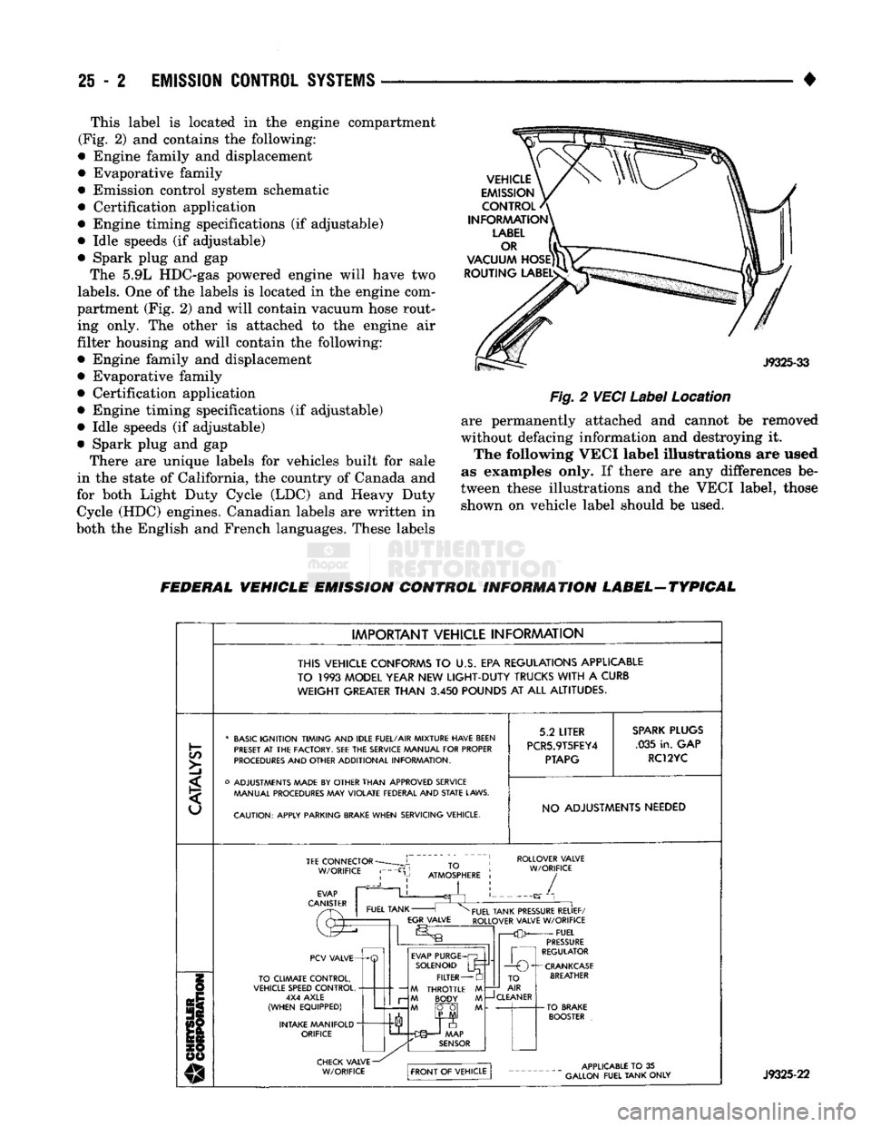
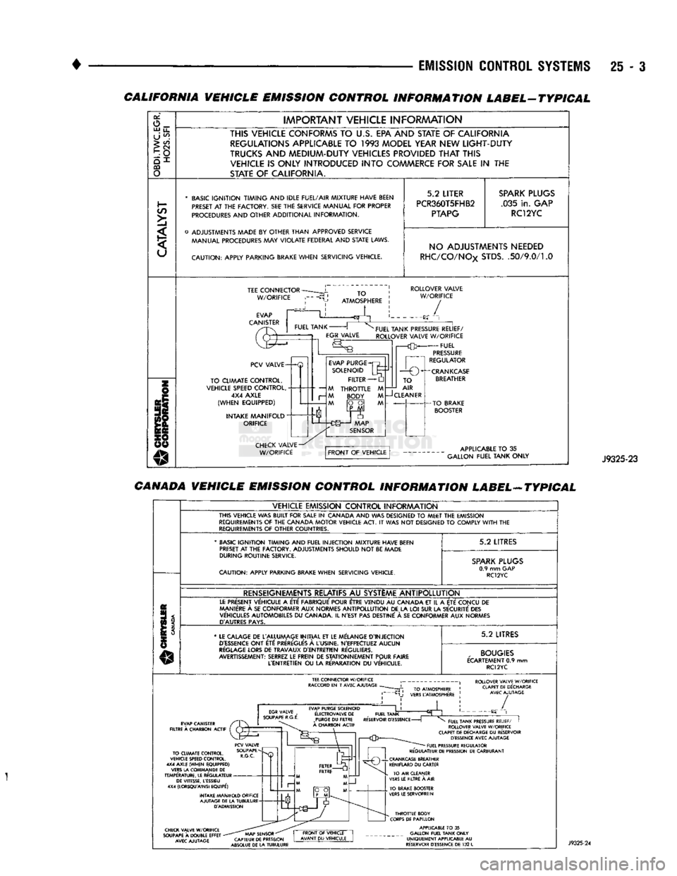
• This label is located in the engine compartment
(Fig. 2) and contains the following:
• Engine family and displacement
• Evaporative family
• Emission control system schematic
• Certification application
• Engine timing specifications (if adjustable)
• Idle speeds (if adjustable)
• Spark plug and gap The 5.9L HDC-gas powered engine will have two
labels.
One of the labels is located in the engine com
partment (Fig. 2) and will contain vacuum hose rout ing only. The other is attached to the engine air
filter housing and will contain the following:
• Engine family and displacement
• Evaporative family
• Certification application
• Engine timing specifications (if adjustable)
• Idle speeds (if adjustable)
• Spark plug and gap There are unique labels for vehicles built for sale
in the state of California, the country of Canada and
for both Light Duty Cycle (LDC) and Heavy Duty Cycle (HDC) engines. Canadian labels are written in
both the English and French languages. These labels
Fig.
2
VECI
Label
Location
are permanently attached and cannot be removed
without defacing information and destroying it. The following VECI label illustrations are used
as examples only. If there are any differences be
tween these illustrations and the VECI label, those shown on vehicle label should be used.
FEDERAL VEHICLE EMISSION CONTROL INFORMATION LABEL-TYPICAL
IMPORTANT VEHICLE INFORMATION
THIS VEHICLE CONFORMS
TO U.S. EPA
REGULATIONS APPLICABLE
TO
1993
MODEL YEAR
NEW
LIGHT-DUTY
TRUCKS
WITH
A
CURB
WEIGHT
GREATER
THAN
3.450
POUNDS
AT ALL
ALTITUDES.
C/5
>]
* BASIC IGNITION TIMING AND IDLE FUEL/AIR MIXTURE HAVE BEEN
PRESET
AT THE
FACTORY.
SEE THE
SERVICE MANUAL FOR PROPER
PROCEDURES AND OTHER ADDITIONAL INFORMATION.
o ADJUSTMENTS MADE
BY
OTHER THAN APPROVED SERVICE MANUAL PROCEDURES
MAY
VIOLATE FEDERAL AND
STATE
LAWS.
CAUTION: APPLY PARKING
BRAKE
WHEN SERVICING VEHICLE. 5.2
LITER
PCR5.9T5FEY4
PTAPG
SPARK
PLUGS
.035 in. GAP
RC12YC
NO ADJUSTMENTS NEEDED TEE
CONNECTOR
W/ORIFICE ROLLOVER VALVE
W/ORIFICE
PCV VALVE-
TO CLIMATE CONTROL,
VEHICLE SPEED CONTROL, 4X4 AXLE
(WHEN EQUIPPED)
INTAKE MANIFOLD
"
ORIFICE EVAP PURGE
SOLENOID FILTER
M THROTTLE M M BODY M
M fO~0| M TO
AIR
—J
CLEANER
-CRANKCASE
BREATHER J9325-22
Page 1480 of 1502
EMISSION
CONTROL SYSTEMS
25 - :
CALIFORNIA VEHICLE EMISSION CONTROL INFORMATION LABEL-TYPICAL
or,
o_ UJ
u_
U
^
>
CO
CQ
o
IMPORTANT
VEHICLE
INFORAAATION
THIS VEHICLE CONFORMS
TO
U.S.
EPA AND STATE
OF
CALIFORNIA REGULATIONS APPLICABLE
TO 1993
MODEL YEAR NEW
LIGHT-DUTY
TRUCKS
AND
MEDIUM-DUTY VEHICLES PROVIDED
THAT
THIS VEHICLE
IS
ONLY INTRODUCED
INTO
COMMERCE FOR
SALE
IN THE
STATE
OF
CALIFORNIA.
*
BASIC
IGNITION TIMING
AND
IDLE FUEL/AIR
MIXTURE HAVE BEEN
PRESET
AT THE
FACTORY.
SEE THE
SERVICE MANUAL
FOR
PROPER
PROCEDURES
AND
OTHER
ADDITIONAL
INFORMATION.
o
ADJUSTMENTS MADE
BY
OTHER
THAN
APPROVED
SERVICE MANUAL PROCEDURES
MAY
VIOLATE
FEDERAL
AND
STATE
LAWS.
CAUTION:
APPLY
PARKING BRAKE
WHEN
SERVICING
VEHICLE.
5.2
LITER
PCR360T5FHB2
PTAPG
SPARK
PLUGS
.035
in.
GAP RC12YC NO ADJUSTMENTS NEEDED
RHC/CO/NOx
STDS.
.50/9.0/1.0
TEE
CONNECTOR
W/ORIFICE
TO
ATMOSPHERE
ROLLOVER
VALVE
W/ORIFICE
/
PCV
VALVE-
TO
CLIMATE
CONTROL,
VEHICLE SPEED
CONTROL,
4X4
AXLE
(WHEN
EQUIPPED)
INTAKE
MANIFOLD"
ORIFICE
—
M
r-
M
EVAP
PURGE
SOLENOID
FILTER
THROTTLE
BODY
FUEL
TANK PRESSURE
RELIEF/
ROLLOVER
VALVE
W/ORIFICE
FUEL
PRESSURE
REGULATOR
1
r—O
O^-CRANKCASE
TO
AIR
CLEANER
APPLICABLE
TO
35
GALLON
FUEL
TANK
ONLY
J9325-23
CANADA VEHICLE EMISSION CONTROL INFORMATION LABEL-ATYPICAL
VEHICLE
EMISSION
CONTROL
INFORAAATION
THIS
VEHICLE
WAS
BUILT
FOR
SALE
IN
CANADA
AND WAS
DESIGNED
TO
MEET
THE
EMISSION
REQUIREMENTS
OF THE
CANADA
MOTOR
VEHICLE
ACT.
IT
WAS NOT
DESIGNED
TO
COMPLY
WITH
THE
REQUIREMENTS
OF
OTHER
COUNTRIES.
'
BASIC
IGNITION TIMING
AND
FUEL
INJECTION
MIXTURE HAVE BEEN
PRESET
AT
THE
FACTORY.
ADJUSTMENTS
SHOULD
NOT
BE
MADE
DURING
ROUTINE
SERVICE.
CAUTION:
APPLY
PARKING BRAKE
WHEN
SERVICING
VEHICLE.
5.2
LITRES
SPARK
PLUGS
0.9
mm GAP
RC12YC
RENSEIGNEMENTS RELATIFS
AU
SYSTEME
ANTIPOLLUTION
LE
PRESENT
VEHICULE
A
ETE
FABRIQUE'
POUR ETRE
VENDU
AU
CANADA
ET
IL
A
ETE
CONCU
DE
MANIERE
A
SE
CON
FORMER
AUX
NORMES
ANTIPOLLUTION
DE LA LOI SUR LA
SECURITE
DES
VEHICULES
AUTOMOBILES
DU
CANADA.
IL
N'EST
PAS
DESTINE'
A SE
CON
FORMER
AUX
NORMES
D'AUTRES
PAYS.
*
LE
CALAGE
DE
L'ALLUMAGE
INITIAL
ET LE
MELANGE
D'INJECTION
D'ESSENCE
ONT
ETC:
PREREGLE'S
A
L'USINE.
N'EFFECTUEZ
AUCUN
REGLAGE
LORS
DE
TRAVAUX
D'ENTRETIEN
REGULIERS.
AVERTISSEMENT:
SERREZ
LE
FREIN
DE
STATIONNEMENT
POUR
FAIRE
L'ENTRETIEN
OU
LA
RE'PARATION
DU
VEHICULE.
5.2
LITRES
,
BOUGIES
ECARTEMENT
0.9 mm
RC12YC
ROLLOVER VALVE W/ORIFICE CLAPET DE DECHARGE AVEC AJUTAGE EVAP PURGE SOLENOID
E'LECTROVALVE
DE
_
FUEL TANK PURGE
DU
FILTRE RESERVOIR
D'ESSENCE
-
A CHARBON ACTIF /
TO CLIMATE CONTROL,
VEHICLE SPEED CONTROL.
4X4 AXLE (WHEN EQUIPPED)
VERS LA COWMAN DE
DE
TEMPERATURE. LE REGULATEUR DE VITESSE, LESSIEU
4X4 (LORSQU'AINSI EQUIPE')
INTAKE MANIFOLD ORIFICE AJUTAGE DE LA TUBULURE D'ADMISSION FUEL TANK PRESSURE RELIEF/
I
ROLLOVER VALVE W/ORIFICE
CLAPET DE DECHARGE
DU
RESERVOIR D'ESSENCE AVEC AJUTAGE FUEL PRESSURE REGULATOR
REGULATEUR DE PRESSION DE CARBURANT CHECK VALVE W/ORIFICE
SOUPAPE
A
DOUBLE EFFET
-
AVEC AJUTAGE AAAP SENSOR
"
CAPTEUR DE PRESSION
ABSOLUE DE LA TUBULURE THROTTLE BODY
CORPS DE PAPILLON APPLICABLE
TO
35
GALLON FUEL TANK ONLY
UNIQUEMENT APPLICABLE
AU
RESERVOIR D'ESSENCE DE
132
L