1993 DODGE TRUCK spark plugs
[x] Cancel search: spark plugsPage 369 of 1502
8D
- 18
IGNITION
SYSTEMS
•
COMPONENT REMGWAL/INSTALLATION
INDEX
page
Automatic
Shut Down (ASD) Relay
18
Camshaft
Position
Sensor
, 18
Crankshaft Position
Sensor
18
Distributor
Service
20
Engine
Coolant Temperature
Sensor
20
General
Information
18
Ignition
Coil
21
page
Intake
Manifold Charge
Air
Temperature
Sensor
. 22
Manifold Absolute Pressure (MAP)
Sensor
..... 22
Oxygen
(02)
Sensor
22
Powertrain
Control
Module (PCM)
22
Spark
Plug Secondary Cables
24
Spark
Plugs
23
Throttle
Position
Sensor
(TPS)
24
GENERAL
INFORMATION
This section
of the
group, Component Removal/In
stallation, will discuss
the
removal
and
installation
of ignition system components. For basic ignition system diagnostics
and
service
adjustments, refer
to the
Diagnostics/Service Proce
dures section
of
this group. For system operation
and
component identification,
refer
to the
Component Identification/System Opera
tion section
of
this group.
AUTOMATIC
SHUT DOWN
(ASb)
RELAY
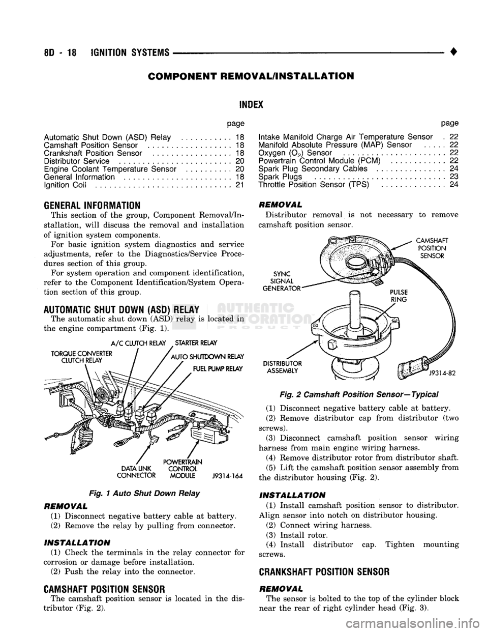
The automatic shut down
(ASD)
relay
is
located
in
the engine compartment
(Fig. 1).
TORQUE CONVERTER
CLUTCH RELAY
A/C
CLUTCH RELAY STARTER RELAY
AUTO
SHUTDOWN RELAY FUEL PUMP RELAY DATA UNK
CONNECTOR POWERTRAIN
CONTROL
MODULE
J9314-164
Fig.
1
Auto
Shut Down
Relay
REMOVAL
(1) Disconnect negative battery cable
at
battery.
(2)
Remove
the
relay
by
pulling from connector.
INSTALLATION
(1) Check
the
terminals
in the
relay connector
for
corrosion
or
damage before installation.
(2)
Push
the
relay into
the
connector.
CAMSHAFT POSITION SENSOR
The camshaft position sensor
is
located
in the
dis
tributor
(Fig. 2).
REMOVAL
Distributor removal
is not
necessary
to
remove
camshaft position sensor.
CAMSHAFT POSITION
SENSOR
SYNC
SIGNAL
GENERATOR
DISTRIBUTOR
ASSEMBLY
J9314-82
Fig.
2
Camshaft Position Sensor—Typical
(1) Disconnect negative battery cable
at
battery.
(2)
Remove distributor
cap
from distributor
(two
screws).
(3) Disconnect camshaft position sensor wiring
harness from main engine wiring harness.
(4) Remove distributor rotor from distributor shaft.
(5)
Lift
the
camshaft position sensor assembly from
the distributor housing
(Fig. 2).
INSTALLATION
(1) Install camshaft position sensor
to
distributor.
Align sensor into notch
on
distributor housing.
(2)
Connect wiring harness.
(3) Install rotor.
(4) Install distributor
cap.
Tighten mounting
screws.
CRANKSHAFT
POSITION SENSOR
REMOVAL The sensor
is
bolted
to the top of the
cylinder block
near
the
rear
of
right cylinder head
(Fig. 3).
Page 374 of 1502
•
IGNITION
SYSTEMS
80 - 23
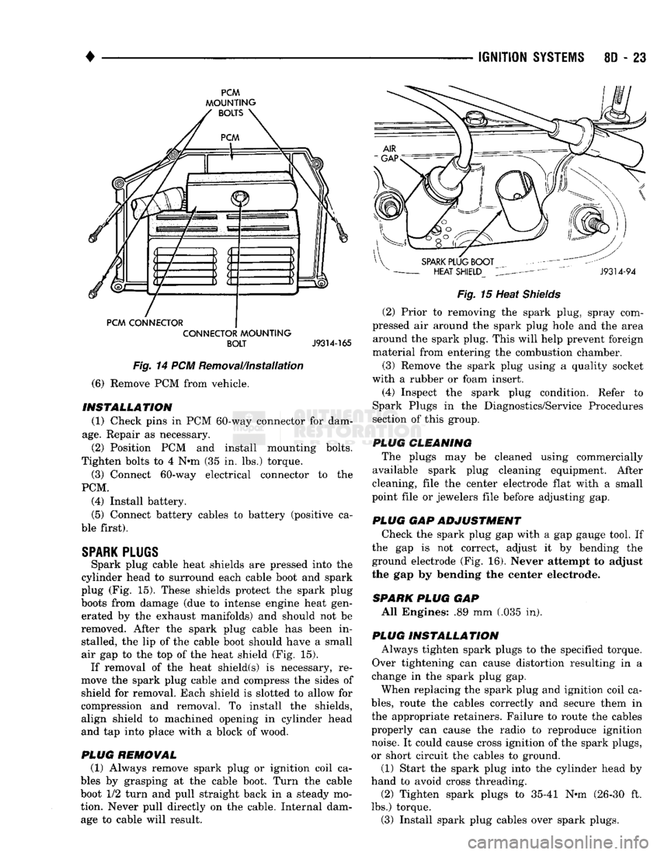
PCM
MOUNTING
PCM CONNECTOR CONNECTOR
MOUNTING
BOLT
J9314-165
Fig.
14 PCM Removal/Installation
(6) Remove PCM from vehicle.
INSTALLATION
(1) Check pins in PCM 60-way connector for dam
age.
Repair as necessary. (2) Position PCM and install mounting bolts.
Tighten bolts to 4 N»m (35 in. lbs.) torque. (3) Connect 60-way electrical connector to the
PCM. (4) Install battery.
(5) Connect battery cables to battery (positive ca
ble first).
SPARK
PLUGS
Spark plug cable heat shields are pressed into the
cylinder head to surround each cable boot and spark
plug (Fig. 15). These shields protect the spark plug
boots from damage (due to intense engine heat gen erated by the exhaust manifolds) and should not be
removed. After the spark plug cable has been in stalled, the lip of the cable boot should have a small
air gap to the top of the heat shield (Fig. 15). If removal of the heat shield(s) is necessary, re
move the spark plug cable and compress the sides of
shield for removal. Each shield is slotted to allow for
compression and removal. To install the shields, align shield to machined opening in cylinder head
and tap into place with a block of wood.
PLUG
REMOVAL
(1) Always remove spark plug or ignition coil ca
bles by grasping at the cable boot. Turn the cable
boot 1/2 turn and pull straight back in a steady mo
tion. Never pull directly on the cable. Internal dam age to cable will result.
Fig.
15 Heat
Shields
(2) Prior to removing the spark plug, spray com
pressed air around the spark plug hole and the area around the spark plug. This will help prevent foreign
material from entering the combustion chamber.
(3) Remove the spark plug using a quality socket
with a rubber or foam insert. (4) Inspect the spark plug condition. Refer to
Spark Plugs in the Diagnostics/Service Procedures
section of this group.
PLUG CLEANING The plugs may be cleaned using commercially
available spark plug cleaning equipment. After
cleaning, file the center electrode flat with a small
point file or jewelers file before adjusting gap.
PLUG GAP ADJUSTMENT Check the spark plug gap with a gap gauge tool. If
the gap is not correct, adjust it by bending the
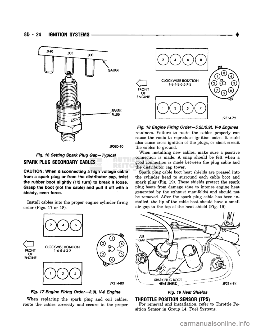
ground electrode (Fig. 16). Never attempt to adjust
the gap by bending the center electrode.
SPARK
PLUG
GAP All Engines: .89 mm (.035 in).
PLUG INSTALLATION Always tighten spark plugs to the specified torque.
Over tightening can cause distortion resulting in a
change in the spark plug gap.
When replacing the spark plug and ignition coil ca
bles,
route the cables correctly and secure them in
the appropriate retainers. Failure to route the cables
properly can cause the radio to reproduce ignition noise. It could cause cross ignition of the spark plugs,
or short circuit the cables to ground.
(1) Start the spark plug into the cylinder head by
hand to avoid cross threading. (2) Tighten spark plugs to 35-41 N-m (26-30 ft.
lbs.) torque. (3) Install spark plug cables over spark plugs.
Page 375 of 1502
8D
- 24
IGNITION
SYSTEMS
•
.040
GAUGE
SPARK
"PLUG
J908D-10
Fig.
16 Setting
Spark Plug
Gap—Typical
SPARK
PLUG
SECONDARY
CABLES
CAUTION:
When disconnecting
a
high voltage cable
from
a
spark plug
or
from
the
distributor cap, twist
the rubber boot slightly
(1/2
turn)
to
break
it
loose.
Grasp
the
boot
(not
the
cable)
and
pull
it off
with
a
steady,
even force.
Install cables into
the
proper engine cylinder firing
order (Figs.
17 or 18).
FRONT OF
ENGINE
CLOCKWISE
ROTATION
1-6-5-4-3-2
J9314-80
Fig.
17
Engine
Firing Order—3.9L V-6
Engine
When replacing
the
spark plug
and
coil cables,
route
the
cables correctly
and
secure
in the
proper a
FRONT OF
ENGINE
CLOCKWISE
ROTATION
1-8-4-3-6-5-7-2
J9314-79
Fig.
18
Engine
Firing Order—5.2U5.9L V-8
Engines
retainers. Failure
to
route
the
cables properly
can
cause
the
radio
to
reproduce ignition noise.
It
could
also cause cross ignition
of the
plugs,
or
short circuit
the cables
to
ground.
When installing
new
cables, make sure
a
positive
connection
is
made.
A
snap should
be
felt when
a
good connection
is
made between
the
plug cable
and
the distributor
cap
tower.
Spark plug cable boot heat shields
are
pressed into
the cylinder head
to
surround each cable boot
and
spark plug
(Fig. 19).
These shields protect
the
spark
plug boots from damage
(due to
intense engine heat generated
by the
exhaust manifolds)
and
should
not
be removed. After
the
spark plug cable
has
been
in
stalled,
the lip of the
cable boot should have
a
small
air
gap to the top of the
heat shield
(Fig. 19).
SPARK
PLUG BOOT
-
HEAT SHIELD
J9314-94
Fig.
19 Heat
Shields
THROTTLE
POSITION
SENSOR
(TPS) For removal
and
installation, refer
to
Throttle
Po
sition Sensor
in
Group
14,
Fuel Systems.
Page 379 of 1502

8D
- 28
IGNITION
SYSTEMS
•
GENERAL
INFORMATION
The following specifications
are
published from
the
latest information available
at the
time
of
publica
tion.
If
anything differs between
the
specifica
tions found
on the
Vehicle Emission Control Information (VECI) label
and the
following spec
ifications,
use
specifications
on
VECI label.
The
SPECIFICATIONS
VECI label
is
located
in the
engine compartment.
IGNITION
TIMING
Ignition timing
is not
adjustable
on any
engine.
Refer
to
Ignition Timing
in the
Diagnostics/Service
Procedures section
of
this group
for
more informa
tion.
IGNITION
COIL
COii
TOYODSNSO
Primary Resistance .95-
1.20
Ohms .96-
1.18
Ohms
Secondary
Resistance
at
70°
-
80
°F
11,300-
13,300
Ohms
11,300
-
15,300
Ohms
SPARK PLUGS J918D-25
Engine
Spark
Plug
Application
Gap
Tightening
Torque Size
Engine
Original
Equipment Replacement Application
Gap
Tightening
Torque Size
3.9L/5.2L/5.9L
RC12YC RC12YC
All
.035°
(0.9mm)
41
Nm
(30
ft.
lbs.)
14mm
%"
Reach
J928D-23
SPARK PLUG CABLE RESISTANCE
ENGINE FIRING ORDER-3.9L
V-6
ENGINE
MINIMUM
MAXIMUM
250 Ohms
Per
Inch 1000 Ohms
Per
Inch
3000
Ohms
Per
Foot
12,000
Ohms
Per
Foot
J908D-43
a
FRONT
OF
ENGINE CLOCKWISE
ROTATION
1
-6-5-4-3-2
,
©
V©
^ ©y
©
J9314-80
Page 380 of 1502
IGNITION
SYSTEMS
8D - 29
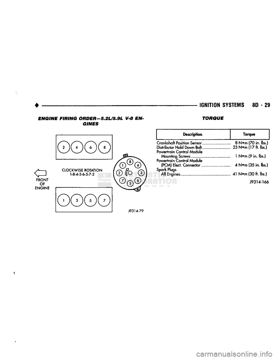
ENGINE FIRING ORDER—5.2L/5.9L V-8 EN
GINES TORQUE
FRONT
OF
ENGINE
CLOCKWISE
ROTATION
1-8-4-3-6-5-7-2
Description
Torque
Crankshaft
Position
Sensor..
Distributor Hold Down Bolt..
Powertrain
Control Module
Mounting
Screws............
Powertrain
Control Module
(PCM)
Elect. Connector...
Spark
Plugs
All Engines
8
N*m (70
in.
lbs.)
23
N«m(17ft.ibs.)
1
N«m (9 in. lbs.)
4 N*m (35
in.
lbs.)
41
N<>m
(30
ft.
lbs.)
J9314-166
J9314-79
1
Page 476 of 1502
•
WIRING DIAGRAMS
8W
- 1
CONTENTS
page page
COMPONENT IDENTIFICATION
.............
9
SPLICE LOCATIONS
29
GENERAL
INFORMATION
1
WIRING DIAGRAMS AD-BODY
37
GENERAL
INFORMATION
INDEX
page
Circuit
Identification
2
Component
Identification
3
Connectors
3
Fusible Links
3
Harness
Repair
3
Locating
A
System
or
Component
2
page
Secondary
Ignition
Wiring
1
Splice Locations
3
Symbols
and
Fuses
5
Troubleshooting
Wiring
Problems
3
Wire Code
Identification
2
Wiring
Diagram Sheets
and
Indexes
1
The wiring diagrams contain
the
latest information
available
at
time
of
publication. Throughout
out
this
group references
may
be
made
to a
particular vehicle
by letter
or
number designation.
A
chart showing
the
breakdown
of
these designations
is
included
in the
Introduction Section
of
this service manual.
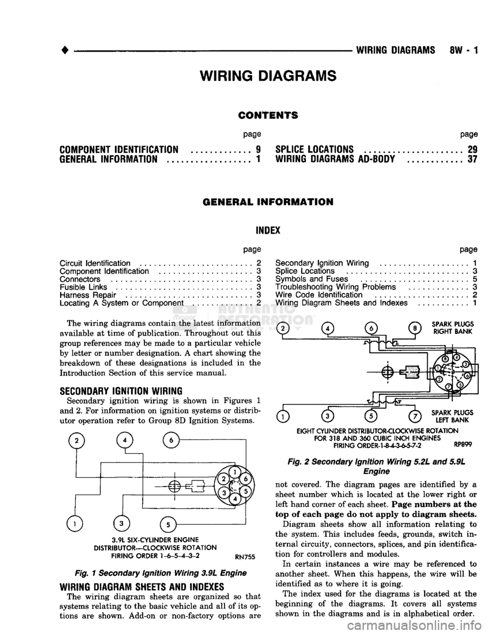
SECONDARY
IGNITION WIRING
Secondary ignition wiring
is
shown
in
Figures
1
and 2.
For
information
on
ignition systems
or
distrib
utor operation refer
to
Group
8D
Ignition Systems.
SPARK
PLUGS
RIGHT
BANK
3.9L
SIX-CYLINDER
ENGINE
DISTRIBUTOR—CLOCKWISE
ROTATION
FIRING
ORDER
1-6-5-4-3-2
RN755
Fig.
1
Secondary
Ignition Wiring 3.9L
Engine
WIRING DIAGRAM SHEETS AND INDEXES
The wiring diagram sheets
are
organized
so
that
systems relating
to the
basic vehicle
and all of
its op
tions
are
shown. Add-on
or
non-factory options
are
SPARK
PLUGS
LEFT
BANK
EIGHT
CYLINDER
DISTRIBUTOR-CLOCKWISE
ROTATION
FOR
318
AND
360
CUBIC
INCH
ENGINES
FIRING
ORDER-1-8^-3-63-7-2 RP899 Fig.
2
Secondary
Ignition Wiring 5.2L and 5.9L
Engine
not covered.
The
diagram pages
are
identified
by a
sheet number which
is
located
at the
lower right
or
left hand corner
of
each sheet. Page numbers
at the
top
of
each page
do not
apply
to
diagram sheets.
Diagram sheets show
all
information relating
to
the system. This includes feeds, grounds, switch
in
ternal circuity, connectors, splices,
and
pin
identifica
tion
for
controllers
and
modules.
In certain instances
a
wire
may be
referenced
to
another sheet. When this happens,
the
wire will
be
identified
as to
where
it is
going.
The index used
for the
diagrams
is
located
at the
beginning
of the
diagrams.
It
covers
all
systems shown
in the
diagrams
and is in
alphabetical order.
WIRING
DIAGRAMS
Page 607 of 1502

9
- 2
ENGINES
rial surrounds each mounting hole. Excess material
can easily be wiped off. Components should be
torqued in place within 15 minutes. The use of a lo cating dowel is recommended during assembly to pre
vent smearing the material off location.
ENGINE PERFORMANCE
To provide best vehicle performance and lowest ve
hicle emissions, it is most important that the tune-up
be done accurately. Use the specifications listed on
the Vehicle Emission Control Information label found on the engine compartment hood.
(1) Test cranking amperage draw (refer to Group
8B,
Battery/Starter/Generator Service for the proper
procedures).
(2) Tighten the intake manifold bolts (refer to
Group 11, Exhaust System and Intake Manifold for
the proper specifications). (3) Perform cylinder compression test:
(a) Check engine oil level and add oil, if neces
sary.
(b) Drive the vehicle until engine reaches normal
operating temperature. (c) Select a route free from traffic and other
forms of congestion, observe all traffic laws and
briskly accelerate through the gears several times. The higher engine speed may help clean out valve seat deposits which can prevent accurate compres
sion readings.
CAUTION:
DO NOT
overspeed
the
engine.
(d) Remove all spark plugs from engine. As
spark plugs are being removed, check electrodes for
abnormal firing indicators - fouled, hot, oily, etc.
Record cylinder number of spark plug for future
reference.
(e) Disconnect coil wire from distributor and se
cure to good ground to prevent a spark from start
ing a fire.
(f) Be sure throttle blades are fully open during
the compression check. (g) Insert compression gage adaptor into the
No.l spark plug hole. Crank engine until maxi
mum pressure is reached on gauge. Record this
pressure as No.l cylinder pressure.
(h) Repeat Step 3g for all remaining cylinders.
(i) Compression should not be less than 689 kPa
(100 psi) and not vary more than 172 kPa (25 psi)
from cylinder to cylinder.
(j) If cylinder(s) have abnormally low compres
sion pressures, repeat steps 3a through 3h. (k) If the same cylinder(s) repeat an abnormally
low reading, it could indicate the existence of a
problem in the cylinder.
The recommended compression pressures are
to be used only as a guide to diagnosing engine
problems. An engine should NOT be disassem bled to determine the cause of low compression
unless some malfunction is present. (4) Clean or replace spark plugs as necessary. Ad
just gap (refer to Group 8D, Ignition System for gap adjustment and torque).
(5) Test resistance of spark plug cables (refer to
Group 8D, Ignition System.
(6) Inspect the primary wire. Test coil output volt
age,
primary and secondary resistance. Replace parts as necessary (refer to Group 8D, Ignition System and
make necessary adjustment).
(7) Set ignition timing to specifications (refer to
Specification Label on engine compartment hood).
(8) Perform a combustion analysis.
(9) Test fuel pump for pressure and vacuum (refer
to Group 14, Fuel System for the proper specifica
tions).
(10) Inspect air filter element (refer to Group 0,
Lubrication and Maintenance for the proper proce
dure).
(11) Inspect crankcase ventilation system (refer to
Group 0, Lubrication and Maintenance for the proper
procedure).
(12) For emission controls refer to Group 25, Emis
sion Controls System for service procedures.
(13) Inspect and adjust accessory belt drives (refer
to Group 7, Cooling System for the proper adjust
ments).
(14) Road test vehicle as a final test.
H0NIN6
CYLINDER
BORES
Before honing, stuff plenty of clean shop towels un
der the bores and over the crankshaft to keep abra sive materials from entering the crankshaft area.
(1) Used carefully, the Cylinder Bore Sizing Hone
C-823 equipped with 220 grit stones, is the best tool
for this job. In addition to deglazing, it will reduce
taper and out-of-round as well as removing light scuffing, scoring or scratches. Usually a few strokes
will clean up a bore and maintain the required lim
its.
CAUTION:
DO NOT use rigid type
hones
to remove
cylinder
wall
glaze.
(2) Deglazing of the cylinder walls may be done if
the cylinder bore is straight and round. Use a cylin
der surfacing hone, Honing Tool C-3501, equipped
with 280 grit stones (C-3501-3810). 20-60 strokes, de
pending on the bore condition, will be sufficient to
provide a satisfactory surface. Using honing oil C-3501-3880 or a light honing oil available from ma
jor oil distributors.
CAUTION:
DO NOT use engine or
transmission
oil, mineral
spirits
or
kerosene.
Page 609 of 1502
9
- 4 ENGINES
•
RN861
Fig. 3 Clearance Measurement
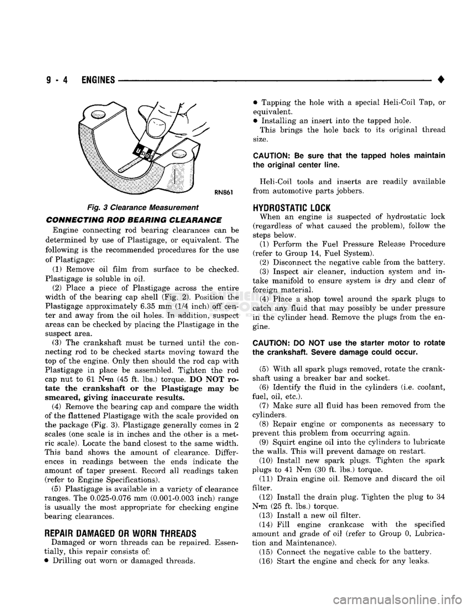
CONNECTING ROD BEARING CLEARANCE Engine connecting rod bearing clearances can be
determined by use of Plastigage, or equivalent. The
following is the recommended procedures for the use of Plastigage:
(1) Remove oil film from surface to be checked.
Plastigage is soluble in oil.
(2) Place a piece of Plastigage across the entire
width of the bearing cap shell (Fig. 2). Position the
Plastigage approximately 6.35 mm (1/4 inch) off cen
ter and away from the oil holes. In addition, suspect areas can be checked by placing the Plastigage in the
suspect area. (3) The crankshaft must be turned until the con
necting rod to be checked starts moving toward the
top of the engine. Only then should the rod cap with
Plastigage in place be assembled. Tighten the rod
cap nut to 61 Nnn (45 ft. lbs.) torque. DO NOT ro
tate the crankshaft or the Plastigage may be smeared, giving inaccurate results. (4) Remove the bearing cap and compare the width
of the flattened Plastigage with the scale provided on
the package (Fig. 3). Plastigage generally comes in 2 scales (one scale is in inches and the other is a met
ric scale). Locate the band closest to the same width.
This band shows the amount of clearance. Differ ences in readings between the ends indicate the
amount of taper present. Record all readings taken (refer to Engine Specifications). (5) Plastigage is available in a variety of clearance
ranges. The 0.025-0.076 mm (0.001-0.003 inch) range
is usually the most appropriate for checking engine
bearing clearances.
REPAIR DAMAGED OR WORN THREADS Damaged or worn threads can be repaired. Essen
tially, this repair consists of:
• Drilling out worn or damaged threads. • Tapping the hole with a special Heli-Coil Tap, or
equivalent.
• Installing an insert into the tapped hole.
This brings the hole back to its original thread
size.
CAUTION:
Be
sure
that
the tapped holes maintain
the original
center
line.
Heli-Coil tools and inserts are readily available
from automotive parts jobbers.
HYDROSTATIC
LOCK
When an engine is suspected of hydrostatic lock
(regardless of what caused the problem), follow the
steps below. (1) Perform the Fuel Pressure Release Procedure
(refer to Group 14, Fuel System). (2) Disconnect the negative cable from the battery.
(3) Inspect air cleaner, induction system and in
take manifold to ensure system is dry and clear of
foreign material. (4) Place a shop towel around the spark plugs to
catch any fluid that may possibly be under pressure
in the cylinder head. Remove the plugs from the en
gine.
CAUTION:
DO NOT use the starter motor to
rotate
the
crankshaft.
Severe
damage
could
occur.
(5) With all spark plugs removed, rotate the crank
shaft using a breaker bar and socket.
(6) Identify the fluid in the cylinders (i.e. coolant,
fuel, oil, etc.).
(7) Make sure all fluid has been removed from the
cylinders. (8) Repair engine or components as necessary to
prevent this problem from occurring again.
(9) Squirt engine oil into the cylinders to lubricate
the walls. This will prevent damage on restart.
(10) Install new spark plugs. Tighten the spark
plugs to 41 N#m (30 ft. lbs.) torque. (11) Drain engine oil. Remove and discard the oil
filter.
(12) Install the drain plug. Tighten the plug to 34
N-m (25 ft. lbs.) torque.
(13) Install a new oil filter.
(14) Fill engine crankcase with the specified
amount and grade of oil (refer to Group 0, Lubrica
tion and Maintenance). (15) Connect the negative cable to the battery.
(16) Start the engine and check for any leaks.