1993 DODGE TRUCK spark plugs
[x] Cancel search: spark plugsPage 611 of 1502

9
- 6
ENGINES
•
SERVICE DIAGNOSIS (GASOLINE ENGINES)
•
PERFORMANCE (CONT.)
1
CONDITION
POSSIBLE
CAUSES
^
CORRECTION
1
ENGINE
LOSS
OF
POWER
1.
Incorrect ignition timing.
2. Worn or burned distributor
rotor.
3. Worn distributor shaft.
4.
Dirty
or
incorrectly
gapped
spark
plugs.
5.
Dirt
or
water
in
fuel
system.
6.
Faulty
fuel
pump.
7.
Incorrect valve timing.
8.
Blown
cylinder head
gasket.
9.
Low
compression.
10.
Burned,
warped or
pitted
valves.
11.
Plugged
or
restricted
exhaust
system.
12. Faulty ignition
cables.
13. Faulty coil.
1.
Refer
to
Group
8D, Ignition
System.
2. install new distributor
rotor.
3.
Remove
and
repair
distributor
(refer
to
Group
8D, Ignition
System).
4.
Clean
plugs
and
set gap
(refer
to
Group
8D, Ignition
System).
5. Clean
system
and replace
fuel
filter.
6. Install new
fuel
pump.
7.
Correct
valve
timing.
8. Install new cylinder head
gasket.
9.
Test
compression
of
each
cylinder.
10.
Install new
valves.
11.
Install new
parts,
as
necessary.
12.
Replace
any cracked or
shorted
cables.
13.
Test
and
replace,
as
necessary
(refer
to
Group
8D, Ignition
System).
ENGINE
MISSES
ON
ACCELERATION
1.
Dirty
or
gap set
too
wide
in spark
plug.
2. Incorrect ignition timing.
3.
Dirt
in
fuel
system.
4.
Burned,
warped or
pitted
valves.
5. Faulty coil.
1.
Clean spark
plugs
and set gap
(refer
to
Group
8D, Ignition
System).
2. Refer to
Group
8D, Ignition
System.
3. Clean
fuel
system.
4.
Install new
valves.
5.
Test
and
replace,
if
necessary,
(refer
to
Group
8D, Ignition
System).
ENGINE
MISSES
AT HIGH
SPEED
1.
Dirty
or
gap set too
wide
in spark
plug.
2. Worn distributor shaft.
3. Worn or burned distributor
rotor.
4. Faulty
coil.
5. Incorrect ignition timing.
6.
Dirty
injector
in
throttle
body.
7.
Dirt
or
water
in
fuel
system.
1.
Clean
spark
plugs
and
set gap
(refer
to
Group
8D, Ignition
System).
2.
Remove
and
repair
distributor
(refer
to
Group
8D,
Ignition
System).
3. Install new distributor
rotor.
4.
Test
and replace,
as
necessary
(refer
to
Group
8D, Ignition
System).
5.
Refer
to
Group
8D, Ignition
System.
6.
Clean
injector.
7.
Clean
system
and replace
fuel
filter.
J9309-106
Page 612 of 1502
•
ENGINES
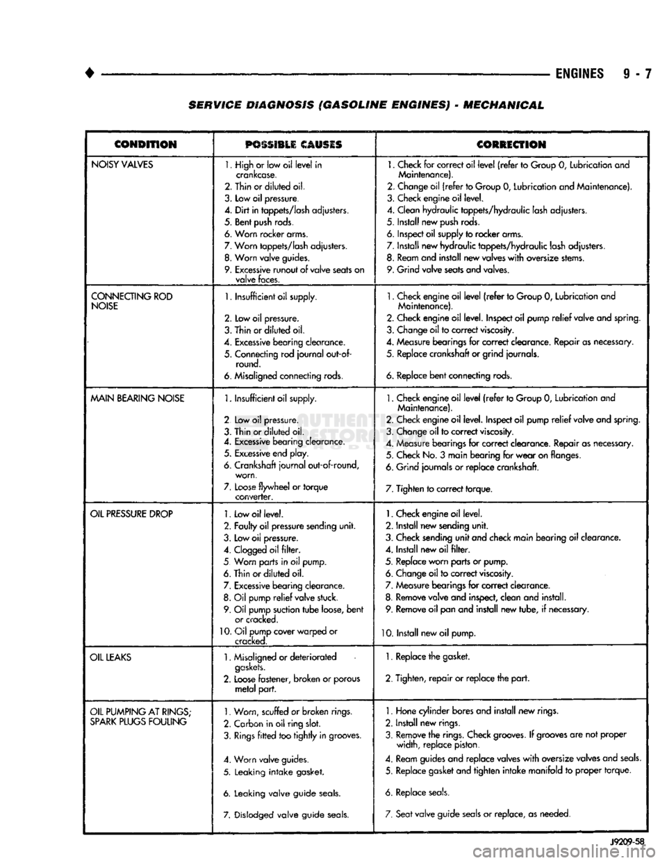
9 - 7 SERVICE DIAGNOSIS (GASOLINE ENGINES) - MECHANICAL
CONDITION
PSSSI1LI
CAUSIS
CORRECTION
NOISY
VALVES
1. High
or
low oil
level
in
crankcase.
2. Thin or
diluted
oil.
3.
Low
oil
pressure.
4.
Dirt
in
tappets/lash
adjusters.
5. Bent
push
rods.
6. Worn rocker arms.
7.
Worn
tappets/lash
adjusters.
8.
Worn
valve
guides.
9.
Excessive
runout
of
valve
seats
on
valve
faces.
1.
Check
for
correct oil
level
(refer
to
Group
0,
Lubrication and
Maintenance).
2. Change oil
(refer
to Group
0,
Lubrication and Maintenance).
3. Check engine oil level.
4. Clean hydraulic tappets/hydraulic lash adjusters.
5. Install new
push
rods.
6. Inspect oil supply to rocker arms.
7. Install new hydraulic tappets/hydraulic lash adjusters. 8. Ream and install new valves
with
oversize stems.
9. Grind valve seats and valves.
CONNECTING
ROD
NOISE
1.
Insufficient oil supply.
2.
Low oil
pressure.
3.
Thin
or
diluted
oil.
4.
Excessive
bearing
clearance.
5. Connecting rod
journal
out-of- round.
6. Misaligned connecting rods.
1.
Check engine oil
level
(refer
to Group
0,
Lubrication and
Maintenance).
2. Check engine oil level. Inspect oil pump
relief
valve and spring.
3. Change oil to correct
viscosity.
4. Measure bearings for correct clearance. Repair as necessary, 5. Replace crankshaft or grind journals.
6.
Replace
bent
connecting rods.
MAIN
BEARING
NOISE
1.
Insufficient oil supply.
2 Low
oil
pressure.
3. Thin or
diluted
oil.
4.
Excessive
bearing clearance. 5.
Excessive
end play.
6. Crankshaft
journal
out-of-round, worn,
7.
Loose
flywheel
or
torque
converter.
1.
Check engine oil
level
(refer
to Group
0,
Lubrication and
Maintenance).
2. Check engine oil level. Inspect oil pump
relief
valve and spring.
3. Change oil to correct
viscosity.
4. Measure bearings for correct clearance. Repair as necessary. 5. Check No.
3
main bearing for
wear
on flanges.
6. Grind journals
or
replace crankshaft.
7. Tighten to correct torque.
OIL
PRESSURE
DROP
1.
Low oil level.
2. Faulty oil pressure sending
unit.
3. Low
oil
pressure.
4.
Clogged
oil
filter.
5 Worn parts in
oil
pump.
6. Thin or
diluted
oil.
7.
Excessive
bearing clearance. 8.
Oil
pump
relief
valve stuck.
9. Oil pump suction
tube
loose,
bent
or cracked.
10.
Oil pump cover warped
or
cracked.
1.
Check engine oil level.
2. Install new sending
unit.
3. Check sending
unit
and check main bearing oil clearance.
4. Install new oil
filter.
5. Replace worn parts or pump. 6. Change oil to correct
viscosity.
7. Measure bearings for correct clearance.
8. Remove valve and inspect, clean and install. 9. Remove oil pan and install new tube,
if
necessary.
10. Install new oil pump.
OIL
LEAKS
1.
Misaligned or
deteriorated
gaskets.
2.
Loose
fastener, broken
or
porous
metal
part.
1. Replace the gasket.
2. Tighten,
repair
or replace the
part.
OIL
PUMPING
AT
RINGS;
SPARK
PLUGS
FOULING
1.
Worn, scuffed
or broken
rings.
2. Carbon in oil ring
slot.
3.
Rings
fitted
too
tightly
in grooves.
4. Worn valve guides.
5. Leaking
intake
gasket.
6. Leaking valve guide
seals.
7. Dislodged valve guide
seals.
1.
Hone cylinder bores and install new rings.
2. Install new rings.
3. Remove the rings. Check
grooves.
If
grooves
are not proper width, replace piston.
4. Ream guides and replace valves
with
oversize valves and
seals.
5. Replace gasket and tighten
intake
manifold
to
proper torque.
6. Replace
seals.
7. Seat
valve guide
seals
or
replace, as needed.
J9209-58
Page 627 of 1502
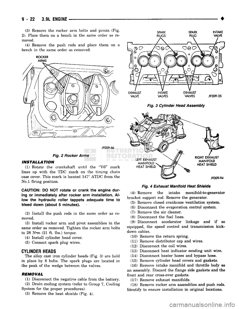
(3) Remove the rocker arm bolts and pivots (Fig.
2).
Place them on a bench in the same order as re
moved.
(4) Remove the push rods and place them on a
bench in the same order as removed.
ROCKER
ARMS
J9209-66
Fig.
2
Rocker Arms
INSTALLATION
(1) Rotate the crankshaft until the "V6" mark
lines up with the TDC mark on the timing chain
case cover. This mark is located 147° ATDC from the
No.l firing position.
CAUTION:
DO NOT
rotate
or
crank
the
engine dur
ing
or
immediately
after
rocker
arm
installation.
Al
low
the
hydraulic roller tappets adequate time
to
bleed down (about
5
minutes).
(2) Install the push rods in the same order as re
moved.
(3) Install rocker arm and pivot assemblies in the
same order as removed. Tighten the rocker arm bolts
to 28 N*m (21 ft. lbs.) torque.
(4) Install cylinder head cover.
(5) Connect spark plug wires.
CYLINDER
HEADS
The alloy cast iron cylinder heads (Fig. 3) are held
in place by 8 bolts. The spark plugs are located in
the peak of the wedge between the valves.
REMOVAL
(1) Disconnect the negative cable from the battery.
(2) Drain cooling system (refer to Group 7, Cooling
System for the proper procedures). (3) Remove the heat shields (Fig. 4).
SPARK SPARK
INTAKE
PLUGS
PLUG VALVE
EXHAUST INTAKE EXHAUST VALVE VALVES VALVES
J9309-35
Fig.
3 Cylinder Head
Assembly Fig.
4
Exhaust
Manifold Heat
Shields
(4) Remove the intake manifold-to-generator
bracket support rod. Remove the generator.
(5) Remove closed crankcase ventilation system.
(6) Disconnect the evaporation control system.
(7) Remove the air cleaner.
(8) Disconnect the fuel lines.
(9) Disconnect accelerator linkage and if so
equipped, the speed control and transmission kick-
down cables. (10) Remove the return spring.
(11) Remove distributor cap and wires.
(12) Disconnect the coil wires.
(13) Disconnect heat indicator sending unit wire.
(14) Disconnect heater hoses and bypass hose.
(15) Remove cylinder head covers and gaskets.
(16) Remove intake manifold and throttle body as
an assembly. Discard the flange side gaskets and the
front and rear cross-over gaskets.
(17) Remove exhaust manifolds.
(18) Remove rocker arm assemblies and push rods.
Identify to ensure installation in original locations.
Page 628 of 1502
•
3.9L
ENGINE
9 - 23 (19) Remove the head bolts from each cylinder
head and remove cylinder heads. Discard the cylin der head gasket.
(20) Remove spark plugs.
CLEANING
Clean all surfaces of cylinder block and cylinder
heads.
Clean cylinder block front and rear gasket surfaces
using a suitable solvent.
INSPECTION
Inspect all surfaces with a straightedge if there is
any reason to suspect leakage. If out-of-flatness ex
ceeds 0.00075 mm/mm (0.00075 inch/inch) times the
span length in any direction, either replace head or
lightly machine the head surface.
FOR EXAMPLE:—A 305 mm (12 inch) span is
0.102 mm (0.004 inch) out-of-flat. The allowable out-
of-flat is 305 x 0,00075 (12 x 0.00075) equals 0.23
mm (0.009 inch). This amount of out-of-flat is accept
able.
The cylinder head surface finish should be 1.78-
3.00 microns (70-125 microinches). Inspect push rods. Replace worn or bent rods.
INSTALLATION
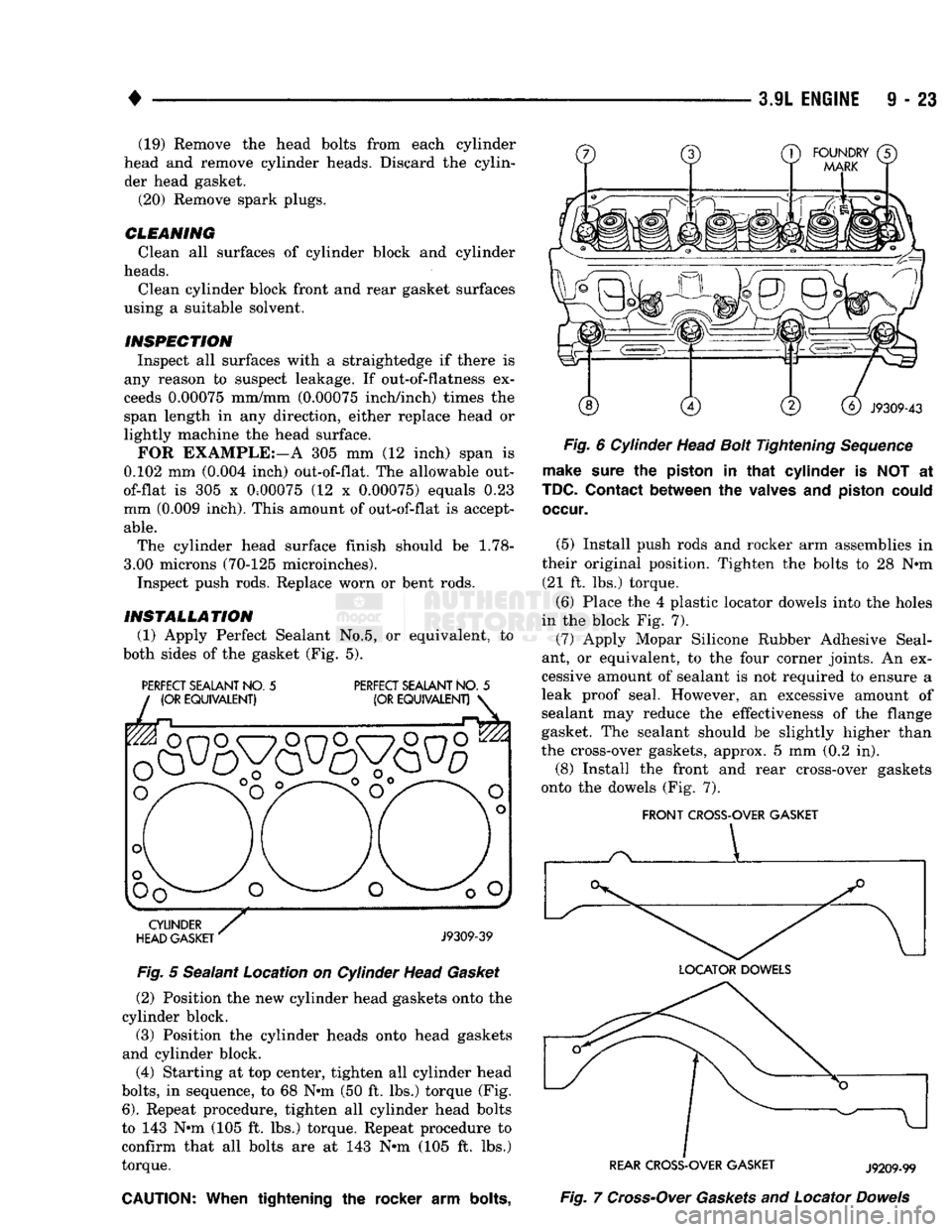
(1) Apply Perfect Sealant No.5, or equivalent, to
both sides of the gasket (Fig. 5).
PERFECT
SEALANT
NO.
5
PERFECT
SEALANT
NO.
5
Fig.
5 Sealant Location on Cylinder Head
Gasket
(2) Position the new cylinder head gaskets onto the
cylinder block.
(3) Position the cylinder heads onto head gaskets
and cylinder block.
(4) Starting at top center, tighten all cylinder head
bolts,
in sequence, to 68 N»m (50 ft. lbs.) torque (Fig.
6).
Repeat procedure, tighten all cylinder head bolts
to 143 N»m (105 ft. lbs.) torque. Repeat procedure to
confirm that all bolts are at 143 N*m (105 ft. lbs.)
torque.
CAUTION:
When
tightening the rocker arm
bolts,
Fig.
6 Cylinder Head
Bolt
Tightening
Sequence
make
sure
the
piston
in
that
cylinder is NOT at
TDC.
Contact
between the
valves
and
piston
could
occur.
(5) Install push rods and rocker arm assemblies in
their original position. Tighten the bolts to 28 Nnn (21 ft. lbs.) torque.
(6) Place the 4 plastic locator dowels into the holes
in the block Fig. 7). (7) Apply Mopar Silicone Rubber Adhesive Seal
ant, or equivalent, to the four corner joints. An ex
cessive amount of sealant is not required to ensure a
leak proof seal. However, an excessive amount of sealant may reduce the effectiveness of the flange
gasket. The sealant should be slightly higher than
the cross-over gaskets, approx. 5 mm (0.2 in).
(8) Install the front and rear cross-over gaskets
onto the dowels (Fig. 7).
FRONT
CROSS-OVER
GASKET
REAR
CROSS-OVER
GASKET
J9209-99
Fig.
7
Cross-Over
Gaskets
and Locator
Dowels
Page 629 of 1502
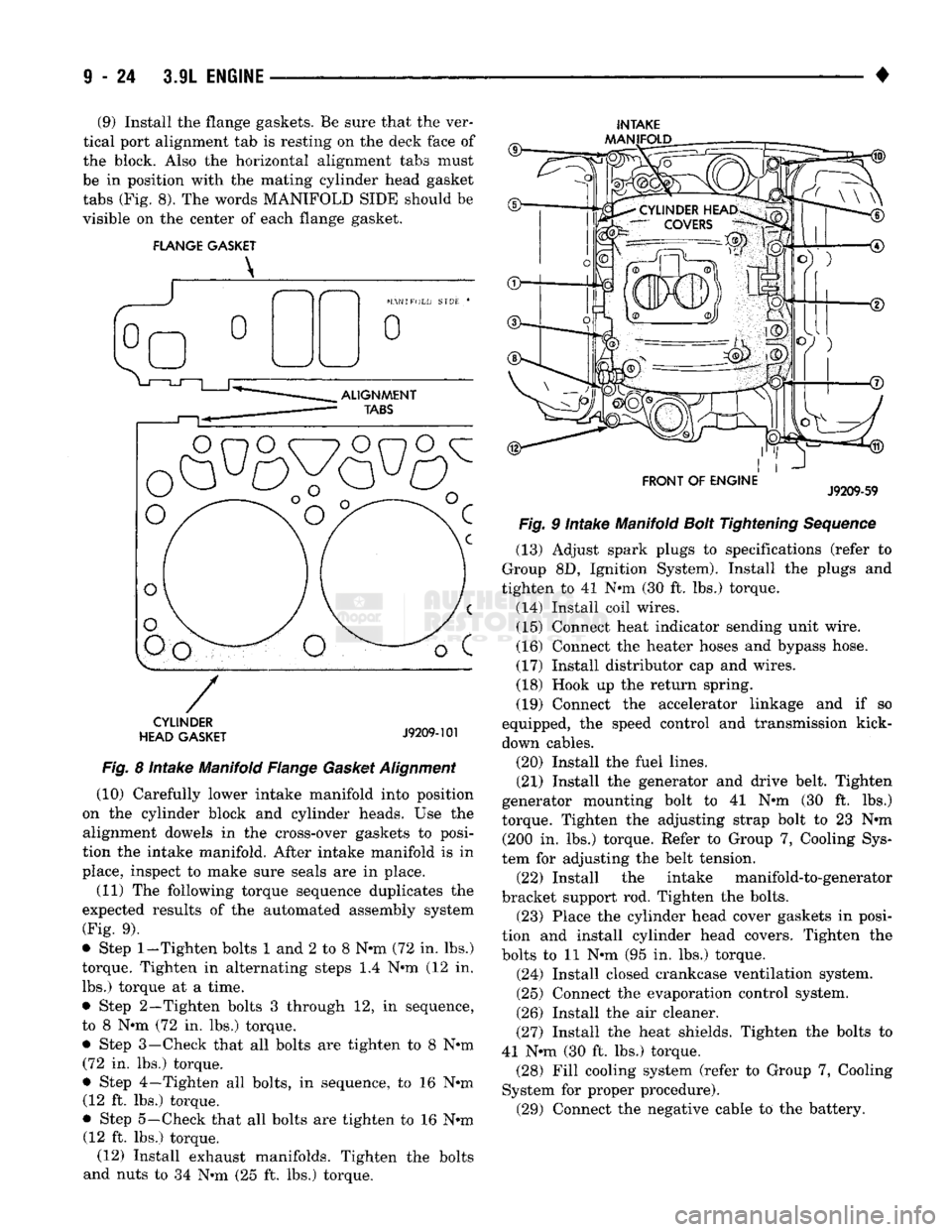
(9) Install the flange gaskets. Be sure that the ver
tical port alignment tab is resting on the deck face of
the block. Also the horizontal alignment tabs must
be in position with the mating cylinder head gasket
tabs (Fig. 8). The words MANIFOLD SIDE should be
visible on the center of each flange gasket.
FLANGE GASKET
INTAKE
AAANIFOLD
CYLINDER
HEAD GASKET
J9209-101
Fig.
8 Intake Manifold Flange
Gasket
Alignment
(10) Carefully lower intake manifold into position
on the cylinder block and cylinder heads. Use the alignment dowels in the cross-over gaskets to posi
tion the intake manifold. After intake manifold is in
place, inspect to make sure seals are in place.
(11) The following torque sequence duplicates the
expected results of the automated assembly system
(Fig. 9).
• Step
1-Tighten
bolts 1 and 2 to 8 N-m (72 in. lbs.)
torque. Tighten in alternating steps 1.4 N-m (12 in. lbs.) torque at a time.
• Step 2—Tighten bolts 3 through 12, in sequence,
to 8 N-m (72 in. lbs.) torque.
• Step 3—Check that all bolts are tighten to 8 N-m (72 in. lbs.) torque.
• Step 4—Tighten all bolts, in sequence, to 16 N-m (12 ft. lbs.) torque.
• Step 5—Check that all bolts are tighten to 16 N-m (12 ft. lbs.) torque. (12) Install exhaust manifolds. Tighten the bolts
and nuts to 34 N-m (25 ft. lbs.) torque.
FRONT OF ENGINE
J9209-59
Fig.
9 Intake Manifold
Bolt
Tightening
Sequence
(13) Adjust spark plugs to specifications (refer to
Group 8D, Ignition System). Install the plugs and
tighten to 41 N-m (30 ft. lbs.) torque.
(14) Install coil wires. (15) Connect heat indicator sending unit wire.
(16) Connect the heater hoses and bypass hose.
(17) Install distributor cap and wires.
(18) Hook up the return spring.
(19) Connect the accelerator linkage and if so
equipped, the speed control and transmission kick-
down cables.
(20) Install the fuel lines.
(21) Install the generator and drive belt. Tighten
generator mounting bolt to 41 N-m (30 ft. lbs.)
torque. Tighten the adjusting strap bolt to 23 N-m (200 in. lbs.) torque. Refer to Group 7, Cooling Sys
tem for adjusting the belt tension. (22) Install the intake manifold-to-generator
bracket support rod. Tighten the bolts. (23) Place the cylinder head cover gaskets in posi
tion and install cylinder head covers. Tighten the
bolts to 11 N-m (95 in. lbs.) torque.
(24) Install closed crankcase ventilation system.
(25) Connect the evaporation control system.
(26) Install the air cleaner.
(27) Install the heat shields. Tighten the bolts to
41 N-m (30 ft. lbs.) torque. (28) Fill cooling system (refer to Group 7, Cooling
System for proper procedure). (29) Connect the negative cable to the battery.
Page 632 of 1502
•
3.9L
ENGINE
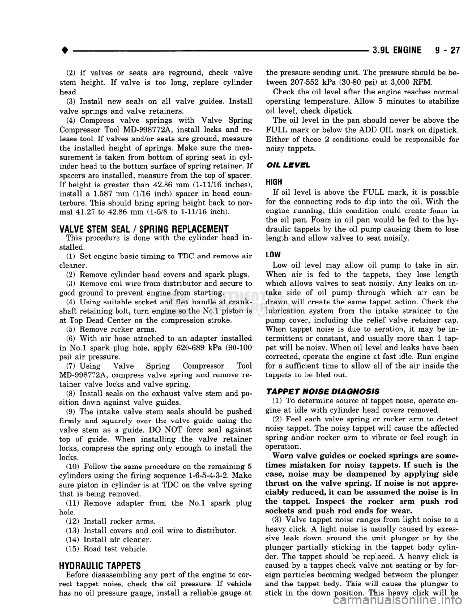
9 - 27 (2) If valves or seats are reground, check valve
stem height. If valve is too long, replace cylinder
head.
(3) Install new seals on all valve guides. Install
valve springs and valve retainers.
(4) Compress valve springs with Valve Spring
Compressor Tool MD-998772A, install locks and re
lease tool. If valves and/or seats are ground, measure
the installed height of springs. Make sure the mea surement is taken from bottom of spring seat in cyl
inder head to the bottom surface of spring retainer. If
spacers are installed, measure from the top of spacer.
If height is greater than 42.86 mm (1-11/16 inches), install a 1.587 mm (1/16 inch) spacer in head coun-
terbore. This should bring spring height back to nor
mal 41.27 to 42.86 mm (1-5/8 to
1-11/16
inch).
VALVE STEM SEAL
/
SPRING REPLACEMENT
This procedure is done with the cylinder head in
stalled. (1) Set engine basic timing to TDC and remove air
cleaner. (2) Remove cylinder head covers and spark plugs.
(3) Remove coil wire from distributor and secure to
good ground to prevent engine from starting. (4) Using suitable socket and flex handle at crank
shaft retaining bolt, turn engine so the No.l piston is
at Top Dead Center on the compression stroke. (5) Remove rocker arms.
(6) With air hose attached to an adapter installed
in No.l spark plug hole, apply 620-689 kPa (90-100
psi) air pressure. (7) Using Valve Spring Compressor Tool
MD-998772A, compress valve spring and remove re
tainer valve locks and valve spring. (8) Install seals on the exhaust valve stem and po
sition down against valve guides. (9) The intake valve stem seals should be pushed
firmly and squarely over the valve guide using the valve stem as a guide. DO NOT force seal against
top of guide. When installing the valve retainer
locks,
compress the spring only enough to install the
locks.
(10) Follow the same procedure on the remaining 5
cylinders using the firing sequence
1-6-5-4-3-2.
Make sure piston in cylinder is at TDC on the valve spring
that is being removed. (11) Remove adapter from the No.l spark plug
hole.
(12) Install rocker arms.
(13) Install covers and coil wire to distributor.
(14) Install air cleaner.
(15) Road test vehicle.
HYDRAULIC
TAPPETS
Before disassembling any part of the engine to cor
rect tappet noise, check the oil pressure. If vehicle
has no oil pressure gauge, install a reliable gauge at the pressure sending unit. The pressure should be be
tween 207-552 kPa (30-80 psi) at 3,000 RPM.
Check the oil level after the engine reaches normal
operating temperature. Allow 5 minutes to stabilize
oil level, check dipstick.
The oil level in the pan should never be above the
FULL mark or below the ADD OIL mark on dipstick.
Either of these 2 conditions could be responsible for
noisy tappets.
OIL
LEWEL
HIGH
If oil level is above the FULL mark, it is possible
for the connecting rods to dip into the oil. With the engine running, this condition could create foam in
the oil pan. Foam in oil pan would be fed to the hy draulic tappets by the oil pump causing them to lose
length and allow valves to seat noisily.
LOW
Low oil level may allow oil pump to take in air.
When air is fed to the tappets, they lose length
which allows valves to seat noisily. Any leaks on in
take side of oil pump through which air can be drawn will create the same tappet action. Check the
lubrication system from the intake strainer to the
pump cover, including the relief valve retainer cap.
When tappet noise is due to aeration, it may be in
termittent or constant, and usually more than 1 tap
pet will be noisy. When oil level and leaks have been corrected, operate the engine at fast idle. Run engine
for a sufficient time to allow all of the air inside the
tappets to be bled out.
TAPPET
NOISE DIAGNOSIS
(1) To determine source of tappet noise, operate en
gine at idle with cylinder head covers removed. (2) Feel each valve spring or rocker arm to detect
noisy tappet. The noisy tappet will cause the affected
spring and/or rocker arm to vibrate or feel rough in
operation.
Worn valve guides or cocked springs are some
times mistaken for noisy tappets. If such is the
case, noise may be dampened by applying side
thrust on the valve spring. If noise is not appre ciably reduced, it can be assumed the noise is in
the tappet. Inspect the rocker arm push rod sockets and push rod ends for wear.
(3) Valve tappet noise ranges from light noise to a
heavy click. A light noise is usually caused by exces sive leak down around the unit plunger or by the
plunger partially sticking in the tappet body cylin der. The tappet should be replaced. A heavy click is
caused by a tappet check valve not seating or by for
eign particles becoming wedged between the plunger
and the tappet body. This will cause the plunger to
stick in the down position. This heavy click will be
Page 651 of 1502
9
- 46 3.9L
ENGINE
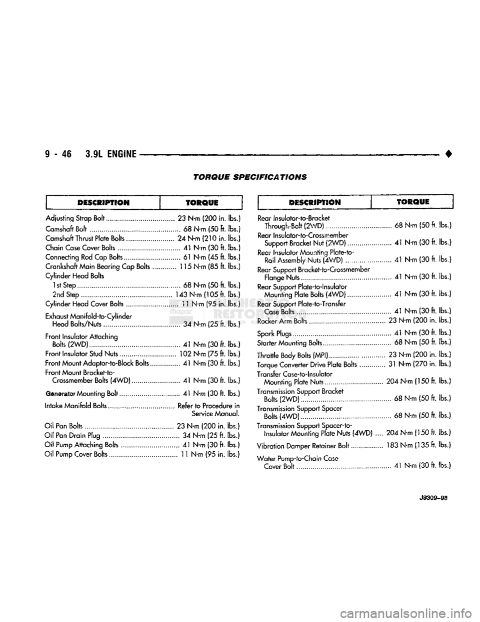
TORQUE
SPECIFICATIONS
DESCRIPTION
TORQUE
DESCRIPTION
TORQUE
Adjusting Strap Bolt.....
23
N-m
(200
in. lbs.) Camshaft Bolt
68
N-m (50 ft. lbs.j
Camshaft Thrust
Plate
Bolts
24
N-m
(210
in. lbs.)
Chain Case Cover
Bolts
41
N-m
(30 ft.
lbs.)
Connecting Rod Cap Bolts
61
N*m
(45 ft.
lbs.) Crankshaft Main Bearing Cap
Bolts
115 N-m
(85 ft.
lbs.}
Cylinder Head Bolts
1st Step
. 68
N-m
(50 ft.
lbs.)
2nd Step
.............................................
143 N-m (105 ft. lbs.)
Cylinder Head Cover
Bolts
11 N-m
(95
in. lbs.)
Exhaust ManifoId-to-Cylinder Head Bolts/Nuts
34
N-m
(25 ft.
lbs.)
Front
Insulator Attaching
Bolts
(2WD)...
41
N-m
(30 ft.
lbs.)
Front
Insulator Stud Nuts
102
N-m
(75 ft.
lbs.)
Front
Mount Adaptor-to-Block
Bolts..
41
N-m
(30 ft.
lbs.)
Front
Mount Bracket-to- Crossmember
Bolts
(4WD).
41
N-m
(30 ft.
lbs.)
Generator Mounting Bolt
41
N-m
(30 ft.
lbs.)
Intake
Manifold Bolts Refer to Procedure
in
Service Manual.
Oil Pan Bolts
23
N-m
(200
in.
lbs.)
Oil Pan Drain Plug
34
N-m
(25 ft.
lbs.)
Oil Pump Attaching Bolts
41
N-m
(30 ft. lbs.)
Oil Pump Cover
Bolts
11
N-m
(95
in. lbs.) Rear Insulalor-to-Bracket
Through-Bolt (2WD)
68
N-rn
(50 ft. lbs.)
Rear Insuiator-to-Crossmember Support Bracket Nut (2WDJ
.. 41
N-m
(30 ft.
lbs.
Rear Insulator Mounting Plate-to- Rail Assembly
Nuts (4WD)
......................
41
N-m
(30 ft. lbs.
Rear Support Bracket-to-Crossmember Flange Nuts....
41
N-m
(30 ft.
lbs.
Rear Support Plate-to-lnsulator Mounting
Plate
Bolts
(4WD) 41
N-m
(30
ft. lbs.
Rear Support Plate-to-Transfer
Case
Bolts
41
N-m
(30 ft.
lbs.
Rocker Arm Bolts
23
N-m
(200
in. lbs.
Spark
Plugs.......
41
N-m
(30 ft. lbs.
Sfarfer Counting
Bolts.
68
N-m
(50 ft.
lbs.
Throttle
Body
Bolts
(MPI)
23
N-m
(200
in. lbs.
Torque Converter Drive
Plate
Bolts
31
N-m
(270
in. lbs.
Transfer Case-to-Insulator Mounting
Plate
Nuts..............
204
N-m
(150
ft. lbs.
Transmission
Support Bracket
Bolts
(2WD)
68
N-m
(50 ft.
lbs.
Transmission
Support Spacer
Bolts
(4WD).
68
N-m
(50 ft.
lbs.
Transmission
Support Spacer-to-
Insulator Mounting
Plate
Nuts (4WD)
.... 204
N-m
(150 ft.
lbs.
Vibration Damper
Retainer
Bolt................ 183 N-m (135
ft.
lbs.
Water
Pump-to-Chain Case Cover Bolt...
41
N-m
(30
ft. lbs.)
J9309-S8
Page 657 of 1502
9
- 52 5.2L
ENGINE
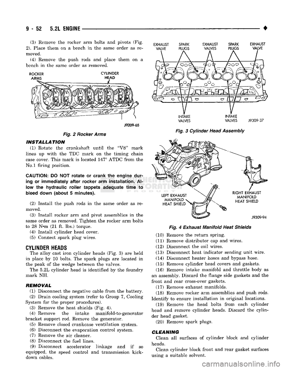
• (3) Remove the rocker arm bolts and pivots (Fig,
2).
Place them on a bench in the same order as re
moved.
(4) Remove the push rods and place them on a
bench in the same order as removed.
ROCKER
CYLINDER
J9209-65
Fig.
2
Rocker
Arms INSTALLATION
(1) Rotate the crankshaft until the "V8" mark
lines up with the TDC mark on the timing chain
case cover. This mark is located 147° ATDC from the
No.l firing position.
CAUTION:
DO NOT
rotate
or crank the engine dur
ing
or immediately
after
rocker arm installation. Al
low
the hydraulic roller tappets adequate
time
to
bleed
down
(about 5 minutes).
(2) Install the push rods in the same order as re
moved.
(3) Install rocker arm and pivot assemblies in the
same order as removed. Tighten the rocker arm bolts
to 28 N-m (21 ft. lbs.) torque. (4) Install cylinder head cover.
(5) Connect spark plug wires.
CYLINDER HEADS
The alloy cast iron cylinder heads (Fig. 3) are held
in place by 10 bolts. The spark plugs are located in
the peak of the wedge between the valves. The 5.2L cylinder head is identified by the foundry
mark NH.
REMOVAL (1) Disconnect the negative cable from the battery.
(2) Drain cooling system (refer to Group 7, Cooling
System for the proper procedures).
(3) Remove the heat shields (Fig. 4).
(4) Remove the intake manifold-to-generator
bracket support rod. Remove the generator. (5) Remove closed crankcase ventilation system. (6) Disconnect the evaporation control system. (7) Remove the air cleaner.
(8) Disconnect the fuel lines. (9) Disconnect accelerator linkage and if so
equipped, the speed control and transmission kick- down cables.
EXHAUST SPARK EXHAUST SPARK EXHAUST
VALVE PLUGS VALVES PLUGS VALVE
INTAKE INTAKE
VALVES VALVES
J9309-37
Fig.
3 Cylinder Head
Assembly
Fig.
4
Exhaust
Manifold Heat
Shields
(10) Remove the return spring.
(11) Remove distributor cap and wires.
(12) Disconnect the coil wires.
(13) Disconnect heat indicator sending unit wire.
(14) Disconnect heater hoses and bypass hose. (15) Remove cylinder head covers and gaskets. (16) Remove intake manifold and throttle body as
an assembly. Discard the flange side gaskets and the
front and rear cross-over gaskets.
(17) Remove exhaust manifolds.
(18) Remove rocker arm assemblies and push rods.
Identify to ensure installation in original locations.
(19) Remove the head bolts from each cylinder
head and remove cylinder heads. Discard the cylin der head gasket.
(20) Remove spark plugs.
CLEANING
Clean all surfaces of cylinder block and cylinder
heads.
Clean cylinder block front and rear gasket surfaces
using a suitable solvent.