1993 DODGE TRUCK wheel
[x] Cancel search: wheelPage 1428 of 1502
•
BODY
COMPONENTS 23 - 45
LOWER
SIDE TRIM PANEL
QUARTER
WINDOW
TRIM
PANEL
ROOF
INNER PANEL
\C SCREW
QUARTER PANEL SCREW
QUARTER WINDOW QUARTER WINDOW TRIM
PANEL
TRIM
PANEL
LOWER SECTION UPPER SECTION
SCREW
ASH
RECEIVER BEZEL
ASH RECEIVER LOWER SIDE TRIM PANEL CLIP
RETAINER LOWER
SIDE TRIM PANEL ROOF
INNER PANEL
RETAINER RAIL LOWER SIDE
TRIM PANEL
AT FLOOR PANEL SCREW REAR
HEADER TRIM
PANEL
ABOVE HATCHGATE
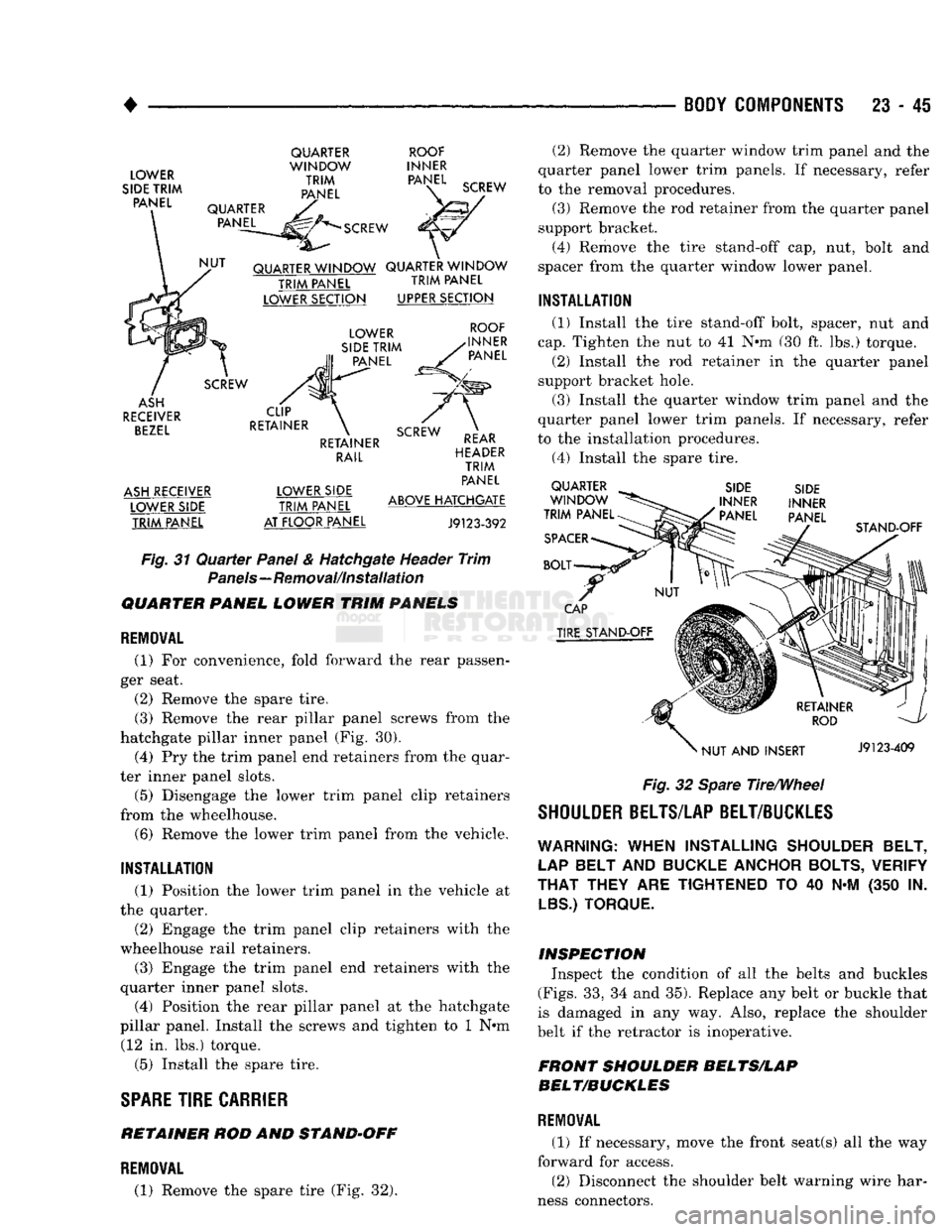
J9123-392 Fig.
31
Quarter
Panel & Hatchgate Header
Trim
Panels—Removal/Installation
QUARTER PANEL LOWER TRIM PANELS
REMOVAL
(1)
For
convenience, fold forward
the
rear passen
ger seat.
(2) Remove
the
spare tire. (3) Remove
the
rear pillar panel screws from
the
hatchgate pillar inner panel
(Fig. 30).
(4)
Pry the
trim panel end retainers from
the
quar
ter inner panel slots.
(5) Disengage
the
lower trim panel clip retainers
from
the
wheelhouse. (6) Remove
the
lower trim panel from
the
vehicle.
INSTALLATION
(1) Position
the
lower trim panel
in the
vehicle
at
the quarter.
(2) Engage
the
trim panel clip retainers with
the
wheelhouse rail retainers.
(3) Engage
the
trim panel
end
retainers with
the
quarter inner panel slots.
(4) Position
the
rear pillar panel
at the
hatchgate
pillar panel. Install
the
screws
and
tighten
to 1 N»m
(12
in. lbs.)
torque.
(5) Install
the
spare tire.
SPARE
TIRE
CARRIER
RETAINER
ROD AND
STAND-OFF
(2)
Remove
the
quarter window trim panel
and the
quarter panel lower trim panels.
If
necessary, refer
to
the
removal procedures. (3) Remove
the
rod retainer from
the
quarter panel
support bracket. (4) Remove
the
tire stand-off
cap, nut,
bolt
and
spacer from
the
quarter window lower panel.
INSTALLATION
(1) Install
the
tire stand-off bolt, spacer,
nut and
cap.
Tighten
the nut to 41 N»m (30 ft. lbs.)
torque.
(2) Install
the rod
retainer
in the
quarter panel
support bracket hole.
(3) Install
the
quarter window trim panel
and the
quarter panel lower trim panels.
If
necessary, refer
to
the
installation procedures.
(4)
Install
the
spare tire. QUARTER
WINDOW
TRIM PANEL
SPACER
BOLT SIDE
INNER
' PANEL SIDE
INNER
PANEL STAND-OFF
CAP
TIRE STAND-OFF
NUT
AND
INSERT J9123-409
Fig.
32 Spare Tire/Wheel
SHOULDER BELTS/LAP BELT/BUCKLES
WARNING:
WHEN
INSTALLING
SHOULDER BELT,
LAP
BELT
AND
BUCKLE ANCHOR BOLTS, VERIFY
THAT
THEY
ARE
TIGHTENED
TO 40 N-M (350 IN.
LBS.) TORQUE.
INSPECTION Inspect
the
condition
of all the
belts
and
buckles
(Figs.
33, 34 and
35). Replace
any
belt
or
buckle that
is damaged
in any way.
Also, replace
the
shoulder
belt
if
the retractor
is
inoperative.
FRONT SHOULDER BELTS/LAP
BELT/BUCKLES
REMOVAL
(1)
If
necessary, move
the
front seat(s)
all the way
forward
for
access. (2) Disconnect
the
shoulder belt warning wire har
ness connectors.
REMOVAL
(1) Remove
the
spare tire
(Fig. 32).
Page 1430 of 1502
•
BODY COMPONENTS 23 • 47
SPACER
SHOULDER
BELT COVER
TRIM
"PANEL
INNER
PANEL
SPACER
PILLER
SHOULDER BELT ANCHOR
BOLT
SHOULDER BELT
RETRACTOR
ANCHOR
BOLT
SHOULDER BELT
RETRACTOR
COVER
ANCHOR
BOLT
ANTI-
RATTLE
WASHER
SCREW
ANCHOR]
BOLT
RAMCHARGER
ANTI-
RATTLE
WASHER
MODELS
30 & 60
J9123-329
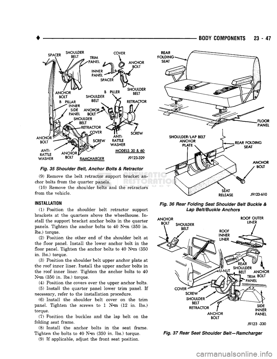
Fig.
35
Shoulder
Belt,
Anchor
Bolts
& Retractor (9) Remove the belt retractor support bracket an
chor bolts from the quarter panels.
(10) Remove the shoulder belts and the retractors
from the vehicle.
INSTALLATION
(1) Position the shoulder belt retractor support
brackets at the quarters above the wheelhouse. In stall the support bracket anchor bolts in the quarter
panels. Tighten the anchor bolts to 40 Nnn (350 in. lbs.) torque.
(2) Position the other end of the shoulder belt at
the
floor
panel. Install the lower anchor bolt in the
floor panel. Tighten the anchor bolts to 40 Nnn (350
in.
lbs.) torque.
(3) Position the shoulder belt upper anchor plate at
the roof inner liner. Install the upper anchor bolts in
the roof inner liner. Tighten the anchor bolts to 40 Nnn (350 in. lbs.) torque.
(4) Position the covers over the upper anchor bolts.
(5) Install the quarter panel lower trim panel. If
necessary, refer to the installation procedure. (6) Install the shoulder belt cover on the trim
panel. Tighten the screws to 1 Nnn (12 in. lbs.)
torque.
(7) Position the buckles and the lap belt on the
folding seat frame.
(8) Install the anchor bolts in the seat frame.
Tighten the bolts to 40 N-m (350 in. lbs.) torque.
(9) If applicable, adjust the front seat position.
REAR
FOLDING
SEAT
FLOOR
PANEL
ANCHOR
BOLT
SEAT
RELEASE
J9123-610
Fig.
36 Rear
Folding
Seat
Shoulder
Belt
Buckle
&
Lap
Belt/Buckle
Anchors
ANCHOR
BOLT
SHOULDER BELT ROOF
OUTER
LINER
COVER
•
SCREW"
SHOULDER^ BELT
RETRACTOR
ANCHOR
BOLT
SIDE
INNER PANEL
J9123 -330
Fig.
37 Rear
Seat
Shoulder
Belt—Ramcharger
Page 1435 of 1502
23
- 52
BODY COMPONENTS
SIDE
TRIM
CARPET CAB
REAR
TRIM
CARPET J9123-378
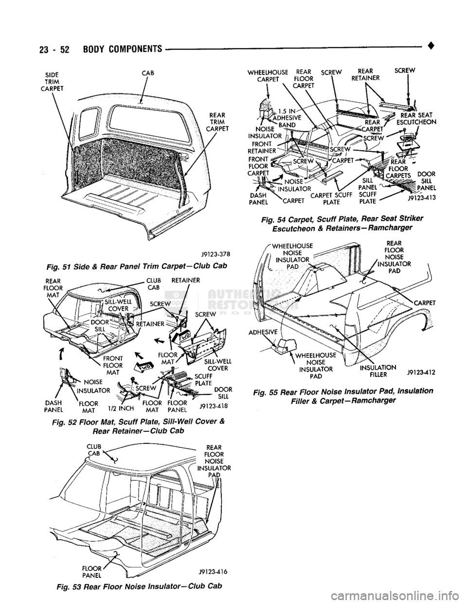
Fig. 51 Side & Rear Panel
Trim
Carpet-Club Cab
REAR
FLOOR
MAT RETAINER
DASH
PANEL
FRONT
FLOOR MAT
NOISE
INSULATOR
FLOOR MAT
1/2
INCH
FLOOR FLOOR
MAT PANEL SILL-WELL
COVER
SCUFF PLATE DOOR SILL
J9123-418
Fig. 52 Floor Mat, Scuff
Plate,
Si
11-Wei
I
Cover & Rear Retainer—Club Cab
WHEELHOUSE
REAR
SCREW
CARPET FLOOR CARPET
REAR
RETAINER SCREW
REAR
SEAT
ESCUTCHEON
,1.5 IN
ADHESIVE
NOISE
^ND
INSULATOR
nj
FRONT
~*
RETAINERS
FRONT
;
FLOOR
!
CARPET .
NOISE:
INSULATOR
DASH
\
CARPET
SCUFF
PANEL XARPET PLATE PANEL
SCUFF PLATE
REAR
*
FLOOR
CARPETS
DOOR
SILL
PANEL
J9123-413
Fig. 54
Carpet,
Scuff
Plate,
Rear Seat Striker
Escutcheon
& Retainers-Ramcharger
REAR
FLOOR NOISE
INSULATOR PAD
CARPET
ADHESIVE
;
WHEELHOUSE
NOISE
INSULATOR PAD INSULATION
FILLER
J9123-412
Fig. 55 Rear Floor Noise Insulator Pad, Insulation
Filler
& Carpet—Ramcharger
CLUB
CAB
REAR
FLOOR NOISE
INSULATOR PAD
K52' \^ J9123-416
Fig. 53 Rear Floor Noise Insulator-Club Cab
Page 1441 of 1502
24
- 4
HEATING
AND
AIR
CONDITIONING
•
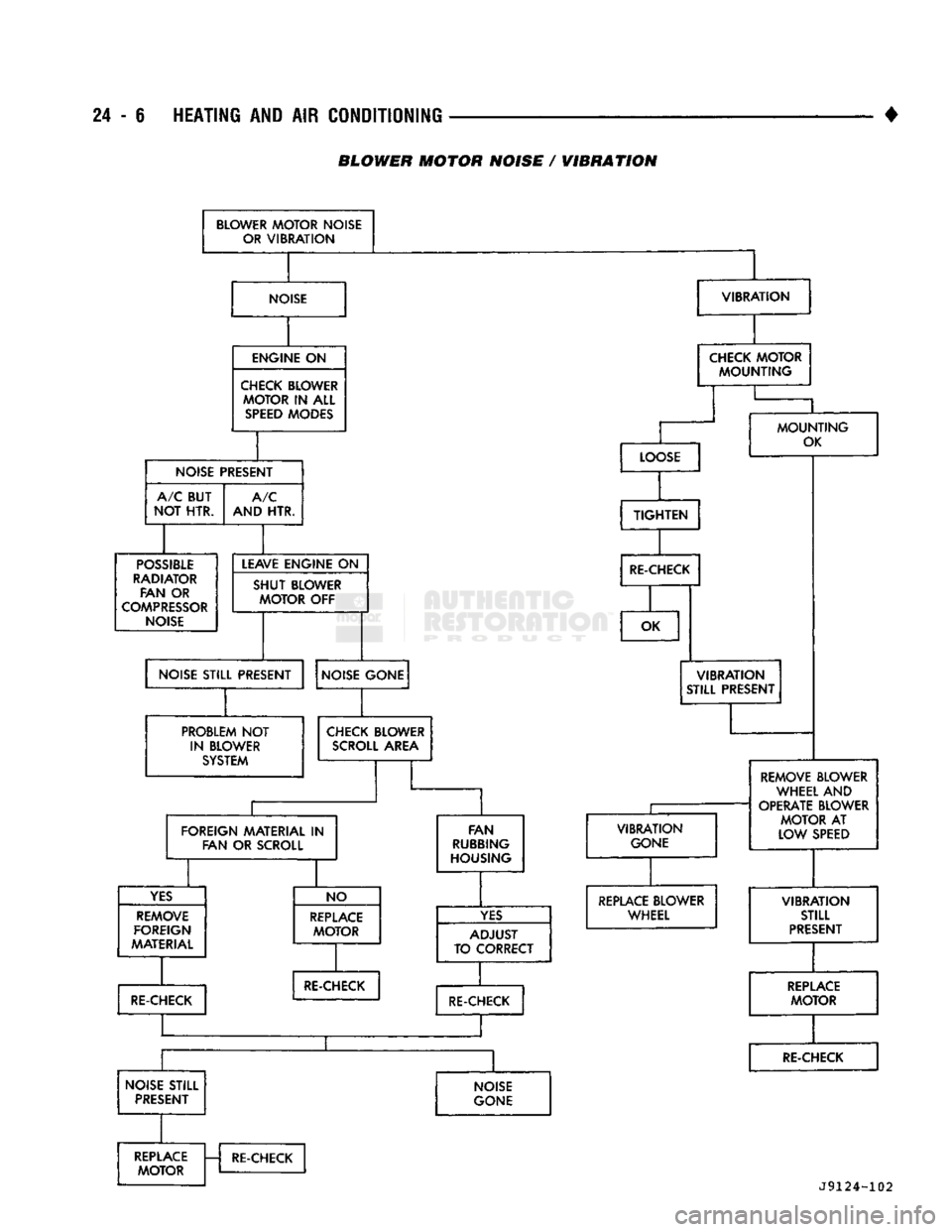
(1) Possible location or cause of blower motor vi
bration are as follows:
(a) Blower motor assembly loose in heater A/C
housing.
(b) Blower wheel loose on motor shaft.
(c) Blower wheel out of balance or bent.
(d) Blower motor defective.
(2) Possible location or cause of blower motor noise
are as follows: (To verify blower noise disconnect blower motor wire lead connector and operate heater
or A/C system. If noise goes away, proceed with pro
cedure.)
(a) Refer to vibration section of this procedure.
(b) Foreign material in Heater-A/C housing
around blower wheel.
(c) Blower wheel rubbing Heater-A/C housing.
(d) Blower motor defective.
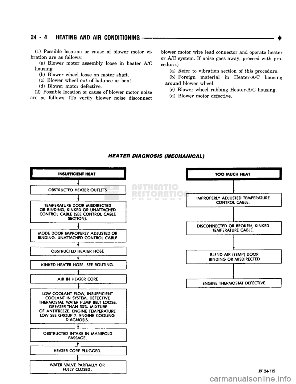
HEATER
DIAGNOSIS
(MECHANICAL)
INSUFFICIENT
HEAT
OBSTRUCTED HEATER OUTLETS
TEMPERATURE DOOR MISDIRECTED
OR BINDING, KINKED
OR
UNATTACHED
CONTROL CABLE (SEE CONTROL CABLE SECTION).
MODE DOOR IMPROPERLY ADJUSTED OR
BINDING. UNATTACHED CONTROL
CABLE.
±
OBSTRUCTED HEATER HOSE
•
KINKED HEATER HOSE, SEE ROUTING.
±
AIR
IN
HEATER CORE
LOW COOLANT FLOW, INSUFFICIENT COOLANT
IN
SYSTEM. DEFECTIVE
THERMOSTAT. WATER PUMP BELT LOOSE. GREATER
THAN
50%
MIXTURE
OF ANTIFREEZE. ENGINE TEMPERATURE LOW SEE GROUP
7.
ENGINE COOLING
DIAGNOSIS.
•
OBSTRUCTED INTAKE
IN
MANIFOLD
PASSAGE.
1_
HEATER CORE PLUGGED.
WATER VALVE PARTIALLY
OR
FULLY
CLOSED.
TOO
MUCH
HEAT
IMPROPERLY ADJUSTED TEMPERATURE CONTROL
CABLE.
DISCONNECTED
OR
BROKEN,
KINKED TEMPERATURE
CABLE.
BLEND-AIR
(TEMP)
DOOR
BINDING OR MISDIRECTED
ENGINE THERMOSTAT DEFECTIVE.
J9124-115
Page 1443 of 1502
24
- 6
HEATING AND
AIR
CONDITIONING
BLOWER MOTOR NOISE / WIBRATION
BLOWER
MOTOR
NOISE
OR
VIBRATION
NOISE
VIBRATION
ENGINE
ON
CHECK BLOWER
MOTOR
IN
ALL
SPEED
MODES CHECK
MOTOR
MOUNTING
NOISE PRESEh
n
A/C BUT
NOT HTR. A/C
AND HTR.
POSSIBLE
RADIATOR FAN
OR
COMPRESSOR
NOISE LEAVE ENGINE
ON
SHUT
BLOWER
MOTOR
OFF
NOISE STILL PRESENT LO(
DSE
TIGHTEN
RE-CHECK
MOUNTING
OK
OK
NOISE GONE
PROBLEM
NOT
IN BLOWER SYSTEM
VIBRATION
STILL PRESENT
CHECK BLOWER
SCROLL
AREA
FOREIGN MATERIAL
IN
FAN
OR
SCROLL
YES
REMOVE
FOREIGN
MATERIAL FAN
RUBBING
HOUSING NO
REPLACE
MOTOR
RE-CHECK
VIBRATION
GONE
YES
A
TO
C
DJUST
ZORRECT RE-CHECK
REMOVE BLOWER
WHEEL AND
OPERATE BLOWER
MOTOR
AT
LOW SPEED REPLACE BLOWER
WHEEL
RE-CHECK
NOISE STILL PRESENT NOISE
GONE
VIBRATION
STILL
PRESENT
REPLACE
MOTOR
RE-CHECK REPLACE
MOTOR
RE-CHECK
J9124-102
Page 1459 of 1502
24 - 22
HEATING
AND AIR
CONDITIONING
•
(4)
Remove the tape or plastic plugs from all the
suction and discharge openings and install the ser
vice valves on the compressor.
(5)
Connect the clutch lead wire.
(6) Connect the negative cable to the battery.
(7)
Evacuate, charge and test the system for leaks.
MAGNETIC
CLUTCH
The magnetic clutch consists of a stationary electro
magnetic coil and a rotating pulley and plate assembly. The electromagnetic coil is retained on the com
pressor with a snap ring and is dimpled to maintain its position. The pulley and plate assembly are mounted on the
compressor shaft. When the compressor is not in operation, the pul
ley free wheels on the clutch hub bearing. When the
coil is energized the plate is magnetically engaged
with the pulley and turns the compressor shaft.
J8924-18
Fig.
3
Clutch
Front
Plate
REMOVAL
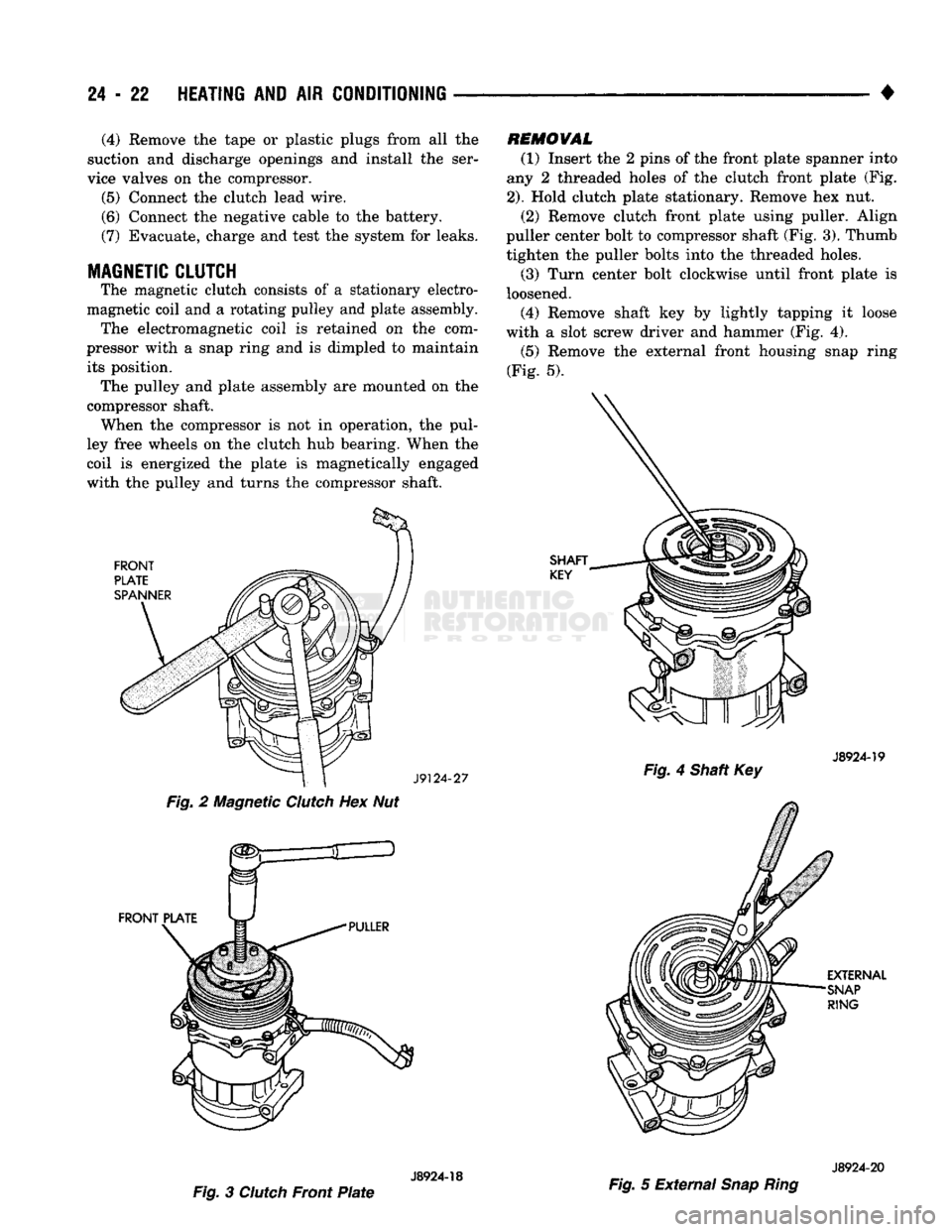
(1) Insert the 2 pins of the front plate spanner into
any 2 threaded holes of the clutch front plate (Fig.
2).
Hold clutch plate stationary. Remove hex nut. (2) Remove clutch front plate using puller. Align
puller center bolt to compressor shaft (Fig. 3). Thumb tighten the puller bolts into the threaded holes. (3) Turn center bolt clockwise until front plate is
loosened. (4) Remove shaft key by lightly tapping it loose
with a slot screw driver and hammer (Fig. 4).
(5)
Remove the external front housing snap ring
(Fig. 5).
J8924-19
Fig.
4 Shaft Key
J8924-20
Fig.
5 External
Snap Ring
Page 1474 of 1502
•
Fig.
12
Blower
Wheel
(7) Install the 3 arms. Install nut that attaches 3
door arms to doors on the top cover of the unit (Fig.
11).
INSTALLATION
(1) Install the evaporator heater assembly. Plastic
instrument panel may have to be flexed outward.
(2) Install and tighten the screw that retains the
evaporator heater assembly to cowl side sheet metal.
(3) Install the retaining nuts on engine side.
(4) Connect vacuum lines on engine side.
(5) Install blower motor connector on engine side.
(6) Remove wiring connector from resistor block.
(7) Connect vacuum lines from extension on con
trol unit and attach vacuum lines to defroster duct (Fig. 10).
(8) Connect temperature control cable to unit
through glove box. (9) Install floor air distribution duct.
(10) Install center distribution duct.
(11) Attach radio ground strap. (12) Remove right half of lower reinforcement by
removing screws attaching it to the instrument panel and the screw attaching it to the cowl side trim
panel. (13) Install ash receiver.
(14) Install structural brace through glove box
opening. Install screws and loosen nuts. (15) Install glove box by installing mounting
screws. (16) Install right cowl side trim panel, if so
equipped. (17) Position transfer case and/or gear shift levers.
(18) Remove plugs from heater hoses and unit. In
stall condensate tube (Fig. 9). (19) Connect refrigerant and heater lines to unit
on engine side.
} (20) Connect the negative cable to the battery. (21) Fill the cooling system (refer to Group 7, Cool
ing System). (22) Evacuate and charge the system.
(23) Check operation of all controls and perfor
mance of the A/C system.
HEATING
AND AIR
CONDITIONING
24 - 37
'H"
VALVE
Fig.
13
Expansion
(H)
Valve
Assembly
ELECTRONIC
TEMPERATURE
CYCLING
SWITCH
REMOVAL
(1) Remove the electrical wires to the switch.
(2) Rotate switch counterclockwise to remove from
pressure switch port. (3) Remove and discard old O-ring.
INSTALLATION
(1) Install new O-ring. Refrigerant oil must be ap
plied to the new O-ring.
(2) Rotate switch clockwise to install on suction
line pressure switch port. Tighten switch to 5.65 N#m (50 in. lbs.) torque.
CAUTION:
Power
tools
should
not be
used
for in
stallation
of the switch. The
possibility
of stripping
the
switch
threads
occurs
above
5.88 N*m (52 in.
lbs.)
torque.
(3) Connect wires. (4) Verify operation.
EXPANSION
(H)
VALVE
REMOVAL
The system must be completely discharged before
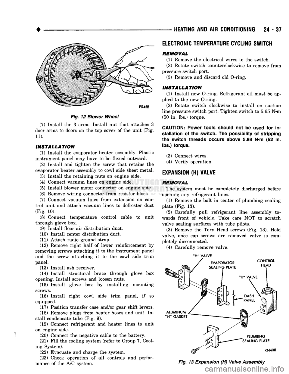
opening any refrigerant lines. (1) Remove the bolt in center of plumbing sealing
plate (Fig. 13).
(2) Carefully pull refrigerant line assembly to
wards front of vehicle. Take care NOT to scratch valve sealing surfaces with tube pilots.
(3) Remove the Torx Head screws (Fig. 13). Hold
valve, once cap screws are removed valve is com
pletely disconnected.
(4) Carefully remove valve.
Page 1483 of 1502
25
- 6
EMISSION CONTROL
SYSTEMS
•
EWAPORATIWE EMISSION CONTROLS
INDEX
page
Crankcase
Breather/Filter—Gas Powered
Engines
. . . 9
EVAP
(Evaporation)
Control
System
. 6
EVAP
Canister
. . 6
page
Evap
Canister
Purge
Solenoid
6
Fuel Tank
Filler
Tube
Cap . 7
Positive
Crankcase
Ventilation
(PCV)
System
.... 7
Pressure
Relief/Rollover Valve
6
EVAP (EVAPORATION) CONTROL SYSTEM GENERAL
INFORMATION
The function
of the
EVAP control system
is to
pre
vent
the
emissions
of
gasoline vapors from
the
fuel
tank into
the
atmosphere. When fuel evaporates
in
the fuel tank,
the
vapors pass through vent hoses
or
tubes
to a
carbon filled EVAP canister. They
are
temporarily held
in the
canister until they
can be
drawn into
the
intake manifold when
the
engine
is
running.
The vapors
are
drawn into
the
engine
at
idle
as
well
as off
idle. This system
is
called
a
Bi-level Purge
System where there
is a
dual source
of
vacuum
to re
move fuel vapor from
the
EVAP canister. The EVAP canister
is a
feature
on all
models
for
the storage
of
fuel vapors from
the
fuel tank.
The hoses used
in
this system
are
specially
manufactured.
If
replacement becomes neces sary,
it is
important
to use
only fuel resistant
hose.
PRESSURE
RELIEF/ROLLOVER VALVE
These vehicles
are
equipped with
a
combination
pressure relief
and
rollover valve. This dual function valve will relieve fuel tank pressure
and
also prevent
fuel flow through
the
fuel tank vent hoses
in the
event
of an
accidental vehicle rollover. The valve incorporates
a
pressure relief mechanism
that releases fuel tank pressure when
the
pressure increases above
the
calibrated sealing value. Refer
to
the Fuel Tank section
of
Group
14,
Fuel Systems
for
removal
and
installation procedures.
EVAP CANISTER
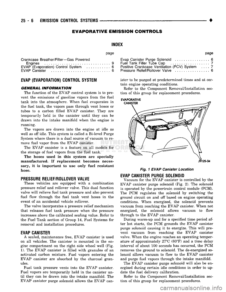
A sealed, maintenance free, EVAP canister
is
used
on
all
vehicles.
The
canister
is
mounted
in the en
gine compartment
on the
right side wheel well
(Fig.
1).
The
EVAP canister
is
filled with granules
of an
activated carbon mixture. Fuel vapors entering
the
EVAP canister
are
absorbed
by the
charcoal gran
ules.
Fuel tank pressure vents into
the
EVAP canister.
Fuel vapors
are
temporarily held
in the
canister
un
til they
can be
drawn into
the
intake manifold.
The
EVAP canister purge solenoid allows
the
EVAP can ister
to be
purged
at
predetermined times
and at
cer
tain engine operating conditions.
Refer
to the
Component Removal/Installation sec
tion
of
this group
for
replacement procedures.
EVAPORATIVE
Fig.
1
EVAP
Canister Location
EVAP CANISTER PURGE SOLENOID
Vacuum
for the
EVAP canister
is
controlled
by the
EVAP canister purge solenoid
(Fig. 2). The
solenoid
is operated
by the
powertrain control module (PCM).
The
PCM
regulates
the
solenoid
by
switching
the
ground circuit
on and off
based
on
engine operating conditions. When energized,
the
solenoid prevents
vacuum from reaching
the
EVAP canister. When
not
energized,
the
solenoid allows vacuum
to
flow
through
to the
EVAP canister. During warm-up
and for a
specified time period
af
ter
hot
starts,
the PCM
grounds
the
EVAP canister purge solenoid causing
it to
energize. This will pre
vent vacuum from reaching
the
EVAP canister
valve. When
the
engine reaches
an
operating temper ature
of
approximately 27°C (80°F)
and a
time delay
interval
of
about
100
seconds
has
occurred,
the PCM
removes
the
ground
to
solenoid.
The
de-energized
so
lenoid allows vacuum
to
flow
to the
EVAP canister and purge fuel vapors through
the
intake manifold. The EVAP canister purge solenoid will also
be en
ergized during certain idle conditions
in
order
to up
date
the
fuel delivery calibration. Refer
to the
Component Removal/Installation sec
tion
of
this group
for
replacement procedures.