1993 DODGE TRUCK wheel
[x] Cancel search: wheelPage 1375 of 1502
22 - e
WHEELS
AND
TIRES
• WHEELS
GENERAL
INFORMATION
Original equipment wheels are designed for all
loads up to the specified Maximum Vehicle Capacity. All models use steel or cast aluminum drop center
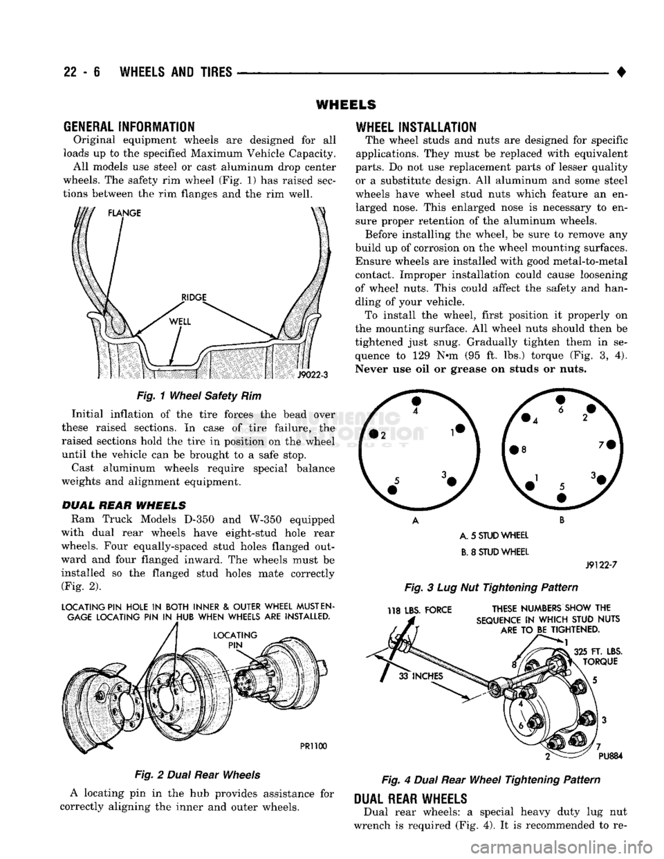
wheels. The safety rim wheel (Fig. 1) has raised sec
tions between the rim flanges and the rim well.
S
J9022-3
Fig.
1
Wheel
Safety Rim Initial inflation of the tire forces the bead over
these raised sections. In case of tire failure, the
raised sections hold the tire in position on the wheel
until the vehicle can be brought to a safe stop.
Cast aluminum wheels require special balance
weights and alignment equipment.
DUAL
REAR
WHEELS
Ram Truck Models
D-350
and
W-350
equipped
with dual rear wheels have eight-stud hole rear
wheels. Four equally-spaced stud holes flanged out
ward and four flanged inward. The wheels must be
installed so the flanged stud holes mate correctly (Fig. 2).
LOCATING PIN HOLE
IN
BOTH INNER
&
OUTER WHEEL
MUST
EN
GAGE
LOCATING PIN
IN
HUB WHEN WHEELS ARE INSTALLED.
PR1100
Fig.
2
Dual
Rear
Wheels
A locating pin in the hub provides assistance for
correctly aligning the inner and outer wheels.
WHEEL
INSTALLATION
The wheel studs and nuts are designed for specific
applications. They must be replaced with equivalent
parts.
Do not use replacement parts of lesser quality or a substitute design. All aluminum and some steel
wheels have wheel stud nuts which feature an en larged nose. This enlarged nose is necessary to en
sure proper retention of the aluminum wheels. Before installing the wheel, be sure to remove any
build up of corrosion on the wheel mounting surfaces. Ensure wheels are installed with good metal-to-metal contact. Improper installation could cause loosening
of wheel nuts. This could affect the safety and han
dling of your vehicle. To install the wheel, first position it properly on
the mounting surface. All wheel nuts should then be
tightened just snug. Gradually tighten them in se
quence to 129 N-m (95 ft. lbs.) torque (Fig. 3, 4).
Never use oil or grease on studs or nuts.
A. 5
STUD
WHEEL
B.
8
STUD
WHEEL
J9122-7
Fig.
3 Lug Nut Tightening
Pattern
118 LBS. FORCE THESE NUMBERS SHOW THE
SEQUENCE
IN
WHICH STUD NUTS
ARE
TO BE TIGHTENED.
FT. LBS.
TORQUE PU884
Fig.
4
Dual
Rear
Wheel
Tightening
Pattern
DUAL
REAR WHEELS
Dual rear wheels: a special heavy duty lug nut
wrench is required (Fig. 4). It is recommended to re-
Page 1376 of 1502
•
WHEELS
AND
TIRES
22 - 7 move and install dual rear wheels only when the
proper wrench is available.
INSTALLATION
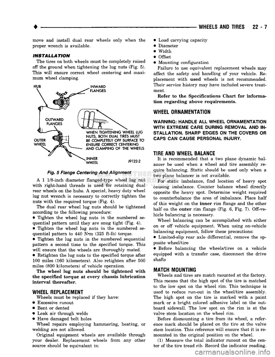
The tires on both wheels must be completely raised
off the ground when tightening the lug nuts (Fig. 5).
This will ensure correct wheel centering and maxi mum wheel clamping.
HUB
^
INWARD
Fig.
5 Flange Centering And
Alignment
A 1
1/8-inch
diameter flanged-type wheel lug nut
with right-hand threads is used for retaining dual rear wheels on the hubs. A special, heavy duty wheel lug nut wrench is necessary to correctly tighten the nuts with the required torque (Fig. 4).
The dual rear wheel lug nuts should be tightened
according to the following procedure:
• Tighten the wheel lug nuts in the numbered se
quential pattern until they are snug tight (Fig. 4).
• Tighten the wheel lug nuts in the numbered se
quential pattern to 440 N#m (325 ft-lb) torque.
• Tighten the lug nuts in the numbered sequential
pattern a second time to the specified torque. This will ensure that the wheels are thoroughly mated. • Retighten the lug nuts to the specified torque after 100 miles (160 kilometers). Also retighten after 500
miles (800 kilometers) of vehicle operation.
The wheel lug nuts should be tightened with
the specified torque at every chassis lubrication
interval thereafter.
WHEEL REPLACEMENT
Wheels must be replaced if they have:
• Excessive runout
• Bent or dented
• Leak air through welds
• Have damaged bolt holes Wheel repairs employing hammering, heating, or
welding are not allowed. Original equipment wheels are available through
your dealer. Replacement wheels from any other source should be equivalent in: • Load carrying capacity
• Diameter
® Width
• Offset
• Mounting configuration
Failure to use equivalent replacement wheels may
affect the safety and handling of your vehicle. Re
placement with used wheels is not recommended.
Their service history may have included severe treat ment.
Refer to the Specifications Chart for informa
tion regarding above requirements.
WHEEL ORNAMENTATION
WARNING; HANDLE
ALL
WHEEL ORNAMENTATION
WITH
EXTREME CARE DURING REMOVAL
AND IN
STALLATION. SHARP EDGES
ON THE
COVERS
OR
CAPS
CAN
CAUSE PERSONAL INJURY.
TIRE AND WHEEL BALANCE
It is recommended that a two plane dynamic bal
ancer be used when a wheel and tire assembly re
quire balancing. Static should be used only when a
two plane balancer is not available. For static imbalance, find location of heavy spot
causing imbalance. Counter balance wheel directly
opposite the heavy spot. Determine weight required
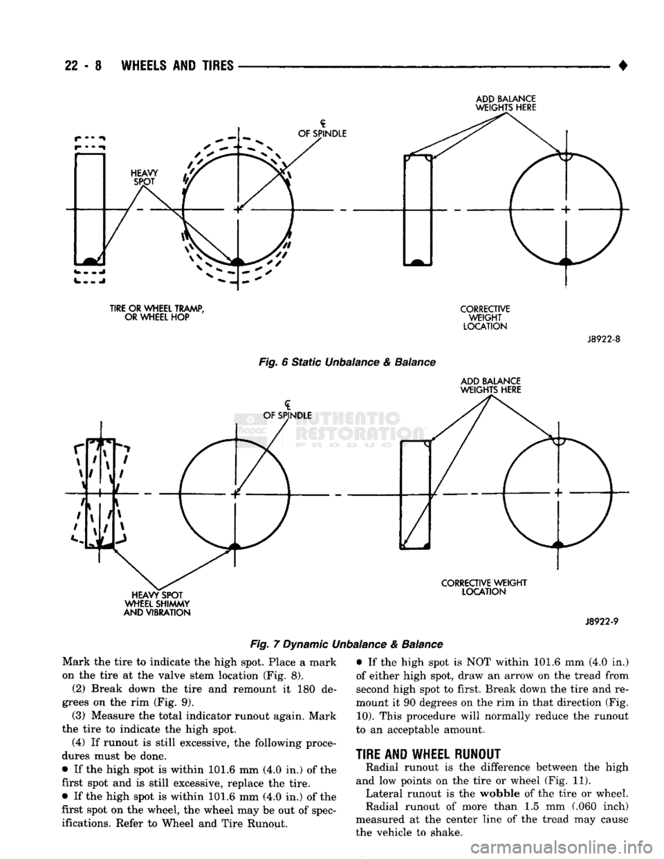
to counterbalance the area of imbalance. Place half of this weight on the inner rim flange and the other
half on the outer rim flange (Fig. 6, Fig. 7). Off-ve
hicle balancing is necessary. Wheel balancing can be accomplished with either
on or off vehicle equipment. When using on-vehicle
balancing equipment, follow these precautions: • Limited-slip rear axle differential, remove the op
posite wheel/tire • Before balancing the wheels/tires on a vehicle
equipped with a transfer case, disconnect the drive shafts
MATCH
MOUNTING
Wheels and tires are match mounted at the factory.
This means that the high spot of the tire is matched
to the low spot on the wheel rim. This technique is used to reduce run-out in the wheel/tire assembly.
The high spot on the tire is marked with a paint mark or a bright colored adhesive label on the out
board sidewall. The low spot on the rim is at the
valve stem location on the wheel rim. Before dismounting a tire from its wheel, a refer
ence mark should be placed on the tire at the valve stem location. This reference will ensure that it is re
mounted in the original position on the wheel. (1) Measure the total indicator runout on the cen
ter of the tire tread rib. Record the indicator reading.
Page 1377 of 1502
22 - 8
WHEELS
AND
TIRES
•
ADP
BALANCE
WEIGHTS
HERE
TIRE
OR
WHEEL TRAMP,
OR WHEEL
HOP Fig. 6 Static Unbalance & Balance
CORRECTIVE
WEIGHT
LOCATION ADD BALANCE
WEIGHTS HERE
J8922-8
HEAVY SPOT
WHEEL SHIMMY
AND VIBRATION
CORRECTIVE
WEIGHT
LOCATION
J8922-9
Fig. 7 Dynamic Unbalance & Balance
Mark the tire to indicate the high spot. Place a mark
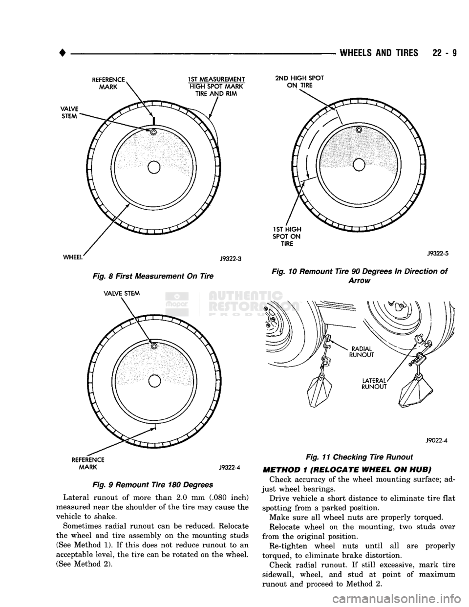
on the tire at the valve stem location (Fig. 8). (2) Break down the tire and remount it 180 de
grees on the rim (Fig. 9).
(3)
Measure the total indicator runout again. Mark
the tire to indicate the high spot. (4) If runout is still excessive, the following proce
dures must be done.
• If the high spot is within 101.6 mm (4.0 in.) of the
first spot and is still excessive, replace the tire.
• If the high spot is within 101.6 mm (4.0 in.) of the
first spot on the wheel, the wheel may be out of spec
ifications. Refer to Wheel and Tire Runout. • If the high spot is NOT within 101.6 mm (4.0 in.)
of either high spot, draw an arrow on the tread from
second high spot to first. Break down the tire and re
mount it 90 degrees on the rim in that direction (Fig.
10).
This procedure will normally reduce the runout
to an acceptable amount.
TIRE
AND WHEEL RUNOUT
Radial runout is the difference between the high
and low points on the tire or wheel (Fig. 11). Lateral runout is the wobble of the tire or wheel.
Radial runout of more than 1.5 mm (.060 inch)
measured at the center line of the tread may cause
the vehicle to shake.
Page 1378 of 1502
•
WHEELS
AND
TIRES
22 - 9
Fig.
8 First Measurement On
Tire
VALVE STEM
REFERENCE
AAARK J9322-4
Fig.
9
Remount
Tire
180
Degrees
Lateral runout of more than 2.0 mm (.080 inch)
measured near the shoulder of the tire may cause the
vehicle to shake.
Sometimes radial runout can be reduced. Relocate
the wheel and tire assembly on the mounting studs (See Method 1). If this does not reduce runout to an
acceptable level, the tire can be rotated on the wheel. (See Method 2). 2ND HIGH SPOT
ON TIRE
SPOT ON TIRE J9322-5
Fig.
10
Remount
Tire
90
Degrees
In Direction of
Arrow
J9022-4
Fig.
11
Checking
Tire
Runout
METHOD
1
(RELOCATE WHEEL
ON HUB) Check accuracy of the wheel mounting surface; ad
just wheel bearings.
Drive vehicle a short distance to eliminate tire flat
spotting from a parked position. Make sure all wheel nuts are properly torqued.
Relocate wheel on the mounting, two studs over
from the original position.
Re-tighten wheel nuts until all are properly
torqued, to eliminate brake distortion.
Check radial runout. If still excessive, mark tire
sidewall, wheel, and stud at point of maximum
runout and proceed to Method 2.
Page 1379 of 1502
22
- 10
WHEELS
AND
TIRES
•
J8922-11
Fig.
12
Checking
Wheel
Runout
METHOD
2
(RELOCATE
TIRE
ON
WHEEL)
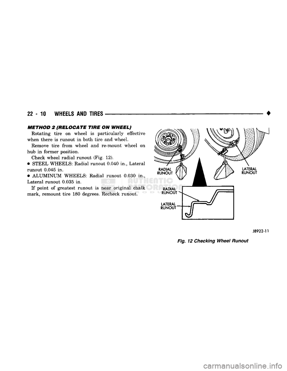
Rotating tire on wheel is particularly effective
when there is runout in both tire and wheel. Remove tire from wheel and re-mount wheel on
hub in former position. Check wheel radial runout (Fig. 12).
• STEEL WHEELS: Radial runout 0.040 in., Lateral
runout 0.045 in. • ALUMINUM WHEELS: Radial runout 0.030 in.,
Lateral runout 0.035 in.
If point of greatest runout is near original chalk
mark, remount tire 180 degrees. Recheck runout.
Page 1380 of 1502
•
WHEELS
AND
TIRES
22-11 VEHICLE VIBRATION
Vehicle vibration can
be
caused by:
• Tire/wheel unbalance
or
excessive runout
• Defective tires with extreme tread wear
• Nylon overlay flat spots (performance tires only)
• Incorrect wheel bearing adjustment
(if
applicable)
• Loose
or
worn suspension/steering components
• Certain tire tread patterns
• Incorrect drive shaft angles
or
excessive drive
shaft/yoke runout
• Defective
or
worn U-joints
• Excessive brake rotor
or
drum runout
• Loose engine
or
transmission supports/mounts
• And
by
engine operated accessories Refer
to the
appropriate Groups
in
this man
ual for additional information.
VIBRATION
TYPES
There are two types
of
vehicle vibration:
• Mechanical
• Audible. Mechanical vehicle vibration
can be
felt through
the seats, floor pan and/or steering wheel. Audible vehicle vibration
is
heard above normal
background noise.
The
sound
can be a
droning
or
drumming noise. Vibrations
are
sensitive
to
change
in
engine
torque, vehicle speed
or
engine speed.
ENGINE TORQUE SENSITIVE VIBRATION
This vibration can
be
increased
or
decreased by:
• Accelerating
• Decelerating
• Coasting
• Maintaining
a
constant vehicle speed
VEHICLE SPEED SENSITIVE VIBRATION
This vibration condition always occurs
at
the same
vehicle speed regardless
of
the engine torque
or en
gine speed.
ENGINE SPEED
{RPM}
SENSITIVE VIBRATION
This vibration occurs
at
varying engine speeds.
It
can
be
isolated
by
increasing
or
decreasing
the en
gine speed with the transmission
in
NEUTRAL posi
tion.
VIBRATION
DIAGNOSIS
A vibration diagnosis should always begin with
a
10 mile (16 km) trip (to warm the vehicle and tires).
Then
a
road test
to
identify the vibration. Corrective action should
not be
attempted until
the
vibration
type has been identified
via a
road test. During the road test, drive the vehicle
on a
smooth
surface.
If
vibration exists, note
and
record
the
fol
lowing information: • Identify
the
vehicle speed range when
the
vibra
tion occurs
• Identify the type
of
vibration
• Identify the vibration sensitivity
• Determine
if
the vibration
is
affected
by
changes
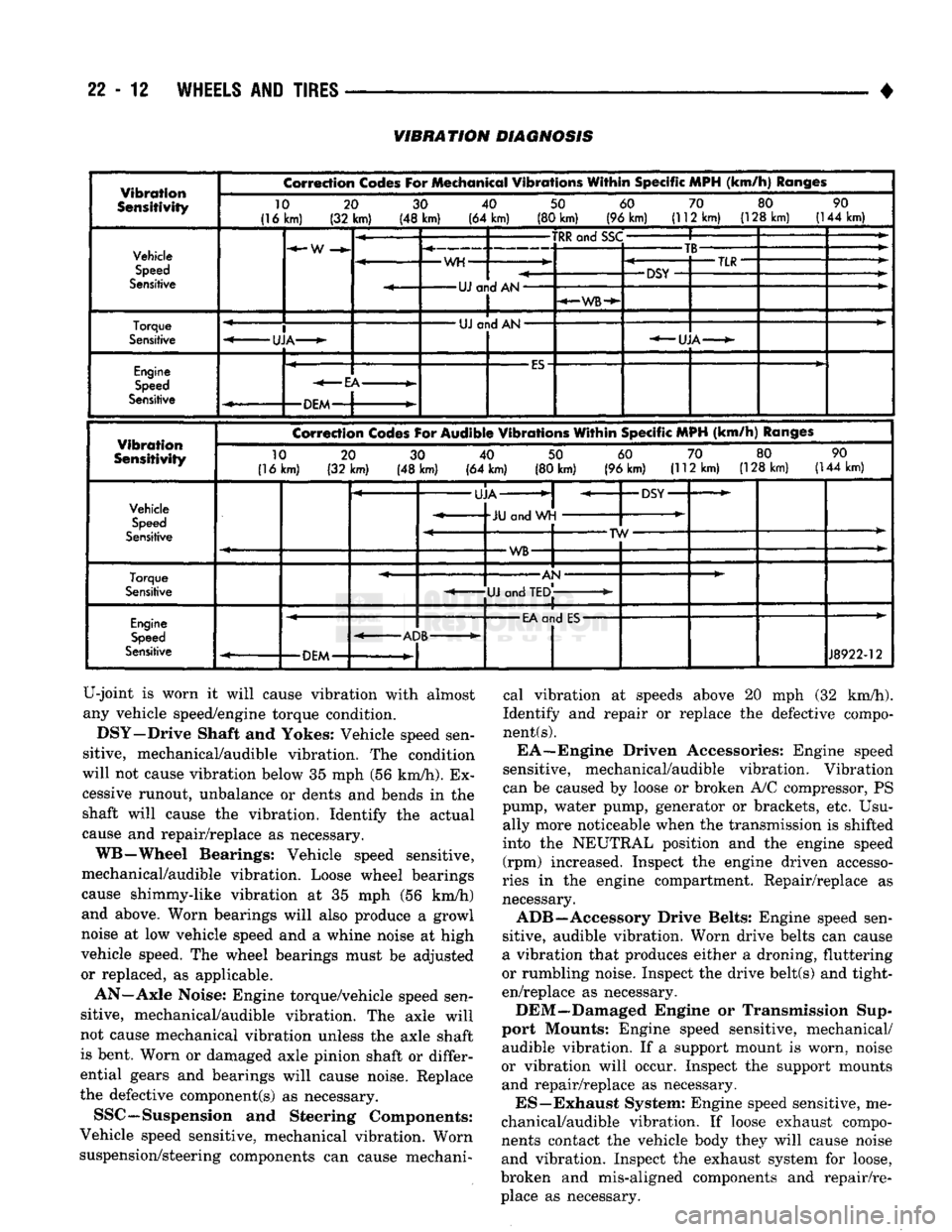
in vehicle speed, engine speed and engine torque. When the vibration has been identified, refer to the
Vibration Diagnosis chart
for
causes. Consider cor
recting only those causes coded
in
the chart that
are
related
to
the vibration condition.
Refer
to
the following cause codes and descriptions
for explanations when referring
to
the chart.
TRR—Tire
and
Wheel Radial Runout: Vehicle
speed sensitive, mechanical vibration.
The
runout
will not cause vibration below
20
mph (32 km/h).
WH—Wheel Hop: Vehicle speed sensitive,
me
chanical vibration.
The
wheel
hop
generates rapid
up-down movement
in
the steering wheel. The vibra
tion
is
most noticeable
in the 20 - 40
mph
(32 - 64
km/h) range. The wheel hop will not cause vibration
below
20
mph (32 km/h). Wheel hop
is
caused
by a
tire/wheel that
has a
radial runout
of
more than 0.045 of-an-inch (1.14 mm).
If
wheel runout
is
accept
able
and
combined runout cannot
be
reduced
by re
positioning the tire
on
wheel, replace tire.
TB—Tire/Wheel Balance: Vehicle speed sensitive,
mechanical vibration. Static tire/wheel unbalance
will not cause vibration below 30 mph (46 km/h). Dy
namic tire/wheel unbalance will
not
cause vibration
below
40
mph (64 km/h). TLR—Tire/Wheel Lateral runout: Vehicle speed
sensitive, mechanical vibration. The runout will
not
cause vibration below
50 - 55 mph (80 - 88
km/h).
Excessive lateral runout will also cause front-end shimmy. TW—Tire Wear: Vehicle speed sensitive, audible
vibration. Abnormal tire wear causes small vibration in
the 30 - 55
mph
(88
km/h) range. This will pro
duce
a
whine noise
at
high speed.
The
whine will
change
to a
growl noise when the speed
is
reduced. W—Tire Waddle: Vehicle speed sensitive, mechan
ical vibration. Irregular tire uniformity
can
cause
side-to-side motion during speeds
up to 15
mph
(24
km/h).
If
the motion
is
excessive, identify
the
defec
tive tire and replace
it.
U A J—Universal Joint (Drive Shaft) Angles:
Torque/vehicle speed sensitive, mechanical/audible
vibration. Incorrect drive shaft angles cause mechan ical vibration below
20
mph (32 km/h) and
in
the
70
mph (112 km/h) range. The incorrect angles can also
produce
an
audible vibration
in
the 20
-
50 mph (32
-
80 km/h) range. Caster adjustment could
be
required
to correct the angles. UJ—Universal Joints: Engine torque/vehicle
speed sensitive, mechanical/audible vibration.
If
the
Page 1381 of 1502
22-12
WHEELS
AND
TIRES
VIBRATION
DIAGNOSIS
Vibration
Sensitivity
Correction
Codes
For
Mechanical
Vibrations
Within
Specific
MPH
(km/h)
Ranges
10
(16km)
20
(32 km) 30
(48 km) 40
(64 km) 50
(80 km) 60
(96 km) 70
(112 km) 80
(128 km) 90
(144 km) Vehicle
Speed
Sensitive
•W
-WH-
-TRR
and
SSC-
-UJ
and AN-
-WB-
-TB-
-DSY
•TLR-
Torque
Sensitive
I
-UJA-
•
UJ
and AN
•
•UJA-
Engine
Speed
Sensitive
•ES
•EA-
•DEM-
Vibration
Sensitivity
Correction
Codes
For
Audible
Vibrations
Within
Specific
MPH
(km/h)
Ranges
10
(16 km) 20
(32 km) 30
(48 km) 40
(64 km) 50
(80 km) 60
(96 km) 70
(112 km) 80
(128 km) 90
(144 km)
Vehicle
Speed
Sensitive
•UJA-
JU
and WH
•DSY"
-TW-
•WB-
Torque
Sensitive
-AN
*
-UJ
and
TED,
Engine
Speed
Sensitive
•
EA
and
ES-
-ADB-
-DEM-
J8922-12
U-joint is worn it will cause vibration with almost
any vehicle speed/engine torque condition. DSY—Drive Shaft and Yokes: Vehicle speed sen
sitive, mechanical/audible vibration. The condition
will not cause vibration below 35 mph (56 km/h). Ex
cessive runout, unbalance or dents and bends in the shaft will cause the vibration. Identify the actual
cause and repair/replace as necessary.
WB—Wheel Bearings: Vehicle speed sensitive,
mechanical/audible vibration. Loose wheel bearings
cause shimmy-like vibration at 35 mph (56 km/h)
and above. Worn bearings will also produce a growl
noise at low vehicle speed and a whine noise at high
vehicle speed. The wheel bearings must be adjusted
or replaced, as applicable.
AN—Axle Noise: Engine torque/vehicle speed sen
sitive, mechanical/audible vibration. The axle will
not cause mechanical vibration unless the axle shaft
is bent. Worn or damaged axle pinion shaft or differ
ential gears and bearings will cause noise. Replace
the defective component(s) as necessary.
SSC—Suspension and Steering Components:
Vehicle speed sensitive, mechanical vibration. Worn
suspension/steering components can cause mechani cal vibration at speeds above 20 mph (32 km/h).
Identify and repair or replace the defective compo
nent
(s).
EA—Engine Driven Accessories: Engine speed
sensitive, mechanical/audible vibration. Vibration
can be caused by loose or broken A/C compressor, PS
pump, water pump, generator or brackets, etc. Usu ally more noticeable when the transmission is shifted
into the NEUTRAL position and the engine speed (rpm) increased. Inspect the engine driven accesso
ries in the engine compartment. Repair/replace as
necessary.
ADB—Accessory Drive Belts: Engine speed sen
sitive, audible vibration. Worn drive belts can cause
a vibration that produces either a droning, fluttering
or rumbling noise. Inspect the drive belt(s) and tight
en/replace as necessary.
DEM—Damaged Engine or Transmission Sup
port Mounts: Engine speed sensitive, mechanical/ audible vibration. If a support mount is worn, noise
or vibration will occur. Inspect the support mounts and repair/replace as necessary.
ES—Exhaust System: Engine speed sensitive, me
chanical/audible vibration. If loose exhaust compo
nents contact the vehicle body they will cause noise
and vibration. Inspect the exhaust system for loose,
broken and mis-aligned components and repair/re place as necessary.
Page 1382 of 1502
•
WHEELS
AND
TIRES
22 - 13
LUG
NUT
TORQUE
DESCRIPTION
1/2x20
with
60°
Cone 15 Inch Wheel
1/2x20
with
90°
Cone 16 Inch Single Wheel
5/8x18
with
90°
Cone 16 Inch Single Wheel
5/8x18
with Flanged
Nut..
16 Inch Dual Wheel
TORQUE
109
to 150
N-m
(80 to 110 ft.
lbs.)
115
to
155 N-m
(85 to 115
ft. lbs.)
240 to 305 N-m
(175 to
225 ft. lbs.)
410 to 475 N-m
(300 to
350 ft. lbs.)
J9322-9
TORQUE SPECIFICATIONS