1993 DODGE TRUCK battery
[x] Cancel search: batteryPage 295 of 1502
7 - 24
COOLING SYSTEM
• If the thermostat is being replaced, be sure that
the replacement is the specified thermostat for the vehicle model and engine type. Factory installed thermostat housings on 3.9L/5.2L/
5.9L engines are installed on a gasket with an anti-
stick coating. This will aid in gasket removal and
clean-up.
(1) Disconnect negative battery cable at battery.
(2) Drain cooling system until coolant level is be
low thermostat. Refer to Draining Cooling System in
this group. If not equipped with air conditioning, pro ceed to step number 4.
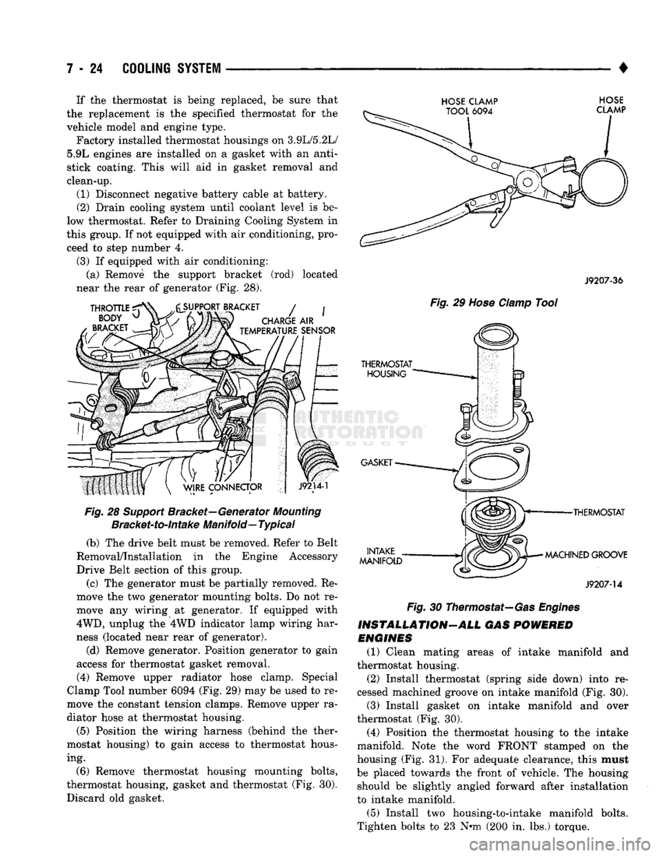
(3) If equipped with air conditioning: (a) Remove the support bracket (rod) located
near the rear of generator (Fig. 28).
Fig.
28
Support
Bracket—Generator
Mounting
Bracket-to-intake
Manifold—
Typical
(b) The drive belt must be removed. Refer to Belt
Removal/Installation in the Engine Accessory
Drive Belt section of this group.
(c) The generator must be partially removed. Re
move the two generator mounting bolts. Do not re
move any wiring at generator. If equipped with
4WD,
unplug the 4WD indicator lamp wiring har
ness (located near rear of generator).
(d) Remove generator. Position generator to gain
access for thermostat gasket removal.
(4) Remove upper radiator hose clamp. Special
Clamp Tool number 6094 (Fig. 29) may be used to re
move the constant tension clamps. Remove upper ra
diator hose at thermostat housing.
(5) Position the wiring harness (behind the ther
mostat housing) to gain access to thermostat hous ing.
(6) Remove thermostat housing mounting bolts,
thermostat housing, gasket and thermostat (Fig. 30). Discard old gasket.
HOSE CLAMP HOSE
J9207-36
Fig.
29
Hose
Clamp
Tool
•THERMOSTAT
MACHINED GROOVE
J9207-14
Fig.
30 Thermostat—Gas
Engines
INSTALLATION-ALL GAS
POWERED
ENGINES
(1) Clean mating areas of intake manifold and
thermostat housing. (2) Install thermostat (spring side down) into re
cessed machined groove on intake manifold (Fig. 30).
(3) Install gasket on intake manifold and over
thermostat (Fig. 30).
(4) Position the thermostat housing to the intake
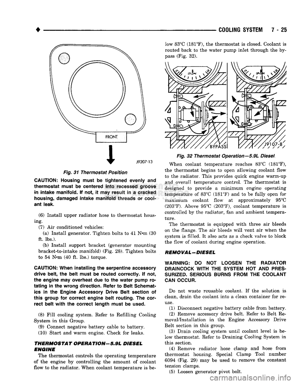
manifold. Note the word FRONT stamped on the
housing (Fig. 31). For adequate clearance, this must
be placed towards the front of vehicle. The housing should be slightly angled forward after installation
to intake manifold.
(5) Install two housing-to-intake manifold bolts.
Tighten bolts to 23 N-m (200 in. lbs.) torque.
Page 296 of 1502
•
COOLING
SYSTEM
7 - 25
Fig.
31 Thermostat Position
CAUTION; Housing must
be
tightened
evenly and
thermostat must
be
centered into recessed groove in
intake manifold. If not, it may
result
in a
cracked
housing,
damaged intake manifold threads
or
cool
ant
leak.
(6) Install upper radiator hose to thermostat hous
ing. (7) Air conditioned vehicles: (a) Install generator. Tighten bolts to 41 N-m (30
ft. lbs.). (b) Install support bracket (generator mounting
bracket-to-intake manifold) (Fig. 28). Tighten bolts
to 54 N-m (40 ft. lbs.) torque.
CAUTION:
When installing
the
serpentine accessory
drive belt,
the
belt must
be
routed correctly.
If not,
the engine
may overheat due to the
water pump
ro
tating in the
wrong direction. Refer
to
Belt Schemat
ics
in the
Engine
Accessory
Drive Belt section
of
this group
for
correct engine belt routing.
The
cor rect belt with
the
correct length must
be
used.
(8) Fill cooling system. Refer to Refilling Cooling
System in this Group. (9) Connect negative battery cable to battery.
(10) Start and warm engine. Check for leaks.
THERMOSTAT OPERATIONr-5.9L DIESEL
ENGINE
The thermostat controls the operating temperature
of the engine by controlling the amount of coolant
flow to the radiator. When coolant temperature is be low 83°C (181°F), the thermostat is closed. Coolant is
routed back to the water pump inlet through the by
pass (Fig. 32).
Fig.
32 Thermostat Operation—5.9L
Diesel
When coolant temperature reaches 83°C (181°F),
the thermostat begins to open allowing coolant flow
to the radiator. This provides quick engine warm-up and overall temperature control. The thermostat is
designed to provide a minimum engine operating
temperature of 83°C (181°F) and to be fully open for maximum coolant flow at approximately 95°C (203°F). Above 95°C (203°F), coolant temperature is
controlled by the radiator, fan and ambient tempera
ture.
The thermostat is equipped with three air bleeds
on the flange. The air bleeds will vent air when the system is filled. It also acts as a check valve to block
the flow of coolant during engine operation.
REMOVAL-DIESEL
WARNING:
DO NOT
LOOSEN
THE
RADIATOR
DRAINCOCK
WITH
THE
SYSTEM
HOT
AND
PRES
SURIZED.
SERIOUS
BURNS
FROM
THE
COOLANT
CAN
OCCUR.
Do not waste reusable coolant. If the solution is
clean, drain the coolant into a clean container for re
use.
(1) Disconnect negative battery cable from battery.
(2) Remove accessory drive belt. Refer to Belt Re
moval/Installation in the Engine Accessory Drive
Belt section in this group.
(3) Drain cooling system until coolant level is be
low thermostat. Refer to Draining Cooling System in
this section.
(4) Remove radiator hose clamp and hose from
thermostat housing. Special Clamp Tool number 6094 (Fig. 29) may be used to remove the constant
tension clamps.
(5) Loosen generator pivot bolt.
Page 297 of 1502
7 - 26
COOLING
SYSTEM
————
Fig. 33 Generator
Mounting
Bolts—5.9L
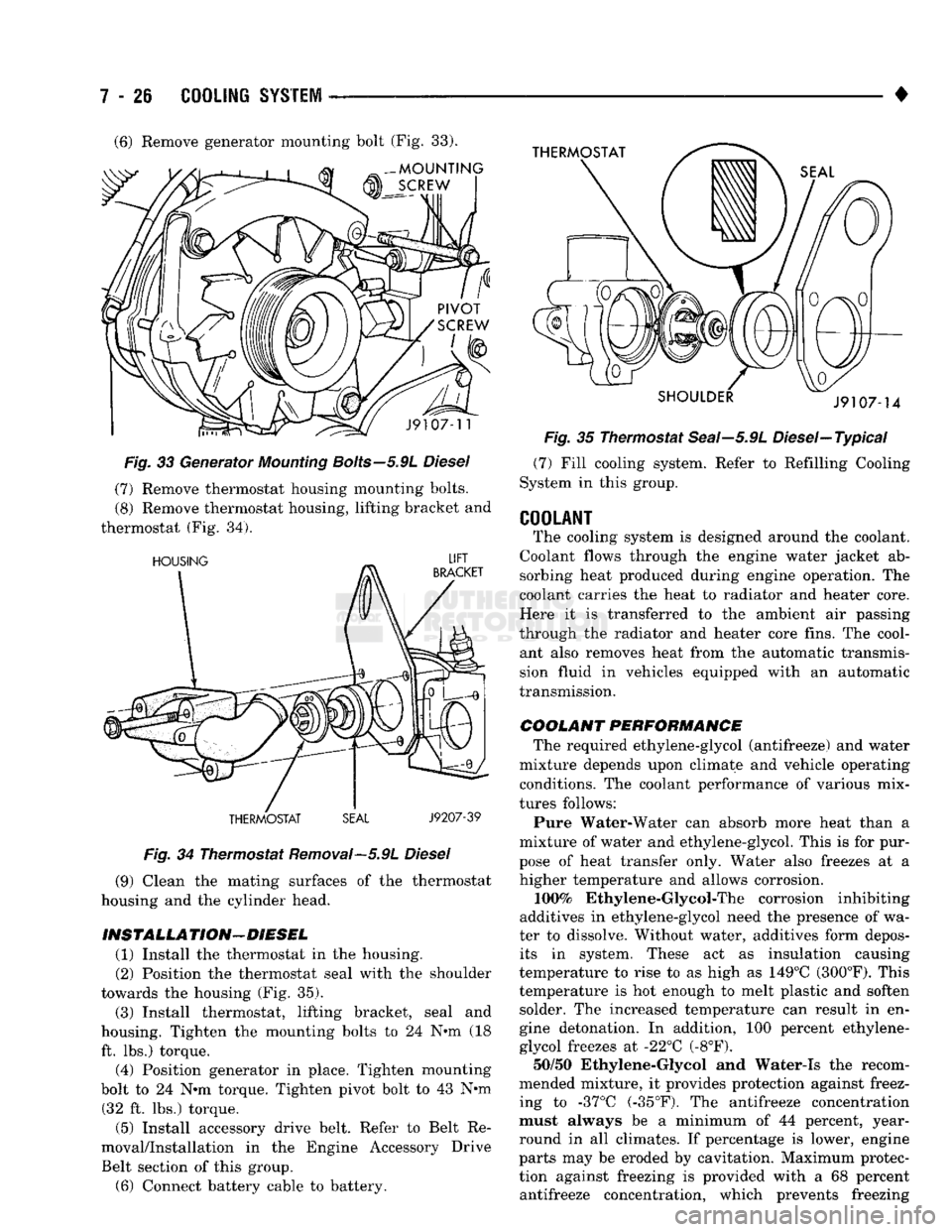
Diesel (7) Remove thermostat housing mounting bolts.
(8) Remove thermostat housing, lifting bracket and
thermostat (Fig. 34).
Fig.
34 Thermostat Removal—5.9L
Diesel
(9) Clean the mating surfaces of the thermostat
housing and the cylinder head.
INSTALLA TION—DIESEL (1) Install the thermostat in the housing.
(2) Position the thermostat seal with the shoulder
towards the housing (Fig. 35).
(3) Install thermostat, lifting bracket, seal and
housing. Tighten the mounting bolts to 24 N°m (18 ft. lbs.) torque. (4) Position generator in place. Tighten mounting
bolt to 24 N*m torque. Tighten pivot bolt to 43 N*m (32 ft. lbs.) torque.
(5) Install accessory drive belt. Refer to Belt Re
moval/Installation in the Engine Accessory Drive
Belt section of this group.
(6) Connect battery cable to battery. •
Fig.
35 Thermostat Seai—5.9L Diesel—Typical (7) Fill cooling system. Refer to Refilling Cooling
System in this group.
COOLANT
The cooling system is designed around the coolant.
Coolant flows through the engine water jacket ab sorbing heat produced during engine operation. The
coolant carries the heat to radiator and heater core.
Here it is transferred to the ambient air passing
through the radiator and heater core fins. The cool ant also removes heat from the automatic transmission fluid in vehicles equipped with an automatic
transmission.
COOLANT PERFORMANCE The required ethylene-glycol (antifreeze) and water
mixture depends upon climate and vehicle operating conditions. The coolant performance of various mix
tures follows:
Pure Water-Water can absorb more heat than a
mixture of water and ethylene-glycol. This is for pur
pose of heat transfer only. Water also freezes at a higher temperature and allows corrosion.
100%
Ethylene-Glycol-The corrosion inhibiting
additives in ethylene-glycol need the presence of wa
ter to dissolve. Without water, additives form depos its in system. These act as insulation causing
temperature to rise to as high as 149°C (300°F). This
temperature is hot enough to melt plastic and soften solder. The increased temperature can result in en
gine detonation. In addition, 100 percent ethylene-
glycol freezes at -22°C (-8°F). 50/50 Ethylene-Glycol and Water-Is the recom
mended mixture, it provides protection against freez
ing to -37°C (-35°F). The antifreeze concentration
must always be a minimum of 44 percent, year-
round in all climates. If percentage is lower, engine
parts may be eroded by cavitation. Maximum protec
tion against freezing is provided with a 68 percent antifreeze concentration, which prevents freezing (6) Remove generator mounting bolt (Fig. 33).
Page 304 of 1502
•
COOLING
SYSTEM
7 - 33 The radiator supplies sufficient heat transfer to
cool the engine and automatic transmission (if equipped).
RADIATOR COOLANT FLOW CHECK
Use the following procedure to determine if coolant
is flowing through the cooling system.
(1) Idle engine until operating temperature is
reached. If the upper radiator hose is warm to the
touch, the thermostat is opening and coolant is flow ing to the radiator.
WARNING:
HOT,
PRESSURIZED COOLANT
CAN
CAUSE
INJURY
BY
SCALDING. USING
A
RAG
TO
COVER
THE
RADIATOR
PRESSURE
CAP,
OPEN RADIATOR
CAP
SLOWLY
TO THE
FIRST STOP.
THIS
WILL
ALLOW
ANY
BUILT-UP
PRESSURE
TO
VENT
TO
THE
RESERVE/OVERFLOW TANK. AFTER
PRESSURE
BUILD-UP
HAS
BEEN RELEASED,
RE
MOVE
CAP
FROM FILLER NECK.
(2) Drain a small amount of coolant from the radi
ator until the ends of the radiator tubes are visible
through the filler neck. Idle the engine at normal op
erating temperature. If coolant is flowing past the
exposed tubes, the coolant is circulating.
RADIATOR REMOVAL-EXCEPT DIESEL
(1) Disconnect negative battery cable from battery.
WARNING;
DO NOT
REMOVE
THE
CYLINDER BLOCK DRAIN PLUGS
OR
LOOSEN
THE
RADIATOR
DRAINCOCK
WITH
THE
SYSTEM
HOT AND
UNDER
PRESSURE.
SERIOUS BURNS FROM COOLANT
CAN OCCUR.
(2) Drain the cooling system. Refer to Draining
Cooling System.
(3) Disconnect throttle cable from clip at radiator
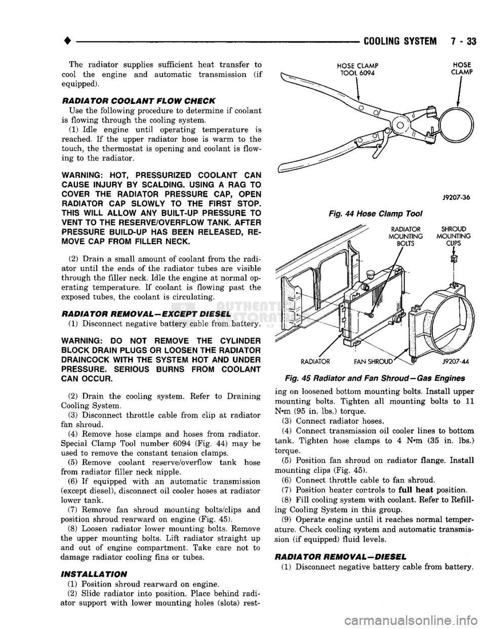
fan shroud. (4) Remove hose clamps and hoses from radiator.
Special Clamp Tool number 6094 (Fig. 44) may be
used to remove the constant tension clamps.
(5) Remove coolant reserve/overflow tank hose
from radiator filler neck nipple.
(6) If equipped with an automatic transmission
(except diesel), disconnect oil cooler hoses at radiator
lower tank.
(7) Remove fan shroud mounting bolts/clips and
position shroud rearward on engine (Fig. 45). (8) Loosen radiator lower mounting bolts. Remove
the upper mounting bolts. Lift radiator straight up and out of engine compartment. Take care not to
damage radiator cooling fins or tubes.
INSTALLATION
(1) Position shroud rearward on engine.
(2) Slide radiator into position. Place behind radi
ator support with lower mounting holes (slots) rest-
HOSE
CLAMP
TOOL
6094
HOSE
CLAMP
J9207-36
Fig.
44
Hose
Clamp
Tool
RADIATOR SHROUD
MOUNTING MOUNTING
BOLTS
CUPS
RADIATOR
V1
FAN SHROUD^
J9207-44
Fig.
45 Radiator and Fan
Shroud—Gas Engines
ing on loosened bottom mounting bolts. Install upper
mounting bolts. Tighten all mounting bolts to 11
N*m (95 in. lbs.) torque.
(3) Connect radiator hoses.
(4) Connect transmission oil cooler lines to bottom
tank. Tighten hose clamps to 4 N#m (35 in. lbs.)
torque.
(5) Position fan shroud on radiator flange. Install
mounting clips (Fig. 45).
(6) Connect throttle cable to fan shroud.
(7) Position heater controls to full heat position.
(8) Fill cooling system with coolant. Refer to Refill
ing Cooling System in this group.
(9) Operate engine until it reaches normal temper
ature. Check cooling system and automatic transmis
sion (if equipped) fluid levels.
RADIATOR REMOVAL-DIESEL
(1) Disconnect negative battery cable from battery.
Page 306 of 1502
•
COOLING
SYSTEM
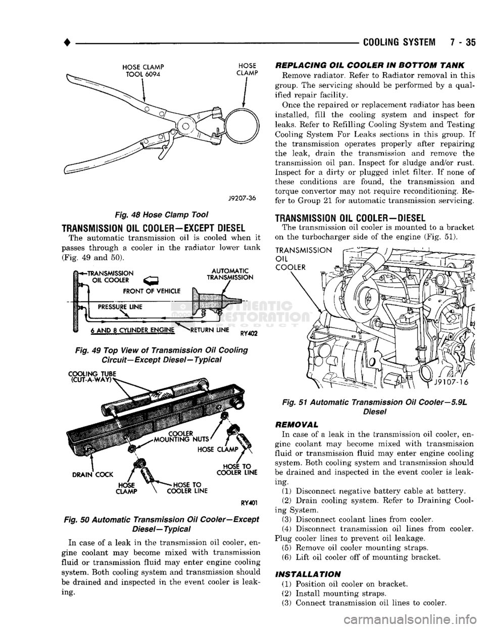
7 - 35
HOSE
CLAMP TOOL
6094
HOSE
CLAMP
J9207-36
Fig.
48
Hose
damp Tool
TRANSMISSION
OIL
COOLER—EXCEPT DIESEL
The automatic transmission oil is cooled when it
passes through a cooler in the radiator lower tank (Fig. 49 and 50).
h*-TRANSMISSION
- OIL
COOLER
FRONT
OF
VEHICLE
AUTOMATIC
TRANSMISSION
PRESSURE
LINE
6 AND
8
CYLINDER ENGINE
RETURN
LINE
RY402
Fig.
49 Top View of
Transmission
Oil
Cooling
Circuit—Except Diesel—Typical
COOLING
TUBE (CUT-A-WAY)
DRAIN
COCK
HOSE
CLAMP
HOSE
TO
COOLER
LINE
HOSE
TO
COOLER
LINE
RY401
Fig.
50 Automatic
Transmission
Oil Cooler—Except
Diesel—
Typical
In case of a leak in the transmission oil cooler, en
gine coolant may become mixed with transmission
fluid or transmission fluid may enter engine cooling system. Both cooling system and transmission should
be drained and inspected in the event cooler is leak ing.
REPLACING
OIL
COOLER
IN
BOTTOM
TANK
Remove radiator. Refer to Radiator removal in this
group. The servicing should be performed by a qual
ified repair facility.
Once the repaired or replacement radiator has been
installed, fill the cooling system and inspect for
leaks.
Refer to Refilling Cooling System and Testing Cooling System For Leaks sections in this group. If
the transmission operates properly after repairing
the leak, drain the transmission and remove the
transmission oil pan. Inspect for sludge and/or rust. Inspect for a dirty or plugged inlet filter. If none of
these conditions are found, the transmission and
torque convertor may not require reconditioning. Re
fer to Group 21 for automatic transmission servicing.
1RANSMISSI0N
OIL
COOLER-DIESEL
The transmission oil cooler is mounted to a bracket
on the turbocharger side of the engine (Fig. 51).
TRANSMISSION
OIL
COOLER
Fig.
51 Automatic
Transmission
Oil Cooler—5.9L
Diesel
REMOVAL
In case of a leak in the transmission oil cooler, en
gine coolant may become mixed with transmission
fluid or transmission fluid may enter engine cooling system. Both cooling system and transmission should
be drained and inspected in the event cooler is leak ing. (1) Disconnect negative battery cable at battery.
(2) Drain cooling system. Refer to Draining Cool
ing System. (3) Disconnect coolant lines from cooler.
(4) Disconnect transmission oil lines from cooler.
Plug cooler lines to prevent oil leakage. (5) Remove oil cooler mounting straps.
(6) Lift oil cooler off of mounting bracket.
INSTALLATION
(1) Position oil cooler on bracket.
(2) Install mounting straps.
(3) Connect transmission oil lines to cooler.
Page 307 of 1502
7 - 36
COOLING
SYSTEM
• (4) Connect coolant hoses to cooler.
(5)
Connect battery cable to battery.
(6)
Fill cooling system. Refer to Refilling Cooling
System in this section. (7) Check transmission oil level and fill as neces
sary.
TRANSMISSION
OIL/TO-AIR
COOLER
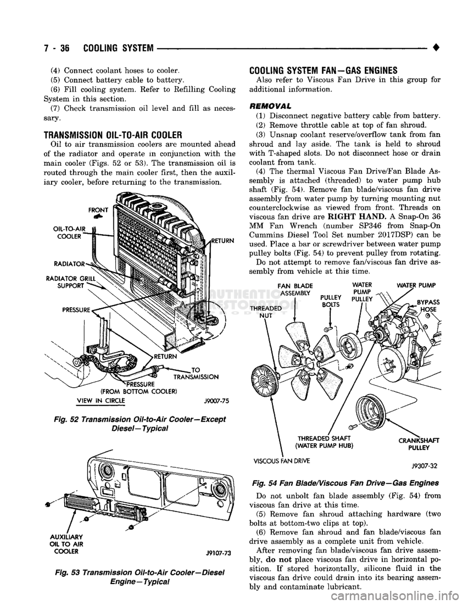
Oil to air transmission coolers are mounted ahead
of the radiator and operate in conjunction with the
main cooler (Figs, 52 or 53). The transmission oil is
routed through the main cooler first, then the auxil iary cooler, before returning to the transmission.
FRONT
OIL-TO-AIR
COOLER
RADIATOR
RADIATOR GRILL SUPPORT RETURN JO
_
TRANSMISSION
*
PRESSURE
(FROM BOTTOM COOLER)
VIEW
IN
CIRCLE J9007-75 Fig.
52
Transmission
Oil-to-Air Cooler—Except
Diesel—
Typical
AUXILIARY
OIL TO AIR
COOLER
J9107-73
Fig.
53
Transmission
Oil-to-Air
Cooler—Diesel
Engine—Typical
COOLING
SYSTEM FAN—GAS ENGINES
Also refer to Viscous Fan Drive in this group for
additional information.
REMOVAL (1) Disconnect negative battery cable from battery.
(2) Remove throttle cable at top of fan shroud.
(3) Unsnap coolant reserve/overflow tank from fan
shroud and lay aside. The tank is held to shroud
with T-shaped slots. Do not disconnect hose or drain
coolant from tank.
(4) The thermal Viscous Fan Drive/Fan Blade As
sembly is attached (threaded) to water pump hub
shaft (Fig. 54). Remove fan blade/viscous fan drive
assembly from water pump by turning mounting nut
counterclockwise as viewed from front. Threads on
viscous fan drive are RIGHT HAND. A Snap-On 36
MM Fan Wrench (number SP346 from Snap-On Cummins Diesel Tool Set number 2017DSP) can be
used. Place a bar or screwdriver between water pump
pulley bolts (Fig. 54) to prevent pulley from rotating. Do not attempt to remove fan/viscous fan drive as
sembly from vehicle at this time.
FAN BLADE
ASSEMBLY
THREADED NUT WATER
PUMP
PULLEY
PULLEY
BOLTS
WATER PUMP
THREADED SHAFT
(WATER PUMP HUB)
VISCOUS
FAN DRIVE CRANKSHAFT
PULLEY
J9307-32
Fig.
54 Fan
Blade/Viscous
Fan
Drive—Gas
Engines
Do not unbolt fan blade assembly (Fig. 54) from
viscous fan drive at this time.
(5) Remove fan shroud attaching hardware (two
bolts at bottom-two clips at top). (6) Remove fan shroud and fan blade/viscous fan
drive assembly as a complete unit from vehicle.
After removing fan blade/viscous fan drive assem
bly, do not place viscous fan drive in horizontal po sition. If stored horizontally, silicone fluid in the
viscous fan drive could drain into its bearing assem
bly and contaminate lubricant.
Page 308 of 1502
•
COOLING
SYSTEM
7 - 37
CAUTION:
Do not
remove
water
pump pulley-to-wa
ter
pump
bolts
(Fig. 54), This
pulley
is
under spring
tension.
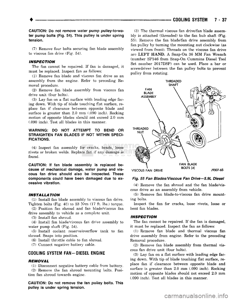
(7) Remove four bolts securing fan blade assembly
to viscous fan drive (Fig. 54).
INSPECTION The fan cannot be repaired. If fan is damaged, it
must be replaced. Inspect fan as follows:
(1) Remove fan blade and viscous fan drive as an
assembly from the engine. Refer to preceding Re
moval procedure.
(2) Remove fan blade assembly from viscous fan
drive unit (four bolts).
(3) Lay fan on a flat surface with leading edge fac
ing down. With tip of blade touching flat surface, re
place fan if clearance between opposite blade and surface is greater than 2.0 mm (.090 inch). Rocking
motion of opposite blades should not exceed 2.0 mm (.090 inch). Test all blades in this manner.
WARNING:
DO NOT
ATTEMPT
TO
BEND
OR
STRAIGHTEN
FAN
BLADES
IF NOT
WITHIN
SPECI
FICATIONS.
(4) Inspect fan assembly for cracks, bends, loose
rivets or broken welds. Replace fan if any damage is
found,
CAUTION:
If fan
blade assembly
is
replaced
be
cause
of
mechanical damage,
water
pump
and
vis
cous
fan
drive should
also
be
inspected. These
components
could have been damaged
due to ex
cessive
vibration.
INSTALLATION (1) Install fan blade assembly to viscous fan drive.
Tighten bolts (Fig. 48) to 23 N*m (17 ft. lbs.) torque. (2) Position fan shroud and fan blade/viscous fan
drive assembly to vehicle as a complete unit.
(3) Install fan shroud.
(4) Install fan blade/viscous fan drive assembly to
water pump shaft (Fig. 54). (5) Install coolant reserve/overflow tank to fan
shroud. Snaps into position.
(6) Install throttle cable to fan shroud.
(7) Connect negative battery cable.
COOLING
SYSTEM
FAN-DIESEL ENGINE
REMOVAL (1) Disconnect negative battery cable from battery.
(2) Remove the fan shroud mounting bolts. Posi
tion fan shroud towards engine.
CAUTION:
Do not
remove
the fan
puHey bolts. This pulley
is
under spring tension.
(3) The thermal viscous fan drive/fan blade assem
bly is attached (threaded) to the fan hub shaft (Fig.
55).
Remove the fan blade/fan drive assembly from
fan pulley by turning the mounting nut clockwise (as
viewed from front). Threads on the viscous fan drive are LEFT HAND. A Snap-On 36 MM Fan Wrench
(number SP346 from Snap-On Cummins Diesel Tool
Set number 2017DSP) can be used. Place a bar or
screwdriver between the fan pulley bolts to prevent
pulley from rotating.
THREADED
Fig.
55 Fan
Blades/Viscous
Fan Drive-5.9L
Diesel
(4) Remove the fan shroud and the fan blade/vis
cous drive as an assembly from vehicle.
(5) Remove fan blade-to-viscous fan drive mount
ing bolts.
Inspect the fan for cracks, loose rivets, loose or
bent fan blades.
INSPECTION The fan cannot be repaired. If the fan is damaged,
it must be replaced. Inspect the fan as follows:
(1) Remove fan blade and thermal viscous fan
drive assembly from engine. Refer to the preceding
Removal procedure.
(2) Remove fan blade assembly from thermal vis
cous fan drive unit (four bolts). (3) Lay fan on a flat surface with leading edge fac
ing down. With tip of blade touching flat surface, re
place fan if clearance between opposite blade and surface is greater than 2.0 mm (.090 inch). Rocking
motion of opposite blades should not exceed 2.0 mm (.090 inch). Test all blades in this manner.
Page 309 of 1502
7 - 38
COOLING
SYSTEM
•
WARNING:
DO NOT
ATTEMPT
TO
BEND
OR
STRAIGHTEN
FAN
BLADES
IF
NOT WITHIN
SPECI
FICATIONS.
(4) Inspect fan assembly for cracks, bends, loose
rivets or broken welds. Replace fan if any damage is
found.
CAUTION; If the fan
blade assembly
is
replaced
be
cause
of
mechanical damage,
the fan
pulley
and
viscous
fan
drive should also
be
inspected.
These
components
could have been damaged
due to ex
cessive
vibration.
INSTALLATION
(1) Install fan blade assembly to viscous fan drive.
Tighten mounting bolts.
(2) Position the fan shroud and fan blade/viscous
fan drive to the vehicle as an assembly.
(3) Install viscous fan drive assembly on fan hub
shaft. Tighten mounting nut to 57 N*m (42 ft. lbs.)
torque.
(4) Install fan shroud bolts.
(5) Install battery cable to battery.
VISCOUS
FAN
DRIVE
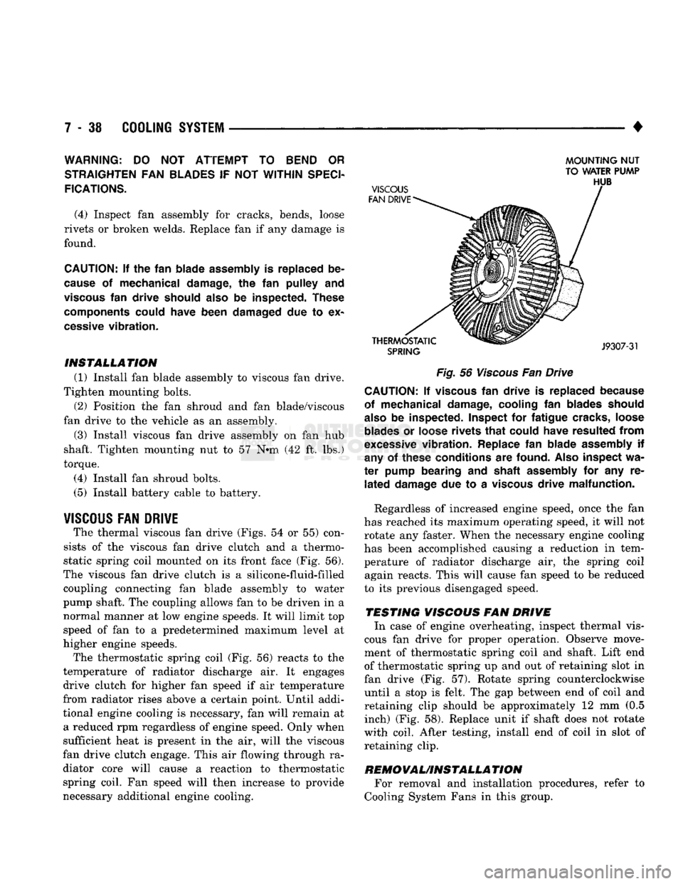
The thermal viscous fan drive (Figs. 54 or 55) con
sists of the viscous fan drive clutch and a thermo
static spring coil mounted on its front face (Fig. 56).
The viscous fan drive clutch is a silicone-fluid-filled coupling connecting fan blade assembly to water
pump shaft. The coupling allows fan to be driven in a normal manner at low engine speeds. It will limit top
speed of fan to a predetermined maximum level at
higher engine speeds.
The thermostatic spring coil (Fig. 56) reacts to the
temperature of radiator discharge air. It engages drive clutch for higher fan speed if air temperature
from radiator rises above a certain point. Until addi
tional engine cooling is necessary, fan will remain at a reduced rpm regardless of engine speed. Only when
sufficient heat is present in the air, will the viscous
fan drive clutch engage. This air flowing through ra diator core will cause a reaction to thermostatic spring coil. Fan speed will then increase to provide
necessary additional engine cooling.
MOUNTING
NUT
TO WATER PUMP
Fig.
56
Viscous
Fan Drive CAUTION; If
viscous
fan
drive
is
replaced because
of mechanical damage, cooling
fan
blades should
also
be
inspected. Inspect
for
fatigue cracks, loose
blades
or
loose rivets
that
could have resulted
from
excessive
vibration. Replace
fan
blade assembly
if
any
of
these conditions
are
found.
Also
inspect
wa
ter
pump bearing
and
shaft assembly
for any re
lated
damage
due to a
viscous
drive malfunction.
Regardless of increased engine speed, once the fan
has reached its maximum operating speed, it will not
rotate any faster. When the necessary engine cooling
has been accomplished causing a reduction in tem perature of radiator discharge air, the spring coil again reacts. This will cause fan speed to be reduced
to its previous disengaged speed.
TESTING VISCOUS FAN DRIVE In case of engine overheating, inspect thermal vis
cous fan drive for proper operation. Observe move
ment of thermostatic spring coil and shaft. Lift end
of thermostatic spring up and out of retaining slot in
fan drive (Fig. 57). Rotate spring counterclockwise until a stop is felt. The gap between end of coil and
retaining clip should be approximately 12 mm (0.5 inch) (Fig. 58). Replace unit if shaft does not rotate
with coil. After testing, install end of coil in slot of retaining clip.
REMOVAUINSTALLA
TION For removal and installation procedures, refer to
Cooling System Fans in this group.