1993 DODGE TRUCK battery
[x] Cancel search: batteryPage 39 of 1502
0
- 21
LUBRICATION
AND
MAINTENANCE
• SERVICE INFORMATION
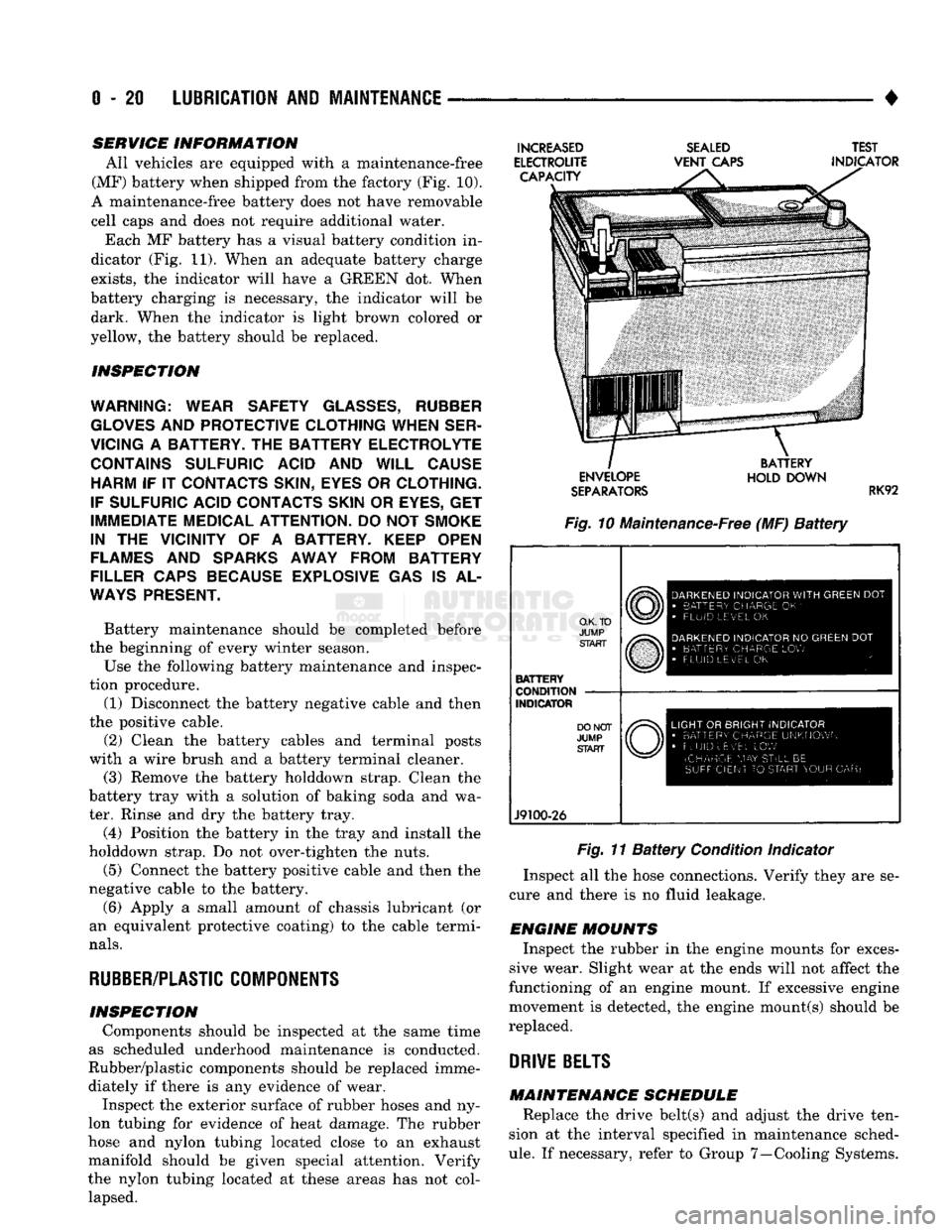
All vehicles are equipped with a maintenance-free
(MF) battery when shipped from the factory (Fig. 10).
A maintenance-free battery does not have removable
cell caps and does not require additional water. Each MF battery has a visual battery condition in
dicator (Fig. 11). When an adequate battery charge
exists,
the indicator will have a GREEN dot. When
battery charging is necessary, the indicator will be dark. When the indicator is light brown colored or
yellow, the battery should be replaced.
INSPECTION
WARNING; WEAR SAFETY
GLASSES,
RUBBER
GLOVES
AND
PROTECTIVE CLOTHING WHEN SER
VICING
A
BATTERY.
THE
BATTERY ELECTROLYTE CONTAINS SULFURIC ACID
AND
WILL CAUSE HARM
IF IT
CONTACTS SKIN, EYES
OR
CLOTHING.
IF SULFURIC ACID CONTACTS SKIN
OR
EYES,
GET
IMMEDIATE MEDICAL ATTENTION.
DO
NOT
SMOKE
IN
THE
VICINITY
OF A
BATTERY. KEEP OPEN
FLAMES
AND
SPARKS AWAY FROM BATTERY
FILLER CAPS BECAUSE EXPLOSIVE
GAS IS AL
WAYS
PRESENT.
Battery maintenance should be completed before
the beginning of every winter season.
Use the following battery maintenance and inspec
tion procedure. (1) Disconnect the battery negative cable and then
the positive cable.
(2) Clean the battery cables and terminal posts
with a wire brush and a battery terminal cleaner. (3) Remove the battery holddown strap. Clean the
battery tray with a solution of baking soda and wa
ter. Rinse and dry the battery tray.
(4) Position the battery in the tray and install the
holddown strap. Do not over-tighten the nuts.
(5) Connect the battery positive cable and then the
negative cable to the battery.
(6) Apply a small amount of chassis lubricant (or
an equivalent protective coating) to the cable termi
nals.
RUBBER/PLASTIC
COMPONENTS
INSPECTION Components should be inspected at the same time
as scheduled underhood maintenance is conducted.
Rubber/plastic components should be replaced imme diately if there is any evidence of wear. Inspect the exterior surface of rubber hoses and ny
lon tubing for evidence of heat damage. The rubber
hose and nylon tubing located close to an exhaust
manifold should be given special attention. Verify
the nylon tubing located at these areas has not col lapsed.
INCREASED
ELECTROUTE CAPACITY
SEALED
VENT
CAPS TEST
INDICATOR ENVELOPE
SEPARATORS
BATTERY
HOLD DOWN
RK92
Fig. 10 Maintenance-Free (MF)
Battery
O.K. TO
JUMP START
BATTERY
CONDITION
INDICATOR
J9100-26
DARKENED
INDICATOR
WITH
GREEN
DOT
•
BATTERY CHARGE
OK '
•
FLUID LEVEL
OK
DARKENED
INDICATOR
NO
GREEN
DOT
•
BATTERY CHARGE
LOW
FLUID LEVEL
OK
LIGHT
OR
BRIGHT INDICATOR
•
BATTERY CHARGE UNKNOWN
•
FLUID uEv'EL
LOW
(CHARGE
MAY
STILL
BE
SUFFICIENT
TO
START YOUR
CAR)
Fig. 11
Battery
Condition Indicator
Inspect all the hose connections. Verify they are se
cure and there is no fluid leakage.
ENGINE MOUNTS Inspect the rubber in the engine mounts for exces
sive wear. Slight wear at the ends will not affect the
functioning of an engine mount. If excessive engine
movement is detected, the engine mount(s) should be
replaced.
DRIVE
BELTS
MAINTENANCE SCHEDULE Replace the drive belt(s) and adjust the drive ten
sion at the interval specified in maintenance sched
ule.
If necessary, refer to Group 7—Cooling Systems.
Page 210 of 1502
•
BRAKES
5 - 23
VACUUM PUMP OPERATION
Vacuum pump output is transmitted to the power
brake booster through a supply hose. The hose is con nected to an outlet port on the pump housing and to
the check valve in the power brake booster.
Pump output ranges from a minimum of 8.5 to 25
inches vacuum. The pump rotor and vanes are rotated by the pump
drive gear. The drive gear is operated by the cam
shaft gear. Booster vacuum level is monitored by a warning
switch (Fig. 2). The switch consists of a vacuum
chamber that measures vacuum level and a sensor in
circuit with the brake warning light. The vacuum chamber is connected to the booster
check valve by a vacuum supply hose. A wire har
ness connects the switch sensor to the brake warning
light. If booster vacuum falls below 8.5 inches for 8-10 seconds or more, the switch sensor completes
the circuit to the warning light causing it to illumi
nate.
VACUUM PUMP DIAGNOSIS
Vacuum pump diagnosis involves checking pump
output with a vacuum gauge. The low vacuum warn
ing switch can also be checked with a vacuum gauge.
Refer to the diagnosis procedure in this section. A standard vacuum gauge can be used to check
pump output when necessary. Simply disconnect the
pump supply hose and connect a vacuum gauge to
the outlet port for testing purposes. Vacuum should
hold steady in a range of approximately 8.5 to 25 inches at various engine speeds.
DIAGNOSING LOW VACUUM OUTPUT CONDITION A low booster vacuum condition or a faulty low
vacuum warning switch will cause the brake warn ing light to illuminate. If the light does go on and in
dicates the existence of a low vacuum condition,
check the vacuum pump, booster and warning switch
as follows:
(1) Check vacuum pump oil feed line. Verify that
line connections are secure and not leaking. If leak age is noted and pump is noisy, replace pump.
(2) Disconnect supply hose to booster. Connect vac
uum gauge to this hose and run engine at various
throttle openings. Output should range from 8.5 to 25 inches vacuum. If vacuum is consistently below
8.5 inches, problem is with vacuum hoses or pump
component. If output is within specified limits, con
tinue testing.
(3) Check booster operation as described in diagno
sis section. Replace check valve, vacuum hoses, or
booster if necessary. However, if booster operation is correct but warning light is still on, continue testing. (4) Disconnect vacuum hose at warning switch.
Plug hose and connect hand vacuum pump to switch. (5) Start and run engine.
(6) Apply 8.5 to 9 inches of vacuum to warning
switch and observe warning light. If light goes out,
switch vacuum hose is either loose or leaking. If
light remains on, leave engine running and continue
testing.
(7) Apply 20-25 inches vacuum to switch and ob
serve warning light operation. If light now goes out,
switch is at fault and should be replaced. If light re
mains on, continue testing.
(8) Reconnect vacuum hoses and replace original
warning switch with known good switch. Run engine and observe warning light operation. If light is now
off, old switch is faulty. If light remains on, problem
is in wiring between switch and warning light.
VACUUM-STEERING PUMP
ASSEMBLY
REMOVAL
(1) Disconnect battery negative cable.
(2) Position drain pan under power steering pump.
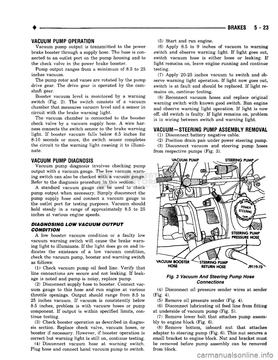
(3) Disconnect vacuum and steering pump hoses
from respective pumps (Fig. 3).
Fig.
3
Vacuum
And Steering
Pump Hose
Connections
(4) Disconnect oil pressure sender wires at sender
(Fig. 4).
(5) Remove oil pressure sender (Fig. 4).
(6) Disconnect lubricating oil feed line from fitting
at underside of vacuum pump (Fig. 5).
(7) Remove lower bolt that attaches pump assem
bly to engine block (Fig. 6).
(8) Remove bottom, inboard nut that attaches
adapter to steering pump (Fig. 6). This nut secures a
small bracket to engine block. Nut and bracket must
be removed before pump assembly can be removed from block.
Page 213 of 1502
5
- 26
BRAKES
Fig. 13 Positioning Gasket On Pump Mounting
Flange
(2) Insert pump assembly upper attaching bolt in
mounting flange and gasket. Use sealer or grease to
hold bolt in place if necessary.
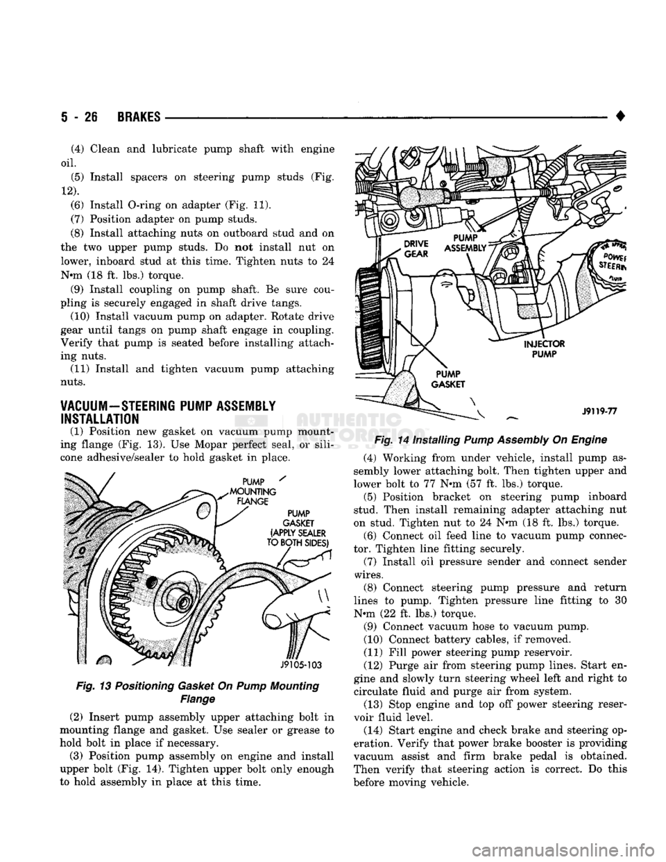
(3) Position pump assembly on engine and install
upper bolt (Fig. 14). Tighten upper bolt only enough
to hold assembly in place at this time. •
Fig. 14 Installing Pump Assembly On Engine (4) Working from under vehicle, install pump as
sembly lower attaching bolt. Then tighten upper and
lower bolt to 77 N»m (57 ft. lbs.) torque. (5) Position bracket on steering pump inboard
stud. Then install remaining adapter attaching nut
on stud. Tighten nut to 24 N«m (18 ft. lbs.) torque.
(6) Connect oil feed line to vacuum pump connec
tor. Tighten line fitting securely.
(7) Install oil pressure sender and connect sender
wires.
(8) Connect steering pump pressure and return
lines to pump. Tighten pressure line fitting to 30
N-m (22 ft. lbs.) torque.
(9) Connect vacuum hose to vacuum pump.
(10) Connect battery cables, if removed.
(11) Fill power steering pump reservoir.
(12) Purge air from steering pump lines. Start en
gine and slowly turn steering wheel left and right to circulate fluid and purge air from system.
(13) Stop engine and top off power steering reser
voir fluid level.
(14) Start engine and check brake and steering op
eration. Verify that power brake booster is providing
vacuum assist and firm brake pedal is obtained.
Then verify that steering action is correct. Do this
before moving vehicle.
(4) Clean and lubricate pump shaft with engine
oil.
(5) Install spacers on steering pump studs (Fig.
12).
(6) Install O-ring on adapter (Fig. 11).
(7) Position adapter on pump studs.
(8) Install attaching nuts on outboard stud and on
the two upper pump studs. Do not install nut on
lower, inboard stud at this time. Tighten nuts to 24
N-m (18 ft. lbs.) torque. (9) Install coupling on pump shaft. Be sure cou
pling is securely engaged in shaft drive tangs. (10) Install vacuum pump on adapter. Rotate drive
gear until tangs on pump shaft engage in coupling.
Verify that pump is seated before installing attach
ing nuts. (11) Install and tighten vacuum pump attaching
nuts.
VACUUM-STEERING PUMP ASSEMBLY INSTALLATION
(1) Position new gasket on vacuum pump mount
ing flange (Fig. 13). Use Mopar perfect seal, or sili
cone adhesive/sealer to hold gasket in place.
Page 250 of 1502
•
BRAKES
5 - 63 You must count the long flash along with the
short flashes for an accurate fault code count.
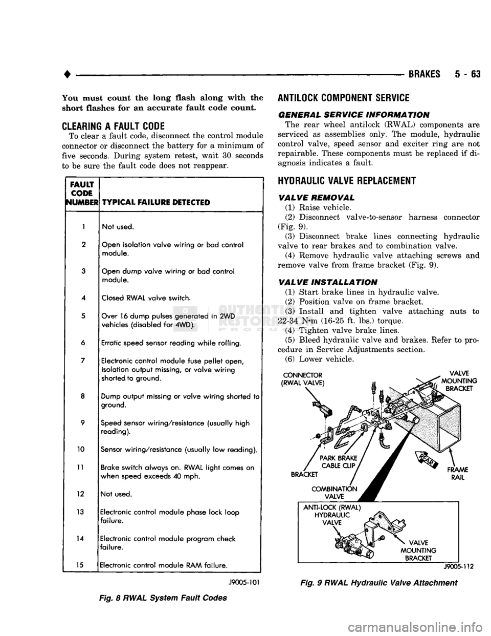
CLEARING
A
FAULT CODE
To clear a fault code, disconnect the control module
connector or disconnect the battery for a minimum of
five seconds. During system retest, wait 30 seconds
to be sure the fault code does not reappear.
FAULT
CODE
NUMBER
TYPICAL
FAILURE
DETECTED
1
Not used.
2
Open
isolation valve wiring
or
bad control
module.
3
Open
dump valve wiring
or
bad control
module.
4
Closed
RWAL
valve switch.
5
Over 16 dump pulses generated
in
2WD
vehicles (disabled
for
4WD).
6 Erratic speed sensor reading while rolling.
7 Electronic control module fuse
pellet
open,
isolation output
missing,
or
valve wiring
shorted to ground.
8
Dump
output
missing
or
valve wiring shorted
to
ground.
9
Speed
sensor wiring/resistance (usually high
reading).
10
Sensor
wiring/resistance (usually
low
reading).
11
Brake switch always on.
RWAL
light comes
on
when speed exceeds
40
mph.
12 Not used.
13 Electronic control module phase lock loop
failure.
14 Electronic control module program check
failure.
15 Electronic control module
RAM
failure.
J9005-101
Fig.
8
RWAL
System
Fault
Codes ANTILOCK COMPONENT SERVICE
GENERAL SERVICE INFORMATION
The rear wheel antilock (RWAL) components are
serviced as assemblies only. The module, hydraulic
control valve, speed sensor and exciter ring are not
repairable. These components must be replaced if di agnosis indicates a fault.
HYDRAULIC VALVE REPLACEMENT VALVE REMOVAL
(1) Raise vehicle.
(2)
Disconnect valve-to-sensor harness connector
(Fig. 9). (3) Disconnect brake lines connecting hydraulic
valve to rear brakes and to combination valve.
(4) Remove hydraulic valve attaching screws and
remove valve from frame bracket (Fig. 9).
VALVE INSTALLATION
(1) Start brake lines in hydraulic valve.
(2)
Position valve on frame bracket. (3) Install and tighten valve attaching nuts to
22-34 N-m (16-25 ft. lbs.) torque. (4) Tighten valve brake lines.
(5)
Bleed hydraulic valve and brakes. Refer to pro
cedure in Service Adjustments section.
(6)
Lower vehicle.
J9005-112
Fig.
9
RWAL
Hydraulic
Valve
Attachment
Page 286 of 1502
•
COOLING SYSTEM
7 - 15
SERVICE
PROCEDURES
INDEX
page
Coolant
26
Coolant Reserve/Overflow System
30
Cooling System Cleaning/Reverse Flushing
28
Cooling System Fan—Diesel Engine
. 37
Cooling System
Fan—Gas
Engines
36
Cooling System
Hoses
34
Draining Cooling System
27
Pressure
Testing
Radiator
Caps
............. 32
Radiator Pressure
Cap 31
Radiators
32
Refilling
the
Cooling System
28
WATER PUMPS—EXCEPT DIESEL
A centrifugal water pump circulates coolant
through the water jackets, passages, intake manifold,
radiator core, cooling system hoses and heater core.
The pump is driven from the engine crankshaft by a drive belt. The water pump impeller is pressed onto the rear
of a shaft that rotates in a bearing pressed into the
water pump body. The body has a small hole for ven
tilation. The water pump seals are lubricated by an
tifreeze in the coolant mixture. Additional lubrication is not necessary. A quick test to determine if pump is working is to
check if heater warms properly. A defective water
pump will not be able to circulate heated coolant
through the long heater hose to the heater core. The water pump on all models can be removed
without discharging the air conditioning system (if equipped).
REMOVAL The water pump on all gas powered engines is
bolted directly to the engine timing chain case/cover.
A gasket is used as a seal between the water pump
and timing chain case/cover.
If water pump is replaced because of bearing/shaft
damage or leaking shaft seal, the mechanical cooling
fan assembly should also be inspected. Inspect for fa tigue cracks, loose blades or loose rivets that could
have resulted from excessive vibration. Replace fan if any of these conditions are found. Also check condi
tion of the thermal viscous fan drive. Refer to Vis
cous Fan Drive in this group. (1) Disconnect negative battery cable from battery.
(2) Drain cooling system. Refer to Draining Cool
ing System in this group. Do not waste reusable coolant. If solution is clean,
drain coolant into a clean container for reuse.
(3)
Disconnect throttle cable from clip at top of fan
shroud.
page
Testing
Cooling System
for
Leaks
. 29
Thermostat
22
Transmission
Oil
Cooler—Diesel
35
Transmission
Oil
Cooler—Except Diesel
35
Transmission Oil-To-Air Cooler
36
Viscous
Fan
Drive
38
Water
Pump
Bypass
Hose—All
Gas
Powered
Engines
.............................. 19
Water
Pumps—5.9L Diesel
18
Water
Pumps—Except Diesel
15
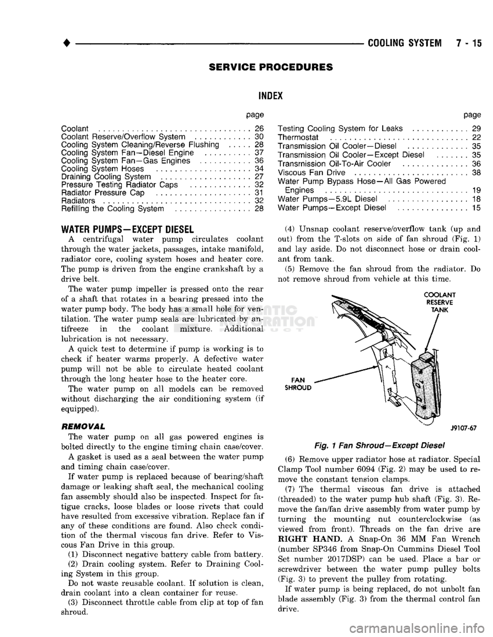
(4) Unsnap coolant reserve/overflow tank (up and
out) from the T-slots on side of fan shroud (Fig. 1) and lay aside. Do not disconnect hose or drain cool
ant from tank.
(5) Remove the fan shroud from the radiator. Do
not remove shroud from vehicle at this time.
FAN
SHROUD
J9107-67
Fig.
1 Fan
Shroud—Except
Diesel
(6) Remove upper radiator hose at radiator. Special
Clamp Tool number 6094 (Fig. 2) may be used to re
move the constant tension clamps.
(7) The thermal viscous fan drive is attached
(threaded) to the water pump hub shaft (Fig. 3). Re
move the fan/fan drive assembly from water pump by
turning the mounting nut counterclockwise (as viewed from front). Threads on the fan drive are RIGHT HAND. A Snap-On 36 MM Fan Wrench (number SP346 from Snap-On Cummins Diesel Tool
Set number 2017DSP) can be used. Place a bar or
screwdriver between the water pump pulley bolts (Fig. 3) to prevent the pulley from rotating.
If water pump is being replaced, do not unbolt fan
blade assembly (Fig. 3) from the thermal control fan drive.
Page 289 of 1502
7 - 18
COOLING
SYSTEM
• (9) Relax tension from automatic belt tensioner
(Figs.
4 or 5). Install drive belt.
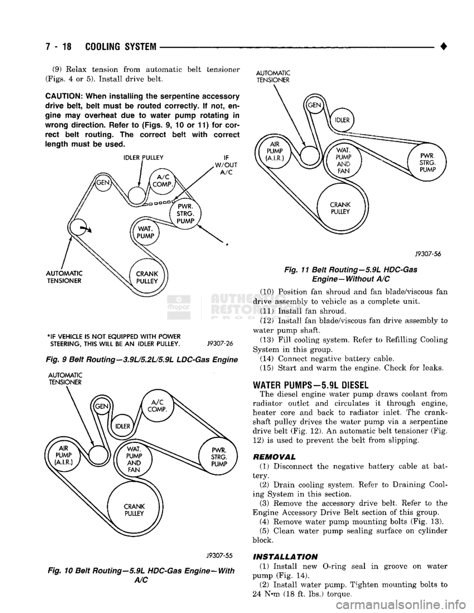
CAUTION:
When
installing
the
serpentine
accessory
drive
belt, belt
must
be
routed
correctly.
If not, en
gine
may
overheat
due to
water
pump
rotating
in
wrong
direction.
Refer
to
(Figs,
i, 10 or 11) for
cor
rect
belt
routing.
The
correct
belt with
correct
length
must
be
used.
*IF
VEHICLE
IS NOT
EQUIPPED
WITH
POWER
STEERING,
THIS
WILL
BE
AN
IDLER
PULLEY.
J9307-26
Fig.
9 Belt Routing—3.9U5.2L/5.9L
LDC-Gas
Engine
AUTOMATIC
TENSIONER
AUTOMATIC
TENSIONER
J9307-56
Fig.
11 Belt Routing—5.9L
HDC-Gas
Engine—Without
A/C (10) Position fan shroud and fan blade/viscous fan
drive assembly to vehicle as a complete unit. (11) Install fan shroud.
(12) Install fan blade/viscous fan drive assembly to
water pump shaft.
(13) Fill cooling system. Refer to Refilling Cooling
System in this group. (14) Connect negative battery cable.
(15) Start and warm the engine. Check for leaks.
WATER
PUMPS—5.9L
DIESEL
The diesel engine water pump draws coolant from
radiator outlet and circulates it through engine,
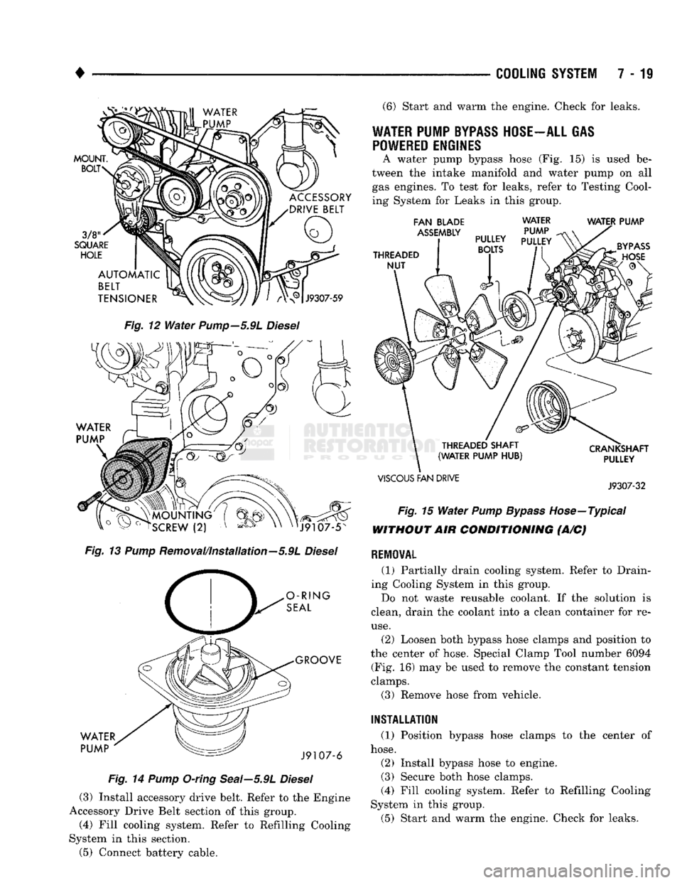
heater core and back to radiator inlet. The crank shaft pulley drives the water pump via a serpentine
drive belt (Fig. 12). An automatic belt tensioner (Fig. 12) is used to prevent the belt from slipping.
REMOVAL (1) Disconnect the negative battery cable at bat
tery. (2) Drain cooling system. Refer to Draining Cool
ing System in this section.
(3) Remove the accessory drive belt. Refer to the
Engine Accessory Drive Belt section of this group. (4) Remove water pump mounting bolts (Fig. 13).
(5) Clean water pump sealing surface on cylinder
block.
J9307-55
Fig.
10 Belt Routing—5.9L
HDC-Gas
Engine-With
A/C
INSTALLATION
(1) Install new O-ring seal in groove on water
pump (Fig. 14). (2) Install water pump. Tighten mounting bolts to
24 N-m (18 ft. lbs.) torque.
Page 290 of 1502
•
COOLING
SYSTEM
7-11
MOUNT.
BOLT
3/8
SQUARE
HOLE
ACCESSORY
DRIVE
BELT AUTOMATIC
BELT
TENSIONER
J9307-59
Fig.
12
Water
Pump—5.91
Diesel
o ~ " o
rSCREW
(2) v '^ov XN
nJ9107-5N
Fig.
13
Pump
Removal/Installation—5.9L
Diesel
O-RING
SEAL
WATER
PUMP
GROOVE
J9107-6
Fig.
14
Pump
O-ring Seal—5.9L
Diesel
(3) Install accessory drive belt. Refer to the Engine
Accessory Drive Belt section of this group.
(4) Fill cooling system. Refer to Refilling Cooling
System in this section.
(5) Connect battery cable. (6) Start and warm the engine. Check for leaks.
WATER PUMP
BYPASS
HOSE-ALL GAS POWERED ENGINES
A water pump bypass hose (Fig. 15) is used be
tween the intake manifold and water pump on all gas engines. To test for leaks, refer to Testing Cool
ing System for Leaks in this group.
FAN
BLADE
ASSEMBLY
THREADED
NUT
WATER
PUMP
PULLEY
PULLEY BOLTS WATER PUMP
THREADED SHAFT
(WATER PUMP
HUB)
VISCOUS
FAN DRIVE CRANKSHAFT
PULLEY
J9307-32
Fig.
15
Water
Pump Bypass
Hose—Typical
WITHOUT AIR CONDITIONING (A/C)
RE10WAL
(1) Partially drain cooling system. Refer to Drain
ing Cooling System in this group.
Do not waste reusable coolant. If the solution is
clean, drain the coolant into a clean container for re
use.
(2) Loosen both bypass hose clamps and position to
the center of hose. Special Clamp Tool number 6094 (Fig. 16) may be used to remove the constant tension
clamps.
(3) Remove hose from vehicle.
INSTALLATION
(1) Position bypass hose clamps to the center of
hose.
(2) Install bypass hose to engine.
(3) Secure both hose clamps.
(4) Fill cooling system. Refer to Refilling Cooling
System in this group.
(5) Start and warm the engine. Check for leaks.
Page 291 of 1502

7 - 20
COOLING
SYSTEM
•
HOSE
CLAMP
HOSE
J9207-36
Fig.
16
Hose
Clamp
Tool
WITH AIR
CONDITIONING
(A/C)
REMOVAL
If equipped with A/C, the generator and A/C com
pressor along with their common mounting bracket (Fig. 17) must be partially removed. Removing the
generator or A/C compressor from their mounting
bracket is not necessary. Also, discharging the A/C system is not necessary. Do not remove any refrig
erant lines from A/C compressor.
SUPPORT BRACKET (ROD)
GENERATOR/COMPRESSOR
MOUNTING
BRACKET
J9307-66
Fig.
17 Generator—A/C
Compressor
Mounting
Bracket—
Typical
WARNING;
THE A/C
SYSTEM
IS
UNDER
PRESSURE
EVEN
WITH
THE
ENGINE OFF. REFER
TO
REFRIG
ERANT
WARNINGS
IN
GROUP
24,
HEATING
AND
AIR
CONDITIONING.
(1) Disconnect negative battery cable from battery. (2) Partially drain cooling system. Refer to Drain
ing Cooling System in this group.
Do not waste reusable coolant. If the solution is
clean, drain the coolant into a clean container for re
use.
(3) Remove upper radiator hose clamp at radiator.
Special Clamp Tool number 6094 (Fig. 16) may be
used to remove the constant tension clamps. Remove
hose at radiator.
(4) Disconnect throttle cable from clip at radiator
fan shroud. (5) Unplug wiring harness from A/C compressor.
(6) Remove the air cleaner assembly.
(7) Remove accessory drive belt. Refer to Belt Re
moval/Installation in the Engine Accessory Drive
Belt section of this group.
(8) 3.9L/5.2L/5.9L LDC-Gas: The drive belt idler
pulley must be removed to gain access to one of the
A/C compressor/generator bracket mounting bolts. Remove the idler pulley bolt and remove idler pulley (Fig. 18).
GENERATOR/COMPRESSOR
AND
BRACKET
SUPPORT BRACKET
IGNITION
COIL
BRACKET
Fig.
18 Idler Pulley-3.9U5.2U5.9L
LDC-Gas
Engine
5.9L HDC-Gas: The automatic belt tensioner/pul-
ley assembly must be removed to gain access to one
of the A/C compressor/generator bracket mounting
bolts.
Remove the tensioner mounting bolt (Fig. 19) and remove tensioner.
(9) Remove the engine oil dipstick tube mounting
bolt at the side of the A/C-generator mounting
bracket.
(10) Disconnect throttle body control cables. Refer
to Accelerator Pedal and Throttle Cable in Group 14,
Fuel System.