1993 DODGE TRUCK battery
[x] Cancel search: batteryPage 1471 of 1502
24
- 34
HEATING
AND
AIR
CONDITIONING
• (10) Remove unit retaining nuts
on
engine side
(6
nuts).
(11) Remove unit.
(12) Remove screws
and
mode door crank
to
sepa
rate cover from housing. (13) Carefully slide heater core
out.
(14) Peel dash panel seal below cover. Remove
re
taining screws
and
remove cover from blower motor assembly.
(15) Separate
fan
from motor, motor from housing
and inspect
all
parts.
INSTALLATION (1) Assemble heater assembly using necessary
new
parts.
(2) Position heater assembly
to
dash
and
install
re
taining nuts
on
engine side.
(3) Install cowl side retaining screws.
(4) Connect blower motor.
(5) Connect control cables.
(6) Install right, lower instrument panel reinforce
ment.
(7) Install structural brace through glove
box
open
ing.
(8) Install glove
box.
(9) Install right cowl side trim panel,
if
equipped. (10) Unplug inlets
and
water hoses
and
connect
hoses
to
inlets
on
package
(Fig. 8).
(11) Connect
the
negative cable
to the
battery.
DEFROSTER
DUCT
REMOVAL
(1) Disconnect
the
negative cable from
the
battery.
(2) Open glove
box
past stops.
(3)
If
equipped, remove right upper
air
duct
by re
moving mounting screw
and
pulling duct
out
through
glove
box
openings
(Fig. 9).
(4) Remove instrument panel center brace.
(5) Remove right kick
pad.
(6) Remove right instrument panel pivot bolt.
(7) Remove instrument panel cluster.
(8) Disconnect shift lever cable,
if
equipped.
(9) Lower steering column.
(10) Remove steering column studs. (11) Remove radio,
if
equipped.
(12) Remove mounting screws
and
remove scoop
connecting heater unit
to
center distribution duct,
if
equipped.
(13) Remove mounting screws
and
remove center
distribution duct
by
pulling bottom
of
instrument
panel
out and
dropping duct
out (Fig. 9).
(14) Remove heater control.
(15) Remove mounting screws
and the
cover that
retains instrument panel wiring.
Let
wiring hang
free.
(16) Remove mounting screw
and
slide left
air
duct
out through instrument cluster opening,
if
equipped
(Fig.
9).
(17) Remove screws attaching defroster duct
to
dash panel
(Fig. 9).
(18) Reach
in
through instrument panel opening
and disengage snaps
to
separate defroster duct into
2
pieces.
(19) Remove defroster duct halves through instru
ment cluster opening.
INSTALLATION (1) Install defroster duct halves through instru
ment cluster opening. (2) Reach
in
through instrument panel opening
and engage snaps
to
connect defroster duct halves.
(3) Install screws attaching defroster duct
to
dash
panel
(Fig. 9).
(4) Slide left
air
duct
out
through instrument clus
ter opening,
if
equipped
(Fig. 9).
Install mounting screw.
(5) Position
the
cover that retains instrument
panel wiring. Install mounting screws.
(6) Install
the
heater control.
(7) Position
the
center distribution duct
in
bottom
of instrument panel
out, if
equipped
(Fig. 9).
Install
mounting screws. (8) Position
the
scoop connecting heater unit
to
center distribution duct,
if
equipped. Install mount ing screws.
(9) Install
the
radio,
if
equipped.
(10) Install steering column studs.
(11) Position
the
steering column
in
place. (12) Connect shift lever cable,
if
equipped.
(13) Install instrument panel cluster.
(14) Install right instrument panel pivot bolt.
(15) Install right kick
pad.
(16) Install instrument panel center brace.
(17) Position
the
right upper
air
duct
in
through
glove
box
openings,
if
equipped
(Fig. 9).
Install
mounting screw.
(18) Close glove
box.
(19) Connect
the
negative cable
to the
battery.
EVAPORATOR CONTROL UNIT
REMOVAL (1) Remove faceplate.
(2) Remove attaching screws.
(3) Pull control unit
out,
away from instrument
panel. (4) Disconnect blower control switch wiring con
nector. (5) Disconnect
3
wiring connectors
to
evaporator
control unit. (6) Disconnect illumination light.
(7) Disconnect vacuum harness.
(8) Disconnect temperature control cable.
Page 1473 of 1502
24 - 36
HEATING
AND AIR
CONDITIONING
• (9) Remove control.
INSTALLATION
(1) Connect temperature control cable.
(2) Install illumination light.
(3) Install 3 wiring connectors to push button
switch and vacuum harness. (4) Connect blower motor control switch wiring
connector.
(5) Place control unit in place in instrument panel
and secure with attaching screws.
(6) Install faceplate.
VACUUM ACTUATORS
The mode and air circulator actuators are serviced
through the glove box opening after opening the glove box past its stops. The heater/defroster actuator is serviced under the
instrument panel on the left end of the A/C unit.
EVAPORATOR HEATER ASSEMBLY
REMOVAL
(1) Disconnect the negative cable from the battery.
(2) Discharge refrigerant from the A/C system.
(3) Disconnect refrigerant and heater lines from
unit on engine side.
(4) Plug heater hoses and unit and remove conden
sate tube (Fig. 9).
(5) Move transfer case and/or gear shift levers
away from instrument panel.
(6) Remove right cowl side trim panel, if so
equipped.
(7) Remove glove box by removing mounting
screws at base and swinging out from the bottom to
avoid catch and stops.
(8) Remove structural brace through glove box
opening. Remove screws, loosen nuts.
(9) Remove ash receiver.
(10) Remove right half of lower reinforcement by
removing screws attaching it to the instrument panel and the sctew attaching it to the cowl side trim
panel.
(11) Detach radio ground strap.
(12) Remove center distribution duct.
(13) Remove floor air distribution duct.
(14) Disconnect temperature control cable from
unit through glove box and tape out of way. (15) Disconnect vacuum lines from extension on
control unit and detach vacuum lines from defroster
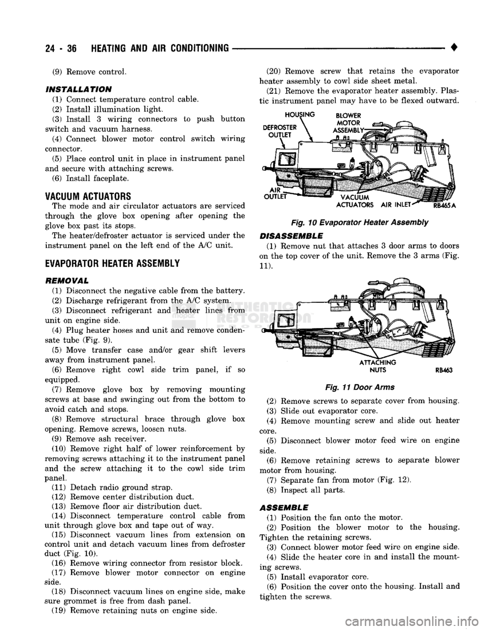
duct (Fig. 10). (16) Remove wiring connector from resistor block.
(17) Remove blower motor connector on engine
side.
(20) Remove screw that retains the evaporator
heater assembly to cowl side sheet metal.
(21) Remove the evaporator heater assembly. Plas
tic instrument panel may have to be flexed outward.
Fig.
10 Evaporator Heater
Assembly
DISASSEMBLE
(1) Remove nut that attaches 3 door arms to doors
on the top cover of the unit. Remove the 3 arms (Fig.
11).
ATTACHING
NUTS
RB463
Fig.
11
Door Arms
(2) Remove screws to separate cover from housing.
(3) Slide out evaporator core. (4) Remove mounting screw and slide out heater
core.
(5) Disconnect blower motor feed wire on engine
side.
(6) Remove retaining screws to separate blower
motor from housing.
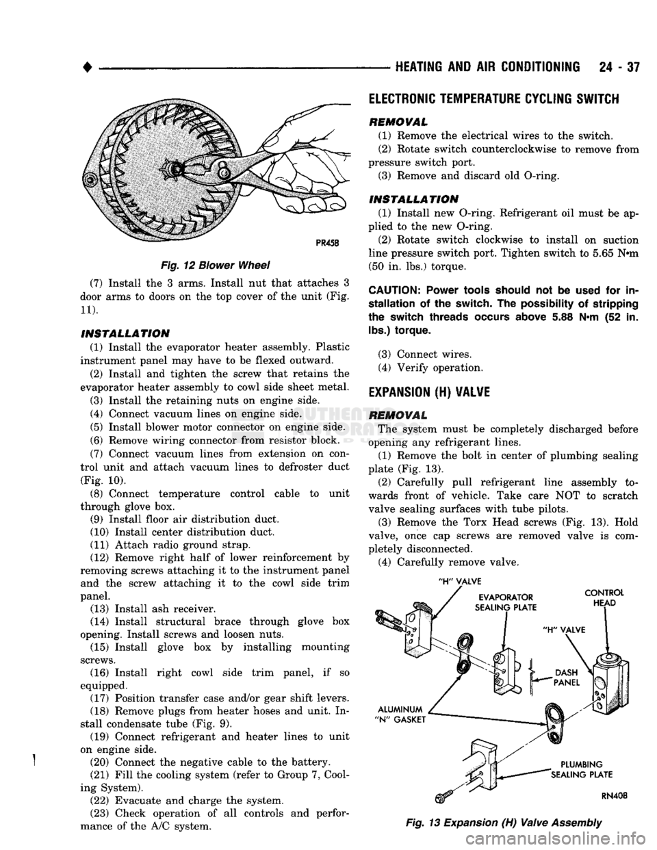
(7) Separate fan from motor (Fig. 12).
(8) Inspect all parts.
ASSEMBLE
(1) Position the fan onto the motor.
(2) Position the blower motor to the housing.
Tighten the retaining screws. (3) Connect blower motor feed wire on engine side.
(4) Slide the heater core in and install the mount
ing screws.
(5) Install evaporator core.
(6) Position the cover onto the housing. Install and
tighten the screws. (18) Disconnect vacuum lines on engine side, make
sure grommet is free from dash panel. (19) Remove retaining nuts on engine side.
Page 1474 of 1502
•
Fig.
12
Blower
Wheel
(7) Install the 3 arms. Install nut that attaches 3
door arms to doors on the top cover of the unit (Fig.
11).
INSTALLATION
(1) Install the evaporator heater assembly. Plastic
instrument panel may have to be flexed outward.
(2) Install and tighten the screw that retains the
evaporator heater assembly to cowl side sheet metal.
(3) Install the retaining nuts on engine side.
(4) Connect vacuum lines on engine side.
(5) Install blower motor connector on engine side.
(6) Remove wiring connector from resistor block.
(7) Connect vacuum lines from extension on con
trol unit and attach vacuum lines to defroster duct (Fig. 10).
(8) Connect temperature control cable to unit
through glove box. (9) Install floor air distribution duct.
(10) Install center distribution duct.
(11) Attach radio ground strap. (12) Remove right half of lower reinforcement by
removing screws attaching it to the instrument panel and the screw attaching it to the cowl side trim
panel. (13) Install ash receiver.
(14) Install structural brace through glove box
opening. Install screws and loosen nuts. (15) Install glove box by installing mounting
screws. (16) Install right cowl side trim panel, if so
equipped. (17) Position transfer case and/or gear shift levers.
(18) Remove plugs from heater hoses and unit. In
stall condensate tube (Fig. 9). (19) Connect refrigerant and heater lines to unit
on engine side.
} (20) Connect the negative cable to the battery. (21) Fill the cooling system (refer to Group 7, Cool
ing System). (22) Evacuate and charge the system.
(23) Check operation of all controls and perfor
mance of the A/C system.
HEATING
AND AIR
CONDITIONING
24 - 37
'H"
VALVE
Fig.
13
Expansion
(H)
Valve
Assembly
ELECTRONIC
TEMPERATURE
CYCLING
SWITCH
REMOVAL
(1) Remove the electrical wires to the switch.
(2) Rotate switch counterclockwise to remove from
pressure switch port. (3) Remove and discard old O-ring.
INSTALLATION
(1) Install new O-ring. Refrigerant oil must be ap
plied to the new O-ring.
(2) Rotate switch clockwise to install on suction
line pressure switch port. Tighten switch to 5.65 N#m (50 in. lbs.) torque.
CAUTION:
Power
tools
should
not be
used
for in
stallation
of the switch. The
possibility
of stripping
the
switch
threads
occurs
above
5.88 N*m (52 in.
lbs.)
torque.
(3) Connect wires. (4) Verify operation.
EXPANSION
(H)
VALVE
REMOVAL
The system must be completely discharged before
opening any refrigerant lines. (1) Remove the bolt in center of plumbing sealing
plate (Fig. 13).
(2) Carefully pull refrigerant line assembly to
wards front of vehicle. Take care NOT to scratch valve sealing surfaces with tube pilots.
(3) Remove the Torx Head screws (Fig. 13). Hold
valve, once cap screws are removed valve is com
pletely disconnected.
(4) Carefully remove valve.
Page 1475 of 1502
24
- 38
HEATING
AND AIR
CONDITIONING
INSTALLATION
(1) Remove and replace the aluminum N-gaskets
(1 on evaporator plate and 1 on plumbing plate). (2) Remove sealing cap from H-valve control head
side sealing surface and hold it against evaporator
sealing plate. DO NOT scratch sealing surface. In
stall the Torx Drive screws and tighten to 11 N-m (100 in. lbs.) torque.
(3) Remove sealing cap from plumbing side sealing
surface and hold plumbing up to valve. Install the
bolt and tighten to 23 N*m (200 in. lbs.) torque.
(4) Connect wires to electronic temperature cycling
switch. (5) After expansion valve is installed and system
charged and leak checked, repeat performance check.
AIR CONDITIONER DISTRIBUTION AND SPOT
COOLER
DUCTS-CENTER
REMOVAL (1) Disconnect the negative cable from the battery.
(2) Open glove box past stops.
(3) Remove right upper air duct by removing
mounting screw and pulling duct out through glove
box opening (Fig. 9).
(4) Remove instrument panel center brace.
(5) Remove right kick pad.
(6) Remove right instrument panel pivot bolt.
(7) Remove instrument panel cluster.
(8) Disconnect shift indicator cable.
(9) Lower steering column.
(10) Remove steering column studs.
(11) Remove radio.
(12) Remove mounting screws and remove scoop
connecting heater unit to center distribution duct. (13) Remove mounting screws and remove center
distribution duct by pulling bottom of instrument
panel out and dropping duct out (Fig. 9).
INSTALLATION
(1) Position the center distribution duct through
the bottom of instrument panel (Fig. 9). Install mounting screws.
(2) Position the scoop connecting heater unit to
center distribution duct. Install mounting screws.
(3) Install radio.
(4) Install steering column studs.
(5) Place steering column into position.
(6) Connect shift indicator cable.
(7) Install instrument panel cluster.
(8) Install right instrument panel pivot bolt.
(9) Install right kick pad.
(10) Install instrument panel center brace.
(11) Position the duct in through glove box open
ing (Fig. 9). Install mounting screw. (12) Close glove box.
(13) Connect the negative cable to the battery.
AIR CONDITIONER DISTRIBUTION AND SPOT
COOLER
DUCTS-RIGHT BI-LEVEL
REMOVAL (1) Disconnect the negative cable from the battery. (2) Open glove box past stops.
(3) Remove right upper air duct by removing
mounting screw and pulling duct out through glove
box opening (Fig. 9).
INSTALLATION
(1) Position the right upper air duct through glove
box opening (Fig. 9). Install mounting screw.
(2) Close glove box.
(3) Connect the negative cable to the battery.
AIR CONDITIONER DISTRIBUTION AND SPOT
COOLER
DUCTS-LEFT BI-LEVEL
REMOVAL
(1) Disconnect the negative cable from the battery.
(2) Remove instrument panel cluster.
(3) Disconnect shift indicator cable.
(4) Remove heater control.
(5) Remove mounting screws and cover that re
tains instrument panel wiring and let wiring hang
free.
(6) Remove mounting screw and slide left air duct
out through instrument cluster opening (Fig. 9).
INSTALLATION
(1) Slide left air duct in through instrument clus
ter opening (Fig. 9). Install mounting screw. (2) Position the cover that retains instrument
panel wiring. Install mounting screws.
(3) Install heater control.
(4) Connect shift indicator cable.
(5) Install instrument panel cluster.
(6) Connect the negative cable to the battery.
AIR OUTLET
ASSEMBLIES
RIGHT
SIDE
Both right side outlets are held in place with
spring loaded retaining clips.
REMOVAL (1) With outlet facing out and louver vanes open,
grasp adjusting vane with fingers.
(2) Pull smoothly and firmly to unseat clips and
complete removal toward rear of vehicle.
INSTALLATION
(1) Position outlet assembly in panel opening, f
making sure lettering stamped TOP is up (ribs on
housing match notches on instrument panel).
(2) Press housing assembly until both retaining
clips lock into place.
Page 1500 of 1502
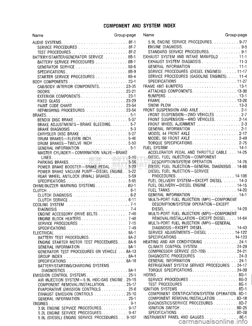
COMPONENT AND SYSTEM INDEX
Name
Group-page
AUDIO
SYSTEMS
8F-1
SERVICE
PROCEDURES 8F-7
TEST PROCEDURES 8F-2
BATTERY/STARTER/GENERATOR SERVICE 8B-1 BATTERY SERVICE PROCEDURES 8B-1
GENERATOR SERVICE 8B-6
SPECIFICATIONS 8B-9
STARTER SERVICE PROCEDURES 8B-4
BODY COMPONENTS 23-1 CAB/BODY INTERIOR COMPONENTS
23-35
DOORS
23-21
EXTERIOR COMPONENTS 23-1
FIXED GLASS
23-29
PAINT
CODE CHART
23-54
REFINISHING PROCEDURES
23-54
BRAKES
5-1 BENDIX DISC BRAKE 5-37 BRAKE ADJUSTMENTS-BRAKE BLEEDING 5-7
BRAKE DIAGNOSIS 5-3
CHRYSLER
DISC BRAKE 5-27 DRUM BRAKES—ELEVEN INCH 5-46
DRUM BRAKES-TWELVE INCH 5-50
GENERAL INFORMATION 5-1 MASTER CYLINDER—COMBINATION VALVE-BRAKE
LINES 5-10
PARKING BRAKES 5-56
POWER BRAKE BOOSTER-BRAKE PEDAL 5-20 POWER BRAKE VACUUM PUMP-DIESEL ENGINE. . 5-22
REAR
WHEEL ANTILOCK
(RWAL)
BRAKES 5-59
SPECIFICATIONS 5-65
CHIME/BUZZER WARNING
SYSTEMS
8U-1
CLUTCH 6-1 CLUTCH DIAGNOSIS 6-2 CLUTCH SERVICE 6-11
COOLING SYSTEM 7-1
DIAGNOSIS 7-4
ENGINE ACCESSORY DRIVE BELTS 7-40
ENGINE BLOCK HEATERS 7-48
SERVICE
PROCEDURES 7-15 SPECIFICATIONS 7-49
ELECTRICAL 8A-1 BATTERY TEST PROCEDURES 8A-2
ENGINE STARTER MOTOR TEST PROCEDURES.... 8A-9
GENERAL INFORMATION 8A-1
GENERATOR TEST PROCEDURES ON VEHICLE . . . 8A-13
GROUP INDEX 8A-1
SPECIFICATIONS 8A-18
BATTERY/STARTING/CHARGING
SYSTEMS
DIAGNOSTICS 8A-1
EMISSION
CONTROL
SYSTEMS.
25-1 AIR INJECTION SYSTEM—5.9L HDC-GAS ENGINE . 25-15 COMPONENT REMOVAL/INSTALLATION 25-17 EVAPORATIVE EMISSION CONTROLS 25-6
EXHAUST EMISSION CONTROLS 25-10
GENERAL INFORMATION 25-1
ENGINES 9-1 3.9L ENGINE SERVICE PROCEDURES 9-17 5.2L ENGINE SERVICE PROCEDURES 9-47
5.9L (DIESEL) ENGINE SERVICE PROCEDURES . . . 9-107
Name
Group-page
5.9L ENGINE SERVICE PROCEDURES 9-77 ENGINE DIAGNOSIS 9-5
STANDARD SERVICE PROCEDURES 9-1
EXHAUST SYSTEM AND INTAKE MANIFOLD 11-1
EXHAUST SYSTEM DIAGNOSIS 11-3
GENERAL INFORMATION 11-1
SERVICE
PROCEDURES (DIESEL ENGINES) 11-17
SERVICE
PROCEDURES (GASOLINE ENGINES) 11-4
SPECIFICATIONS 11-27
FRAME AND BUMPERS 13-1 ATTACHED COMPONENTS 13-30
BUMPERS
13-1
FRAME 13-20
SNOW PLOW 13-3
FRONT SUSPENSION AND AXLE 2-1 FRONT SUSPENSION—2WD VEHICLES 2-7
FRONT SUSPENSION—4WD VEHICLES 2-14 FRONT WHEEL ALIGNMENT 2-3
GENERAL INFORMATION 2-1 MODEL 44 FRONT AXLE 2-17
MODEL 60 FRONT AXLE 2-49
TORQUE SPECIFICATIONS 2-75
FUEL SYSTEM 14-1 ACCELERATOR PEDAL AND THROTTLE CABLE . . . 14-25
DIESEL
FUEL INJECTION—COMPONENT DESCRIPTION/SYSTEM OPERATION 14-76
DIESEL
FUEL INJECTION-GENERAL DIAGNOSIS. . 14-88
DIESEL
FUEL INJECTION-SERVICE
PROCEDURES
14-106
FUEL DELIVERY SYSTEM-EXCEPT DIESEL 14-3
FUEL DELIVERY-DIESEL ENGINE 14-15 FUEL TANKS 14-20
GENERAL INFORMATION 14-1 MULTI-PORT FUEL INJECTION (MPI)-COMPONENT DESCRIPTION/SYSTEM OPERATION-EXCEPT
DIESEL
14-29
MULTI-PORT FUEL INJECTION
(MPlj-COMPONENT
REMOVAL/INSTALLATION-EXCEPT DIESEL .... 14-64
MULTI-PORT FUEL INJECTION (MPI)—GENERAL DIAGNOSIS-EXCEPT DIESEL 14-43
SERVICE
ADJUSTMENTS-DIESEL
14-122
SPECIFICATIONS
14-123
HEATING AND AIR CONDITIONING 24-1 CLIMATE CONTROL SYSTEM
24-29
COMPRESSOR
SERVICE
(SD-709)
24-21 DIAGNOSTIC PROCEDURES 24-3
GENERAL INFORMATION 24-1 REFRIGERANT SYSTEM SERVICE PROCEDURES . . 24-17
TORQUE SPECIFICATIONS
24-39
HORNS 8G-1
SERVICE
PROCEDURES 8G-3
TEST PROCEDURES 8G-1
IGNITION
SYSTEMS
8D-1 COMPONENT IDENTIFICATION/SYSTEM OPERATION. 8D-1
COMPONENT REMOVAL/INSTALLATION 8D-18 DIAGNOSTICS/SERVICE PROCEDURES 8D-7
IGNITION
SWITCH
8D-25
SPECIFICATIONS
8D-28
INSTRUMENT PANEL AND GAUGES 8E-1