1993 DODGE TRUCK battery
[x] Cancel search: batteryPage 926 of 1502
•
FUEL SYSTEM 14 - 107
WARNING;
DO NOT
BLEED
AIR
FROM
THE
FUEL
SYSTEM
OF A HOT
ENGINE.
DO NOT
ALLOW FUEL
TO SPRAY ONTO
THE
EXHAUST MANIFOLD WHEN
BLEEDING
AIR
FROM
THE
FUEL SYSTEM.
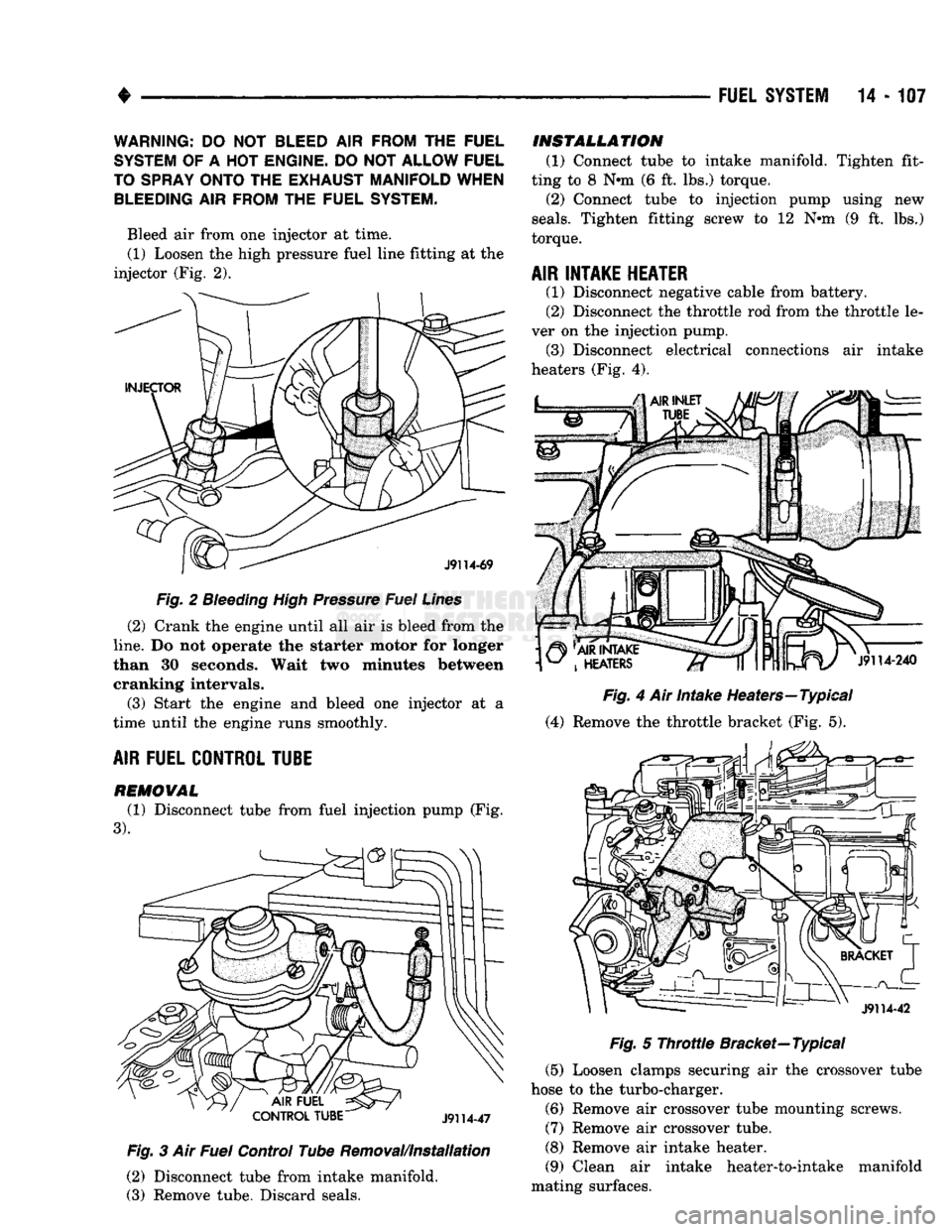
Bleed air from one injector at time. (1) Loosen the high pressure fuel line fitting at the
injector (Fig. 2).
Fig.
2
Bleeding
High Pressure Fuel Lines
(2) Crank the engine until all air is bleed from the
line.
Do not operate the starter motor for longer
than 30 seconds. Wait two minutes between cranking intervals.
(3) Start the engine and bleed one injector at a
time until the engine runs smoothly.
AIR
FUEL CONTROL TUBE
REMOWAL
(1) Disconnect tube from fuel injection pump (Fig.
3). Fig.
3 Air
Fuel
Control Tube Removal/Installation
(2) Disconnect tube from intake manifold.
(3) Remove tube. Discard seals.
INSTALLATION
(1) Connect tube to intake manifold. Tighten fit
ting to 8 Nnn (6 ft. lbs.) torque. (2) Connect tube to injection pump using new
seals.
Tighten fitting screw to 12 Nnn (9 ft. lbs.)
torque.
AIR INTAKE HEATER
(1) Disconnect negative cable from battery.
(2) Disconnect the throttle rod from the throttle le
ver on the injection pump. (3) Disconnect electrical connections air intake
heaters (Fig. 4).
Fig.
4 Air Intake Heaters—Typical
(4) Remove the throttle bracket (Fig. 5).
Fig.
5
Throttle
Bracket—Typical
(5) Loosen clamps securing air the crossover tube
hose to the turbo-charger.
(6) Remove air crossover tube mounting screws.
(7) Remove air crossover tube.
(8) Remove air intake heater.
(9) Clean air intake heater-to-intake manifold
mating surfaces.
Page 927 of 1502
(10) Install air intake heater (with new gasket) in
reverse order of removal.
AIR
INTAKE
HE
A TER
RELA YS
(1) Disconnect negative cable from battery.
(2) Disconnect electrical connections from relays
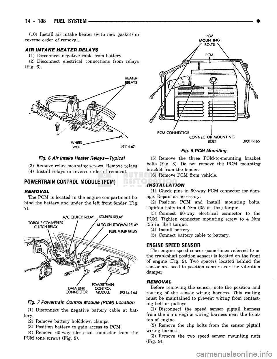
(Fig. 6).
HEATER
RELAYS
WHEEL..
WELL
J9114-67
Fig. 6 Air intake Heater Relays—Typical (3) Remove relay mounting screws. Remove relays.
(4) Install relays in reverse order of removal.
POWERTRAIN CONTROL MODULE
(PCI)
REMOWAL The PCM is located in the engine compartment be
hind the battery and under the left front fender (Fig.
7).
TORQUE CONVERTER
CLUTCH RELAY A/C CLUTCH RELAY STARTER RELAY
AUTO SHUTDOWN RELAY FUEL PUMP RELAY DATA LINK
CONNECTOR POWERTRAIN
CONTROL
MODULE
J9314-164
Fig. 7 Powertrain Control
Module
(PCM) Location (1) Disconnect the negative battery cable at bat
tery.
(2) Remove battery holddown clamps.
(3) Position battery to gain access to PCM,
(4) Remove 60-way electrical connector from the
PCM (one screw) (Fig. 8).
PCM
MOUNTING BOLTS
PCM CONNECTOR CONNECTOR MOUNTING
BOLT
J9314-165
Fig. 8 PCM Mounting (5) Remove the three PCM-to-mounting bracket
bolts (Fig. 8). Do not remove the PCM mounting
bracket from the fender.
(6) Remove PCM from vehicle.
INSTALLATION (1) Check pins in 60-way PCM connector for dam
age.
Repair as necessary.
(2) Position PCM and install mounting bolts.
Tighten bolts to 4 N*m (35 in. lbs.) torque.
(3) Connect 60-way electrical connector to the
PCM. Tighten connector mounting screw to 4 N#m (35 in. lbs.) torque. (4) Install battery. (5) Connect battery cable to battery.
ENGINE
SPEED SENSOR
The engine speed sensor (sometimes referred to as
the crankshaft position sensor) is located on the front of engine (Fig. 9). Two spacers located behind the
sensor are used to position sensor over the vibration
damper.
REMOWAL Before removing the sensor, note the position and
routing of the sensor wiring harness. This routing must be maintained to prevent wiring from contact
ing belt or pulleys.
(1) Disconnect the speed sensor pigtail harness
from the main engine wiring harness near the front/
top of engine.
(2) Remove the clip bolts from the sensor pigtail
wiring harness. (3) Remove the two speed sensor mounting nuts
(Fig. 9).
Page 929 of 1502
14
- 110
FUEL SYSTEM
SENSOR
J9114-39
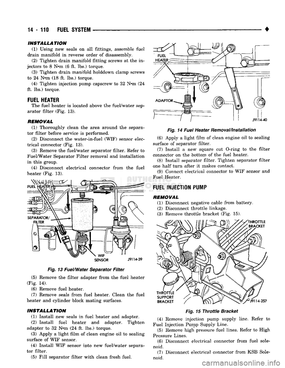
Fig.
13 Fuel/Water Separator
Filter
(5) Remove the filter adapter from the fuel heater
(Fig. 14).
(6) Remove fuel heater.
(7) Remove seals from fuel heater. Clean the fuel
heater and cylinder block mating surfaces.
INSTALLATION
(1) Install new seals in fuel heater and adapter.
(2) Install fuel heater and adapter. Tighten
adapter to 32 Nrn (24 ft. lbs.) torque. (3) Apply a light film of clean engine oil to sealing
surface of WIF sensor.
(4) Install WIF sensor into new fuel/water separa
tor filter.
(5) Fill separator filter with clean fresh fuel. •
Fig.
14
Fuel
Heater Removal/Installation (6) Apply a light film of clean engine oil to sealing
surface of separator filter.
(7) Install a new square cut O-ring to the filter
connector on the bottom of the fuel heater. (8) Install separator filter. Tighten separator filter
one half turn after it makes contact. (9) Connect electrical connector to WIF sensor and
Fuel Heater.
FUEL INJECTION PUMP
REMOVAL (1) Disconnect negative cable from battery.
(2) Disconnect throttle linkage.
(3) Remove throttle bracket (Fig. 15).
Fig.
15
Throttle
Bracket
(4) Remove injection pump supply line. Refer to
Fuel Injection Pump Supply Line.
(5) Remove high pressure fuel lines. Refer to High
Pressure Lines. (6) Disconnect electrical connector from fuel sole
noid. (7) Disconnect electrical connector from KSB Sole
noid.
INSTALLATION
(1) Using new seals on all fittings, assemble fuel
drain manifold in reverse order of disassembly. (2) Tighten drain manifold fitting screws at the in
jectors to 8 N#m (6 ft. lbs.) torque. (3) Tighten drain manifold holddown clamp screws
to 24 N*m (18 ft. lbs.) torque. (4) Tighten injection pump capscrew to 32 N#m (24
ft. lbs.) torque.
FUEL HEATER
The fuel heater is located above the fuel/water sep
arator filter (Fig. 13).
REMOVAL
(1) Thoroughly clean the area around the separa
tor filter before service is performed.
(2) Disconnect the water-in-fuel (WIF) sensor elec
trical connector (Fig. 13). (3) Remove the fuel/water separator filter. Refer to
Fuel/Water Separator Filter removal and installation
in this group.
(4) Disconnect electrical connector from the fuel
heater (Fig. 13).
Page 933 of 1502
14 - 114
FUEL
SYSTEM
• (15) Install fuel injection pump supply line. Refer
to Fuel Injection Pump Supply Line.
(16) Connect electrical connector to fuel solenoid.
(17) Connect electrical connector to KSB solenoid.
(18) Install fuel pump vent line and capscrew.
(19) Install air fuel control tube.
(20) Install throttle bracket (Fig. 15). Tighten
mounting bolts to 24 N»m (18 ft. lbs.) torque.
(21) Install throttle linkage. When connecting the
cable to the control lever, adjust the length so the le
ver has stop-to-stop movement. Refer to Accelerator
Pedal and Throttle Controls section of Group 14,
Fuel Systems.
(22) Install and adjust throttle position sensor. Re
fer to Service Adjustments.
(23) Bleed air from fuel system. Refer to High
Pressure Fuel Lines in the Air Bleeding portion of
the Diesel Fuel Injection section of Group 14, Fuel Systems. (24) Adjust the low idle speed if required. Refer to
Service Adjustments near the end of this group. (25) Inspect throttle linkage to be sure that the
control lever breaks over the full throttle position.
Adjust as necessary. Refer to Accelerator Pedal and
Throttle Cable section of Group 14, Fuel Systems.
FUEL
INJECTION
PUMP
SUPPLY
LINE
REMOVAL
(1) Disconnect negative cable from battery.
(2) Disconnect supply line at fuel/water separator
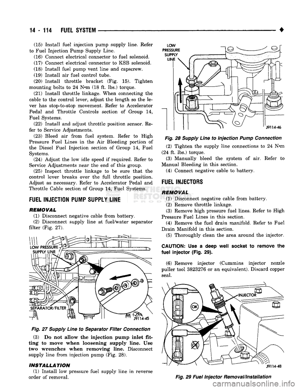
filter (Fig. 27).
Fig.
27
Supply
Line
to Separator
Filter
Connection
(3) Do not allow the injection pump inlet fit
ting to move when loosening supply line. Use two wrenches when removing line. Disconnect
supply line from injection pump (Fig. 28).
INSTALLATION
(1) Install low pressure fuel supply line in reverse
order of removal.
Fig.
28
Supply
Line
to Injection
Pump
Connection
(2) Tighten the supply line connections to 24 Nnn
(24 ft. lbs.) torque.
(3) Manually bleed the system of air. Refer to
Manual Bleeding in this section.
(4) Connect negative cable to battery.
FUEL
INJECTORS
REMOVAL
(1) Disconnect negative cable from battery.
(2) Remove throttle linkage.
(3) Remove high pressure fuel lines. Refer to High
Pressure Fuel Lines in this section. (4) Remove the fuel drain manifold. Refer to Fuel
Drain Manifold in this section. (5) Thoroughly clean the area around the injector.
CAUTION:
Use a deep
well
socket
to remove the
fuel
injector (Fig. 29).
(6) Remove injector (Cummins injector nozzle
puller tool 3823276 or an equivalent). Discard copper seal.
Fig.
29
Fuel
Injector Removal/Installation
Page 934 of 1502
FUEL SYSTEM
14 - 115
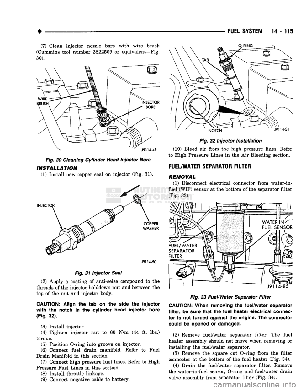
(7) Clean injector nozzle bore with wire brush
(Cummins tool number 3822509
or
equivalent—Fig.
30).
Fig.
30
Cleaning Cylinder Head Injector Bore INSTALLATION
(1) Install
new
copper seal
on
injector
(Fig. 31).
J9114-50
Fig.
31
Injector Seal
(2) Apply
a
coating
of
anti-seize compound
to the
threads
of the
injector holddown
nut and
between
the
top
of the nut and
injector body.
CAUTION:
Align
the tab on the
side
the injector
with the
notch
in the
cylinder
head
injector
bore
(Fig.
32).
(3) Install injector.
(4) Tighten injector
nut to 60 N«m (44 ft. lbs.)
torque. (5) Position O-ring into groove
on
injector.
(6) Connect fuel drain manifold. Refer
to
Fuel
Drain Manifold
in
this section.
(7) Connect high pressure fuel lines. Refer
to
High
Pressure Fuel Lines
in
this section.
(8) Install throttle linkage.
(9) Connect negative cable
to
battery.
Fig.
32
Injector
Installation
(10) Bleed
air
from
the
high pressure lines. Refer
to High Pressure Lines
in the Air
Bleeding section.
FUEL/WATER SEPARATOR FILTER
REMOVAL
(1) Disconnect electrical connector from water-in-
fuel (WIF) sensor
at the
bottom
of
the separator filter (Fig.
33).
Fig.
33
Fuel/Water Separator
Filter
CAUTION:
When
removing
the
fuel/water
separator
filter,
be
sure
that
the fuel
heater
electrical
connec
tor
is not
turned
against
the
engine.
The connector
could
be
opened
or
damaged.
(2) Remove fuel/water separator filter.
The
fuel
heater assembly should
not
move when removing
or
installing
the
fuel/water separator. (3) Remove
the
square
cut
O-ring from
the
filter
connector
at the
bottom
of the
fuel heater
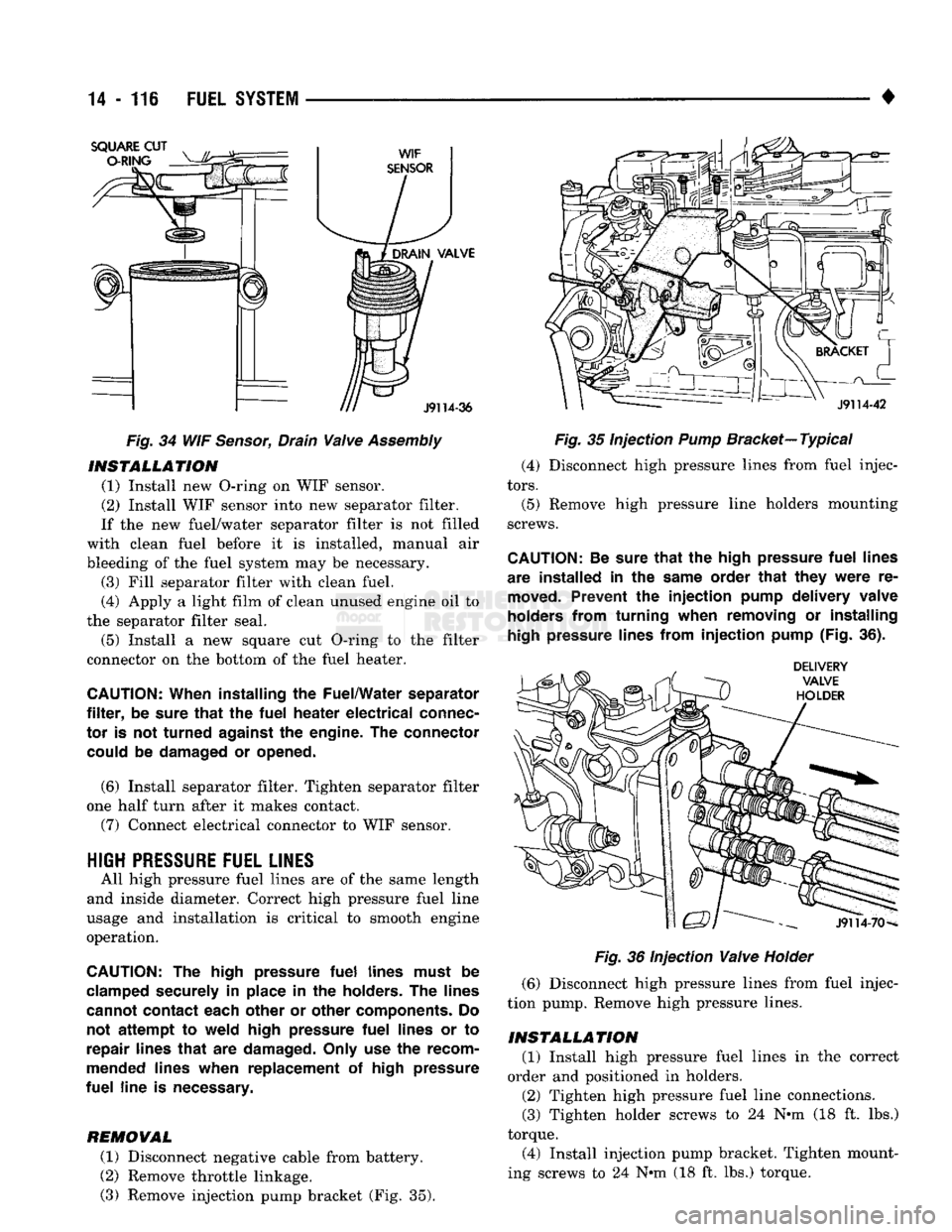
(Fig. 34).
(4) Drain
the
fuel/water separator filter. Remove
the water-in-fuel sensor, O-ring
and
fuel/water drain
valve assembly from separator filter
(Fig. 34).
Page 935 of 1502
14
• 116
FUEL
SYSTEM
Fig.
34 WIF
Sensor,
Drain
Valve
Assembly
INSTALLATION
(1) Install new O-ring on WIF sensor.
(2) Install WIF sensor into new separator filter.
If the new fuel/water separator filter is not filled
with clean fuel before it is installed, manual air
bleeding of the fuel system may be necessary. (3) Fill separator filter with clean fuel.
(4) Apply a light film of clean unused engine oil to
the separator filter seal.
(5) Install a new square cut O-ring to the filter
connector on the bottom of the fuel heater.
CAUTION:
When installing
the
Fuel/Water separator
filter,
be
sure
that
the
fuel
heater
electrical
connec
tor
is not
turned
against
the
engine.
The
connector could
be
damaged
or
opened.
(6) Install separator filter. Tighten separator filter
one half turn after it makes contact.
(7) Connect electrical connector to WIF sensor.
HIGH
PRESSURE
FUEL LINES
All high pressure fuel lines are of the same length
and inside diameter. Correct high pressure fuel line
usage and installation is critical to smooth engine
operation.
CAUTION:
The
high pressure
fuel
lines must
be
clamped securely
in
place
in the
holders.
The
lines
cannot contact each other
or
other components.
Do
not
attempt
to
weld high pressure
fuel
lines
or to
repair lines
that
are
damaged. Only
use the
recom
mended lines when replacement
of
high pressure
fuel
line
is
necessary.
REMOVAL
(1) Disconnect negative cable from battery.
(2) Remove throttle linkage.
(3) Remove injection pump bracket (Fig. 35).
Fig.
35 Injection
Pump
Bracket—
Typical
(4) Disconnect high pressure lines from fuel injec
tors.
(5) Remove high pressure line holders mounting
screws.
CAUTION:
Be
sure
that
the
high pressure
fuel
lines
are installed
in the
same order
that
they
were
re
moved.
Prevent
the
injection
pump delivery valve
holders from turning when removing
or
installing
high
pressure lines from
injection
pump (Fig.
36).
Fig.
36 Injection
Valve
Holder
(6) Disconnect high pressure lines from fuel injec
tion pump. Remove high pressure lines.
INSTALLATION
(1) Install high pressure fuel lines in the correct
order and positioned in holders.
(2) Tighten high pressure fuel line connections.
(3) Tighten holder screws to 24 N-m (18 ft. lbs.)
torque.
(4) Install injection pump bracket. Tighten mount
ing screws to 24 N*m (18 ft. lbs.) torque.
Page 938 of 1502
•
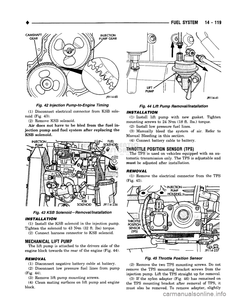
Fig. 42 Injection
Pump-to-Engine
Timing
(1) Disconnect electrical connector from KSB sole
noid (Fig. 43).
(2) Remove KSB solenoid.
Air does not have to be Med from the fuel in
jection pump and fuel system after replacing the KSB solenoid.
Fig. 43 KSB Solenoid—Removal/installation INSTALLATION
(1) Install the KSB solenoid in the injection pump.
Tighten the solenoid to 43 N*m (32 ft. lbs) torque. (2) Connect harness connector to KSB solenoid.
MECHANICAL
LIFT
PUMP
The lift pump is attached to the drivers side of the
engine block towards the rear of the engine (Fig. 44).
REMOVAL (1) Disconnect negative battery cable at battery.
(2) Disconnect low pressure fuel lines from pump
(Fig. 44).
(3) Remove lift pump mounting screws.
(4) Clean mating surfaces on lift pump and engine
block.
FUEL
SYSTEM
14 - 119
Fig.
44 Lift
Pump
Removal/Installation INSTALLATION
(1) Install lift pump with new gasket. Tighten
mounting screws to 24 N#m (18 ft. lbs.) torque.
(2) Install low pressure fuel lines.
(3) Manually bleed the system of air. Refer to
Manual Bleeding in this section. (4) Connect battery cable to battery.
THROTTLE
POSITION
SENSOR
(TPS) The TPS is used on vehicles equipped with an au
tomatic transmission only. The TPS is adjustable and
must be adjusted after installation.
REMOVAL (1) Remove the electrical connector from the TPS
(Fig. 45).
Fig.
45
Throttle
Position
Sensor
(2) Remove the two TPS mounting screws. Do not
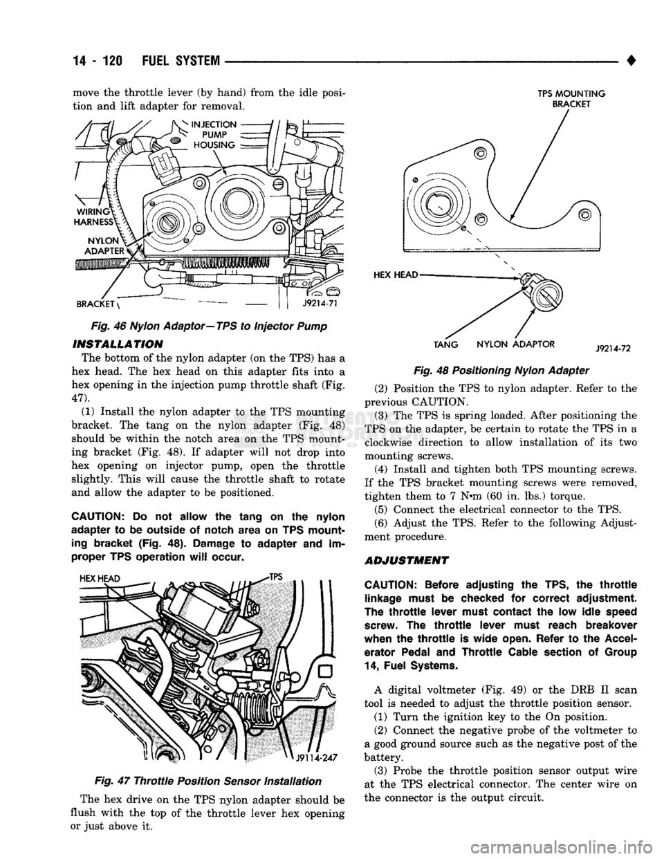
remove the TPS mounting bracket screws from the injection pump. Lift the TPS straight up for removal. (3) If the nylon adapter (Fig. 46) has remained on
the TPS mounting bracket after removal of TPS, it
must also be removed. To remove adapter, slightly
Page 939 of 1502
14-120
FUEL
SYSTEM
• move the throttle lever (by hand) from the idle posi
tion and lift adapter for removal. Fig. 46
Nylon
Adaptor—TPS to Injector Pump
INSTALLATION
The bottom of the nylon adapter (on the TPS) has a
hex head. The hex head on this adapter fits into a
hex opening in the injection pump throttle shaft (Fig.
47).
(1) Install the nylon adapter to the TPS mounting
bracket. The tang on the nylon adapter (Fig. 48) should be within the notch area on the TPS mount
ing bracket (Fig. 48). If adapter will not drop into
hex opening on injector pump, open the throttle slightly. This will cause the throttle shaft to rotate
and allow the adapter to be positioned.
CAUTION:
Do not allow the tang on the nylon
adapter to be outside of notch area on TPS mount
ing
bracket (Fig. 48).
Damage
to adapter and im
proper TPS operation
will
occur.
Fig.
47
Throttle
Position
Sensor
Installation
The hex drive on the TPS nylon adapter should be
flush with the top of the throttle lever hex opening or just above it.
TPS
MOUNTING
BRACKET
TANG
NYLON
ADAPTOR
Fig. 48 Positioning
Nylon
Adapter (2) Position the TPS to nylon adapter. Refer to the
previous CAUTION.
(3) The TPS is spring loaded. After positioning the
TPS on the adapter, be certain to rotate the TPS in a clockwise direction to allow installation of its two
mounting screws.
(4) Install and tighten both TPS mounting screws.
If the TPS bracket mounting screws were removed,
tighten them to 7 N»m (60 in. lbs.) torque.
(5) Connect the electrical connector to the TPS.
(6) Adjust the TPS. Refer to the following Adjust
ment procedure.
ADJUSTMENT
CAUTION:
Before adjusting the TPS, the
throttle
linkage
must
be checked for correct adjustment.
The
throttle
lever
must
contact the low idle
speed
screw.
The
throttle
lever
must
reach breakover
when the
throttle
is wide
open.
Refer to the
Accel
erator Pedal and
Throttle
Cable
section
of
Group
14,
Fuel
Systems.
A digital voltmeter (Fig. 49) or the DRB II scan
tool is needed to adjust the throttle position sensor. (1) Turn the ignition key to the On position.
(2) Connect the negative probe of the voltmeter to
a good ground source such as the negative post of the
battery.
(3) Probe the throttle position sensor output wire
at the TPS electrical connector. The center wire on
the connector is the output circuit.