1993 DODGE TRUCK change wheel
[x] Cancel search: change wheelPage 155 of 1502
3
- 28
REAR
SUSPENSION
AND
AXLE
•
SURE-GRIP
DIFFERENTIAL
SERVICE
GENERAL
INFORMATION
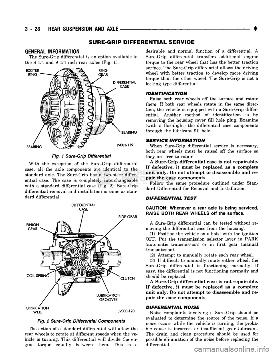
The Sure-Grip differential
is an
option available
in
the
8 1/4 and 9 1/4
inch rear axles
(Fig. 1).
EXCITER
RING RING
GEAR
DIFFERENTIAL
CASE
BEARING BEARING
J9003-119
Fig.
1
Sure-Grip
Differential
With
the
exception
of the
Sure-Grip differential
case,
all the
axle components
are
identical
to the
standard axle.
The
Sure-Grip
has a
two-piece differ
ential case.
The
case
is
completely interchangeable
with
a
standard differential case
(Fig. 2).
Sure-Grip differential removal
and
installation
is
same
as
stan
dard differential.
DIFFERENTIAL
CASE
PINION
GEAR
COIL SPRING LUBRICATION
WELL
SIDE
GEAR
CLUTCH
LUBRICATION
GROOVES
J9003-120
Fig.
2
Sure-Grip
Differential
Components
The action
of a
standard differential will allow
the
rear wheels
to
rotate
at
different speeds when
the ve
hicle
is
turning. This differential will divide
the en
gine torque equally between them. This
is a
desirable
and
normal function
of a
differential.
A
Sure-Grip differential transfers additional engine
torque
to the
rear wheel that
has the
better traction surface.
The
Sure-Grip differential allows
the
driving
wheel with better traction
to
develop more driving
torque than
the
other wheel.
The
Sure-Grip
is not a
locking type differential.
IDENTIFICATION Raise both rear wheels
off the
surface
and
rotate
them.
If
both rear wheels rotate
in the
same direc
tion,
the
vehicle
is
equipped with
a
Sure-Grip differ ential. Another method
of
identification
is by
removing
the
housing cover fill hole plug. Examine (with
a
flashlight)
the
differential case components
through
the
lubricant fill hole.
SERVICE INFORMATION When Sure-Grip differential service
is
necessary,
both rear wheels must
be
raised
off the
surface
so
they
are
free
to
rotate.
A Sure-Grip differential case
is not
repairable.
If defective,
it
must
be
replaced
as a
complete
unit only.
Do not
attempt
to
disassemble
and re
pair
the
case components.
Follow
the
same procedure outlined under Stan
dard Differential
for
Removal
and
Installation.
DIFFERENTIAL TEST
CAUTION:
Whenever
a
rear axle
is
being
serviced,
RAISE
BOTH
REAR
WHEELS
off the
surface.
A Sure-Grip differential
can be
tested without
re
moving
the
differential case from
the
housing.
(1) Position
the
vehicle
on a
hoist with
the
ignition
OFF.
Put the
transmission selector lever
in
PARK
(automatic transmission)
or in
first gear (manual
transmission).
(2) Attempt
to
manually rotate each rear wheel.
(3)
If
difficult
to
manually rotate either wheel,
the
Sure-Grip differential
is
functioning normally.
If
easy,
the
differential
is not
functioning normally
and
should
be
replaced.
A Sure-Grip differential case
is not
repairable.
If defective,
it
must
be
replaced
as a
complete
unit only.
Do not
attempt
to
disassemble
and re
pair
the
case components.
DIFFERENTIAL NOISE Noise complaints involving
a
Sure-Grip should
be
evaluated
to
determine
the
source
of the
noise.
If a
noise occurs while
the
vehicle
is
turning,
the
proba
ble cause
is
incorrect
or
insufficient gear lubricant. The drain
and
clean procedure should
be
used
for
possible elimination
of the
noise before replacing
the
differential.
Page 192 of 1502

•
BRAKES
5 - 5 Disc brake rotors with excessive lateral runout or
thickness variation, or out of round brake drums are
the primary causes of pulsation. Other causes are loose
wheel bearings or calipers and worn, damaged tires.
PULL A
front pull condition could be the result of con
taminated lining in one caliper, seized caliper piston,
binding caliper, loose caliper, loose or corroded slide
pins,
improper brakeshoes, or a damaged rotor.
A worn, damaged wheel bearing or suspension compo
nent are further causes of pull. A damaged front tire (bruised, ply separation) can also cause pull.
A common and frequently misdiagnosed pull condi
tion is where direction of pull changes after a few
stops.
The cause is a combination of brake drag fol
lowed by fade at one of the brake units.
As the dragging brake overheats, efficiency is so
reduced that fade occurs. Since the opposite brake
unit is still functioning normally, its braking effect is
magnified. This causes pull to switch direction in fa
vor of the normally functioning brake unit.
When diagnosing a change in pull condition, re
member that pull will return to the original direction
if the dragging brake unit is allowed to cool down (and is not seriously damaged).
REAR BRAKE GRAB
OR
PULL
Rear grab or pull is usually caused by an improperly
adjusted or seized parking brake cable, contaminated
lining, bent or binding shoes and support plates, or im
properly assembled components. This is particularly
true when only one rear wheel is involved. However,
when both rear wheels are affected, the master cylinder or proportioning valve could be at fault.
BRAKES
DO NOT
HOLD
AFTER
DRIVING
THROUGH
DEEP
WATER
PUDDLES
This condition is generally caused by water soaked
lining. If the lining is only wet, it can be dried by driv
ing with the brakes very lightly applied for a few min
utes.
However, if the lining is thoroughly wet and dirty,
disassembly and cleaning will be necessary.
BRAKE NOISE
Squeak/Squeal
Brake squeak or squeal may be due to linings that
are wet or contaminated with brake fluid, grease, or oil. Glazed linings and rotors with hard spots can also con
tribute to squeak. Dirt and foreign material embedded in the brake lining can also cause squeak/squeal.
A very loud squeak or squeal is frequently a sign of
severely worn brake lining. If the lining has worn
through to the brakeshoes in spots, metal-to-metal con
tact occurs. If the condition is allowed to continue, ro tors can become so scored that replacement is necessary.
Thump/Clunk
Thumping or clunk noises during braking are fre
quently not caused by brake components. In many
cases,
such noises are caused by loose or damaged steering, suspension, or engine components. How
ever, calipers that bind on the slide pins, or slide sur
faces,
can generate a thump or clunk noise. Worn
out, improperly adjusted, or improperly assembled
rear brakeshoes can also produce a thump noise.
Chatter
Brake chatter is usually caused by loose or worn
components, or glazed/burnt lining. Rotors with hard
spots can also contribute to chatter. Additional
causes of chatter are out of tolerance rotors, brake
lining not securely attached to the shoes, loose wheel
bearings and contaminated brake lining.
Brakelining Contamination Brakelining contamination is usually a product of
leaking calipers or wheel cylinders, driving through
deep water puddles, or lining that has become cov
ered with grease and grit during repair.
Wheel and
Tire
Problems Some conditions attributed to brake components
may actually be caused by a wheel or tire problem.
A damaged wheel can cause shudder, vibration and
pull. A worn or damaged tire can also cause pull.
Severely worn tires with very little tread left can
produce a grab-like condition as the tire loses and re covers traction. Flat-spotted tires can cause vibration and wheel
tramp and generate shudder during brake operation. A tire with internal damage such as a severe
bruise or ply separation can cause pull and vibration.
MASTER
CYLINDER/POWER BOOSTER TEST
(1) Start engine and check booster vacuum hose
connections. Hissing noise indicates a vacuum leak. Correct any leaks before proceeding. (2) Stop engine and shift transmission into Neu
tral (3) Pump brake pedal until all vacuum reserve in
booster is depleted. (4) Press and hold brake pedal under light foot
pressure. (a) If pedal holds firm, proceed to step (5).
(b) If pedal does not hold firm and falls away,
master cylinder is faulty (internal leakage). (5) Start engine and note pedal action. (a) If pedal falls away slightly under light foot
pressure then holds firm, proceed to step (6). (b) If pedal is effort is high, or no pedal action is
discernible, power booster or vacuum check valve is
faulty. Install known good check valve and repeat steps (2) through (5).
Page 200 of 1502
•
BRAKES
5 - 13
COMBINATION VALVE OPERATION
METERING (HOLD-OFF) VALVE The metering valve is used to balance brake action
between the front disc and rear drum brakes. The
valve meters (holds-off) full apply pressure to the front disc brakes until the rear brakeshoes are in full
contact with the drums.
The valve is designed to maintain front brake fluid
pressure at 3-30 psi until the hold-off limit of 117 psi is reached. At this point, the metering valve opens completely permitting full fluid apply pressure to the
front disc brakes.
PRESSURE DIFFERENTIAL SWITCH AND VALVE The pressure differential switch is connected to the
brake warning light. The switch is triggered by movement of the switch valve. The purpose of the switch is to monitor fluid pressure in the separate
front/rear brake hydraulic circuits.
A decrease or loss of fluid pressure in either hy
draulic circuit will cause the switch valve to shuttle
forward or rearward in response to a pressure differ ential.
Movement of the switch valve will push the switch
plunger upward. This closes the switch internal con tacts completing the electrical circuit to the warning light. The switch valve will remain in an actuated
position until repair restores system pressures to nor mal levels.
COMBINATION VALVE TESTING
TESTING METERING VALVE Metering valve operation can be checked visually
and with the aid of a helper.
Observe the metering valve stem while a helper
applies and releases the brakes. If the valve is oper
ating correctly, the stem will extend slightly when
the brakes are applied and retract when the brakes are released.
If the valve is faulty, replace the entire combina
tion valve as an assembly.
TESTING PRESSURE DIFFERENTIAL SWITCH (1) Have helper sit in drivers seat to observe brake
warning light and to operate brake pedal.
(2) Raise vehicle on hoist.
(3) Connect bleed hose to left or right rear wheel
cylinder. Then immerse hose end in glass jar par
tially filled with brake fluid.
(4) Have helper press and hold brake pedal all the
way down and observe warning light.
(a) If warning light illuminates, switch is operat
ing correctly. (b) If light fails to illuminate, check circuit fuse,
bulb and wiring. Repair as necessary and repeat test steps (3) and (4). (5) If warning light still fails to illuminate, check
brakelight and park brake switches (and wiring) with test lamp. Repair or replace parts as necessary and test differential pressure switch operation again.
(6) If warning light still does not illuminate,
switch is faulty. Replace combination valve, bleed
brakes and verify proper switch and valve operation.
COMBINATION VALVE REMOVAL/INSTALLATION
VALVE REMOVAL (1) Raise vehicle on hoist.
(2) Mark or tag brake lines connected to valve for
assembly reference.
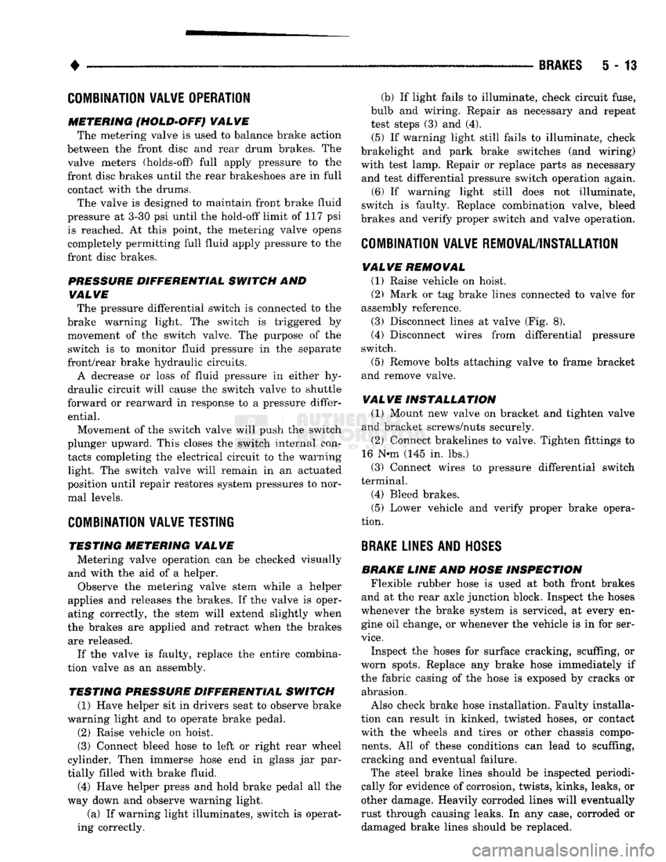
(3) Disconnect lines at valve (Fig. 8).
(4) Disconnect wires from differential pressure
switch.
(5) Remove bolts attaching valve to frame bracket
and remove valve.
VALVE INSTALLATION (1) Mount new valve on bracket and tighten valve
and bracket screws/nuts securely.
(2) Connect brakelines to valve. Tighten fittings to
16 N*m (145 in. lbs.)
(3) Connect wires to pressure differential switch
terminal. (4) Bleed brakes.
(5) Lower vehicle and verify proper brake opera
tion.
BRAKE
LINES AND
HOSES
BRAKE LINE AND HOSE INSPECTION Flexible rubber hose is used at both front brakes
and at the rear axle junction block. Inspect the hoses
whenever the brake system is serviced, at every en gine oil change, or whenever the vehicle is in for ser
vice.
Inspect the hoses for surface cracking, scuffing, or
worn spots. Replace any brake hose immediately if
the fabric casing of the hose is exposed by cracks or abrasion.
Also check brake hose installation. Faulty installa
tion can result in kinked, twisted hoses, or contact with the wheels and tires or other chassis compo
nents.
All of these conditions can lead to scuffing,
cracking and eventual failure.
The steel brake lines should be inspected periodi
cally for evidence of corrosion, twists, kinks, leaks, or
other damage. Heavily corroded lines will eventually
rust through causing leaks. In any case, corroded or damaged brake lines should be replaced.
Page 224 of 1502
•
BRAKES
5 - 37
BENDIX
DISC
BRAKE
INDEX
page
Caliper Overhaul
41
Disc
Brake Inspection
39
Disc
Brakeshoe
Installation
40
Disc
Brakeshoe Removal
. 39
GENERAL
SERVICE
INFORMATION
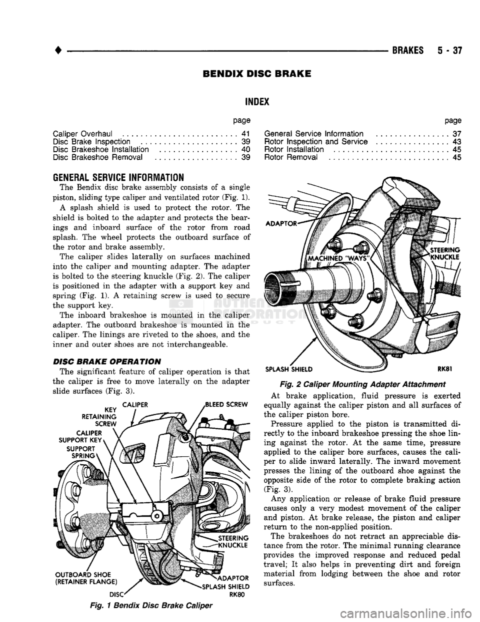
The Bendix disc brake assembly consists of a single
piston, sliding type caliper and ventilated rotor (Fig. 1). A splash shield is used to protect the rotor. The
shield is bolted to the adapter and protects the bear
ings and inboard surface of the rotor from road splash. The wheel protects the outboard surface of
the rotor and brake assembly. The caliper slides laterally on surfaces machined
into the caliper and mounting adapter. The adapter
is bolted to the steering knuckle (Fig. 2). The caliper
is positioned in the adapter with a support key and spring (Fig. 1). A retaining screw is used to secure
the support key. The inboard brakeshoe is mounted in the caliper
adapter. The outboard brakeshoe is mounted in the
caliper. The linings are riveted to the shoes, and the
inner and outer shoes are not interchangeable.
DISC
BRAKE OPERATION
The significant feature of caliper operation is that
the caliper is free to move laterally on the adapter slide surfaces (Fig. 3).
Fig.
1
Bendix
Disc
Brake Caliper
page
General Service
Information
37
Rotor Inspection
and
Service
................ 43
Rotor
Installation
45
Rotor Removal
45
Fig.
2 Caliper
Mounting
Adapter Attachment
At brake application, fluid pressure is exerted
equally against the caliper piston and all surfaces of
the caliper piston bore.
Pressure applied to the piston is transmitted di
rectly to the inboard brakeshoe pressing the shoe lin ing against the rotor. At the same time, pressure applied to the caliper bore surfaces, causes the cali
per to slide inward laterally. The inward movement
presses the lining of the outboard shoe against the
opposite side of the rotor to complete braking action (Fig. 3).
Any application or release of brake fluid pressure
causes only a very modest movement of the caliper and piston. At brake release, the piston and caliper
return to the non-applied position.
The brakeshoes do not retract an appreciable dis
tance from the rotor. The minimal running clearance
provides the improved response and reduced pedal
travel; It also helps in preventing dirt and foreign
material from lodging between the shoe and rotor surfaces.
Page 353 of 1502
8D
- 2
IGNITION
SYSTEMS
•
A/C
CLUTCH RELAY STARTER RELAY
DATA LINK CONTROL
CONNECTOR
MODULE J9314-164
Fig.
1
Auto
Shut Down
Relay
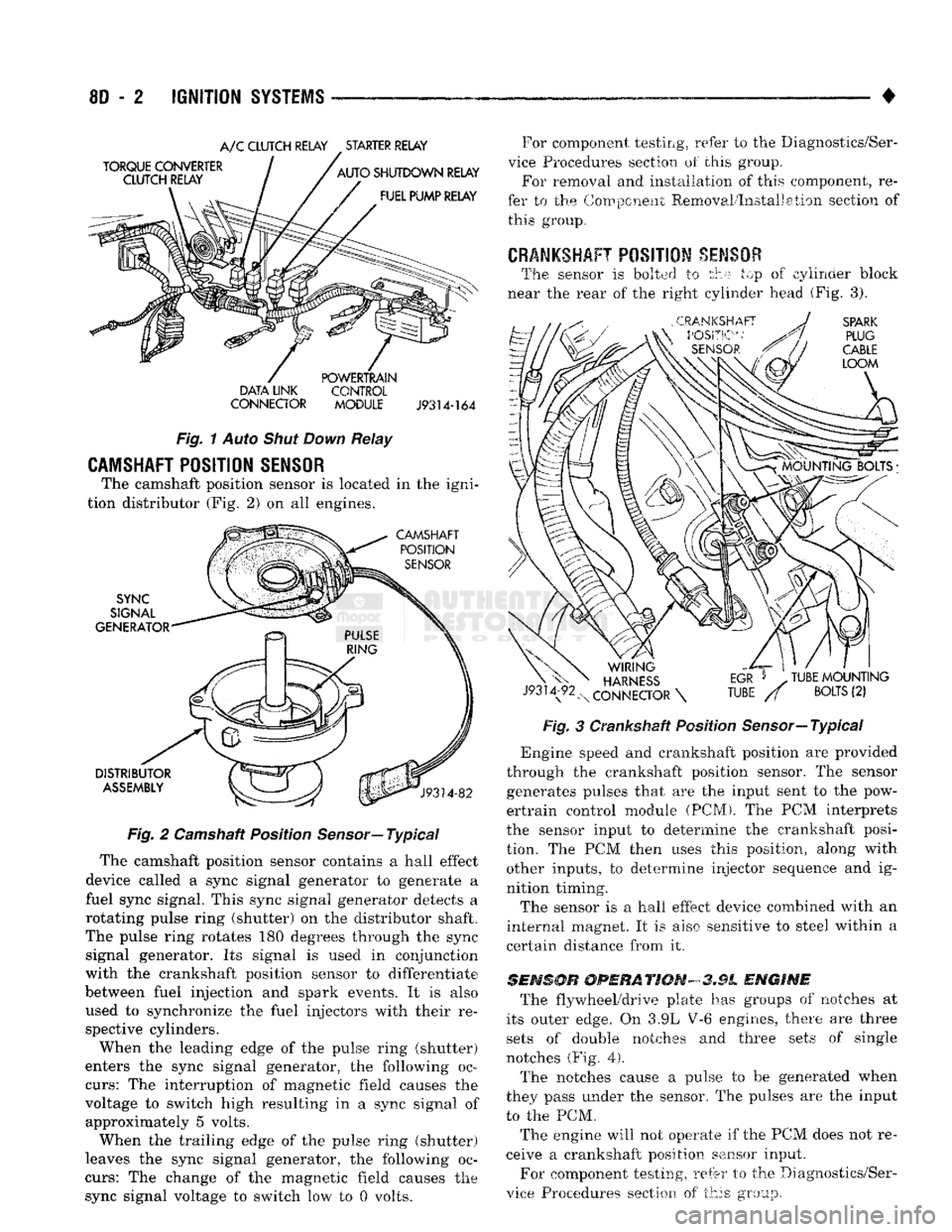
CAMSHAFT POSITION SENSOR
The camshaft position sensor is located in the igni
tion distributor (Fig. 2) on all engines.
Fig.
2 Camshaft Position
Sensor—
Typical
The camshaft position sensor contains a hall effect
device called a sync signal generator to generate a
fuel sync signal. This sync signal generator detects a
rotating pulse ring (shutter) on the distributor shaft.
The pulse ring rotates 180 degrees through the sync signal generator. Its signal is used in conjunction
with the crankshaft position sensor to differentiate
between fuel injection and spark events. It is also
used to synchronize the fuel injectors with their re spective cylinders.
When the leading edge of the pulse ring (shutter)
enters the sync signal generator, the following oc
curs:
The interruption of magnetic field causes the
voltage to switch high resulting in a sync signal of approximately 5 volts.
When the trailing edge of the pulse ring (shutter)
leaves the sync signal generator, the following oc
curs:
The change of the magnetic field causes the sync signal voltage to switch low to 0 volts. For component testing, refer to the Diagnostics/Ser
vice Procedures section of this group. For removal and installation of this component, re
fer to the Component Removal/Installation section of this group.
CRANKSHAFT
POSITION
SENSOR
The sensor is bolted to the top of cylinder block
near the rear of the right cylinder head (Fig. 3).
Fig.
3 Crankshaft Position Sensor—Typical
*
Engine speed and crankshaft position are provided
through the crankshaft position sensor. The sensor generates pulses that are the input sent to the pow
ertrain control module (PCM). The PCM interprets
the sensor input to determine the crankshaft posi
tion. The PCM then uses this position, along with other inputs, to determine injector sequence and ig
nition timing.
The sensor is a hall effect device combined with an
internal magnet. It is also sensitive to steel within a
certain distance from it.
SENSOR
OPERATION-3.9L
ENGINE
The flywheel/drive plate has groups of notches at
its outer edge. On 3.9L V-6 engines, there are three sets of double notches and three sets of single
notches (Fig.
4).
The notches cause a pulse to be generated when
they pass under the sensor. The pulses are the input to the PCM.
The engine will not operate if the PCM does not re
ceive a crankshaft position sensor input.
For component testing, refer to the Diagnostics/Ser
vice Procedures section of this group.
Page 448 of 1502
•
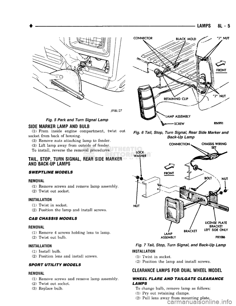
LAMPS
8L - 5
J918L-27
Fig.
5
Park
and Turn
Signal
Lamp
SIDE MARKER LAMP AND BULB
(1) From inside engine compartment, twist out
socket from back of housing. (2) Remove nuts attaching lamp to fender. (3) Lift lamp away from outside of fender.
To install, reverse the removal procedures.
TAIL,
STOP, TURN
SIGNAL,
REAR SIDE MARKER
AND BACK-UP LAMPS
SWEPTLINE MODELS
REMOVAL
(1) Remove screws and remove lamp assembly.
(2) Twist out socket.
INSTALLATION (1) Twist in socket.
(2) Position the lamp and install screws.
CAB CHASSIS MODELS
REMOVAL (1) Remove 4 screws holding lens to lamp. (2) Twist out bulb.
INSTALLATION (1) Install bulb.
(2) Position lens and install screws.
SPORT UTILITY MODELS
REMOVAL
(1) Remove screws and remove lamp assembly.
(2) Twist out socket. (3) Replace bulb.
Fig.
6
Tail,
Stop,
Turn
Signal,
Rear
Side
Marker and
Back-Up
Lamp
LAMP
ASSEMBLY
PR1086
Fig.
7
Tail,
Stop,
Turn
Signal,
and
Back-Up
Lamp
INSTALLATION
(1) Twist in socket. (2) Position the lamp and install screws.
CLEARANCE LAMPS
FOR
DUAL WHEEL MODEL
WHEEL FLARE AND TAILGATE CLEARANCE
LAMPS
To change bulb, remove lamp as follows: (1) Pry out retaining clamps.
(2) Pull lens away from mounting plate.
Page 449 of 1502
8L
- 6
LAMPS
•
ASSEMBLY
* J908L-63
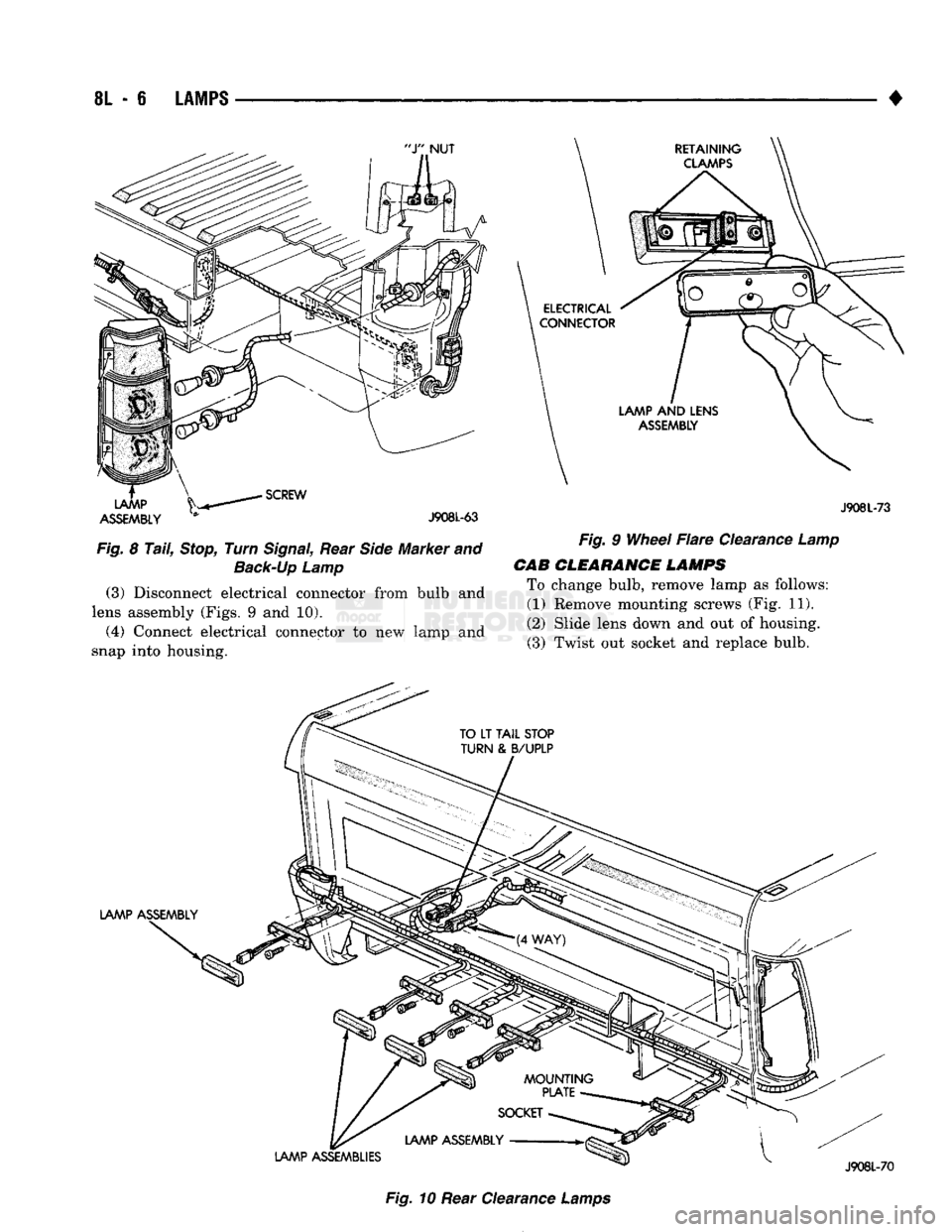
Fig.
8
Tail,
Stop,
Turn
Signal,
Rear
Side
Marker and
Back-Up
Lamp
(3)
Disconnect electrical connector from bulb and
lens assembly (Figs. 9 and 10).
(4) Connect electrical connector to new lamp and
snap into housing. J908L-73
Fig.
9
Wheel
Flare
Clearance
Lamp
CAB
CLEARANCE LAMPS
To change bulb, remove lamp as follows: (1) Remove mounting screws (Fig. 11).
(2) Slide lens down and out of housing. (3) Twist out socket and replace bulb.
Fig.
10 Rear Clearance
Lamps
Page 612 of 1502
•
ENGINES
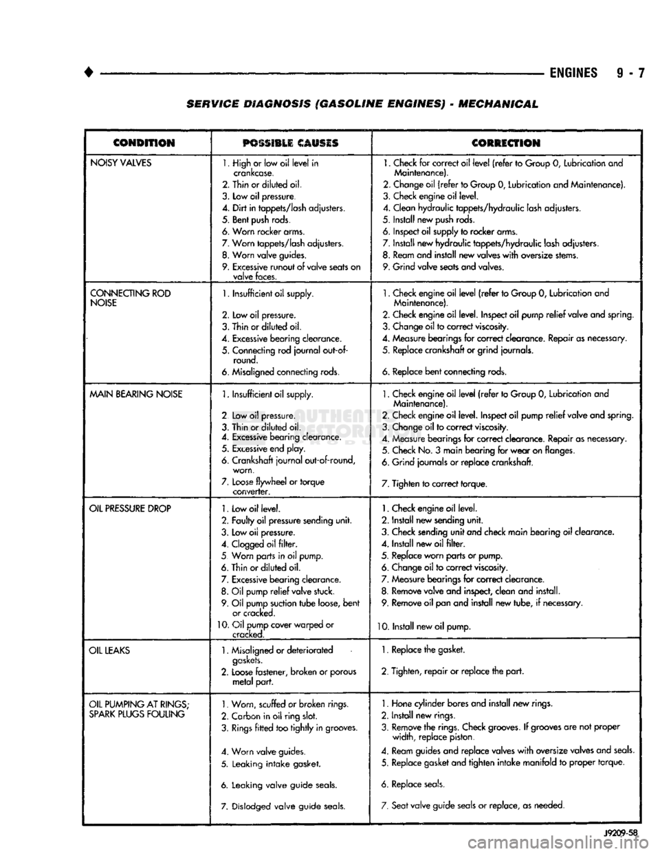
9 - 7 SERVICE DIAGNOSIS (GASOLINE ENGINES) - MECHANICAL
CONDITION
PSSSI1LI
CAUSIS
CORRECTION
NOISY
VALVES
1. High
or
low oil
level
in
crankcase.
2. Thin or
diluted
oil.
3.
Low
oil
pressure.
4.
Dirt
in
tappets/lash
adjusters.
5. Bent
push
rods.
6. Worn rocker arms.
7.
Worn
tappets/lash
adjusters.
8.
Worn
valve
guides.
9.
Excessive
runout
of
valve
seats
on
valve
faces.
1.
Check
for
correct oil
level
(refer
to
Group
0,
Lubrication and
Maintenance).
2. Change oil
(refer
to Group
0,
Lubrication and Maintenance).
3. Check engine oil level.
4. Clean hydraulic tappets/hydraulic lash adjusters.
5. Install new
push
rods.
6. Inspect oil supply to rocker arms.
7. Install new hydraulic tappets/hydraulic lash adjusters. 8. Ream and install new valves
with
oversize stems.
9. Grind valve seats and valves.
CONNECTING
ROD
NOISE
1.
Insufficient oil supply.
2.
Low oil
pressure.
3.
Thin
or
diluted
oil.
4.
Excessive
bearing
clearance.
5. Connecting rod
journal
out-of- round.
6. Misaligned connecting rods.
1.
Check engine oil
level
(refer
to Group
0,
Lubrication and
Maintenance).
2. Check engine oil level. Inspect oil pump
relief
valve and spring.
3. Change oil to correct
viscosity.
4. Measure bearings for correct clearance. Repair as necessary, 5. Replace crankshaft or grind journals.
6.
Replace
bent
connecting rods.
MAIN
BEARING
NOISE
1.
Insufficient oil supply.
2 Low
oil
pressure.
3. Thin or
diluted
oil.
4.
Excessive
bearing clearance. 5.
Excessive
end play.
6. Crankshaft
journal
out-of-round, worn,
7.
Loose
flywheel
or
torque
converter.
1.
Check engine oil
level
(refer
to Group
0,
Lubrication and
Maintenance).
2. Check engine oil level. Inspect oil pump
relief
valve and spring.
3. Change oil to correct
viscosity.
4. Measure bearings for correct clearance. Repair as necessary. 5. Check No.
3
main bearing for
wear
on flanges.
6. Grind journals
or
replace crankshaft.
7. Tighten to correct torque.
OIL
PRESSURE
DROP
1.
Low oil level.
2. Faulty oil pressure sending
unit.
3. Low
oil
pressure.
4.
Clogged
oil
filter.
5 Worn parts in
oil
pump.
6. Thin or
diluted
oil.
7.
Excessive
bearing clearance. 8.
Oil
pump
relief
valve stuck.
9. Oil pump suction
tube
loose,
bent
or cracked.
10.
Oil pump cover warped
or
cracked.
1.
Check engine oil level.
2. Install new sending
unit.
3. Check sending
unit
and check main bearing oil clearance.
4. Install new oil
filter.
5. Replace worn parts or pump. 6. Change oil to correct
viscosity.
7. Measure bearings for correct clearance.
8. Remove valve and inspect, clean and install. 9. Remove oil pan and install new tube,
if
necessary.
10. Install new oil pump.
OIL
LEAKS
1.
Misaligned or
deteriorated
gaskets.
2.
Loose
fastener, broken
or
porous
metal
part.
1. Replace the gasket.
2. Tighten,
repair
or replace the
part.
OIL
PUMPING
AT
RINGS;
SPARK
PLUGS
FOULING
1.
Worn, scuffed
or broken
rings.
2. Carbon in oil ring
slot.
3.
Rings
fitted
too
tightly
in grooves.
4. Worn valve guides.
5. Leaking
intake
gasket.
6. Leaking valve guide
seals.
7. Dislodged valve guide
seals.
1.
Hone cylinder bores and install new rings.
2. Install new rings.
3. Remove the rings. Check
grooves.
If
grooves
are not proper width, replace piston.
4. Ream guides and replace valves
with
oversize valves and
seals.
5. Replace gasket and tighten
intake
manifold
to
proper torque.
6. Replace
seals.
7. Seat
valve guide
seals
or
replace, as needed.
J9209-58