1993 DODGE TRUCK change wheel
[x] Cancel search: change wheelPage 26 of 1502

CHASSIS LUBRICATION
For light
duty
cycle
vehicles
GVW resting
of
3 855 Kg (8,500 lbs ) and
below.
Component
Truck Models
Fittings
Service Interval Lubricant
Center Link
AD1
AD2
AD
4
2
36
000
km
(22,500
miles)
or 2
years Multi-purpose grease
-
NGLI
grade
2
EP
(Multi-Mileage Lubricant)
Drag
Link
Bali
joints
AW1 AW 2
AW
8
2
12
000
km
(7,500
miles)
or 6
months Multi-purpose grease
-
NGLI
grade
2
EP
(Multi-Mileage Lubricant)
Gearshift
Mechanism
Overdrive
4
AD1
1
36
000
km
(22,500
miles)
or 2
years Multi-purpose grease
-
NGLI
grade
2
EP
(Multi-Purpose Lubricant)
Parking Brake Ratio
Lever
Pivot
AD1 AD
2 AD 4
AW1 AW 8
—
36
000
km
(22,500
miles)
or 2
years
Multi-purpose grease
-
NGLI
grade
2
EP
(Multi-Purpose Lubricant)
Propeller Shaft
U-joint
AW1
AW2
AW 8
3
(1
Piece
rear
P/shaft)
12
000
km
(7,500
miles)
or 6
months
Multi-purpose grease
-
NGLI
grade
2
EP
(Multi-Purpose Lubricant)
Propeller Shaft
Slip
Spline
AD1 AD
2
(2
piece P/shaft)
1
36
000
km
(22,500
miles)
or 2
years. For severe
service,
every
4
800
km
(3,000
miles)
or 3
months. Daily,
if
vehicle is operated in
water
Multi-purpose grease
-
NGLI
grade
2
EP
(Multi-Purpose Lubricant)
Suspension
Ball Joints
AD1 AD
2
4
36
000
km
(22,500
miles) or 2 years
—
every
engine
oil change
for
off-highway operation Multi-purpose grease
-
NGLI
grade
2
EP
(Multi-Mileage Lubricant)
Tie Rod Ball Joints
AD1
AD2
AD4
AW1 AW
2
AW8 4
2
36
000
km
(22,500
miles)
or 2
years
12
000
km
(7,500
miles)
or 6
months. Daily,
if
vehicle is operated in
water
Multi-purpose grease
-
NGLI
grade
2
EP
(Multi-Mileage Lubricant)
NP-241 Transfer
Case
Shift
Lever Pivot
AW1
AW2
AW8
—
As
Required
Multi-purpose grease
-
NGLI
grade
2
EP
(Multi-Purpose Lubricant)
Wheel
Stop
AD1 AD
2
AD4
—
36
000
km
(22,500
miles)
or
as
required
Wax Type Lubricant
Constant
Velocity Joint
(Front
P/shaft)
AW1
AW2
AW8 1
12
000
km
(7,500
miles) Multi-purpose grease
-
NGLI
grade
2
EP
(Multi-Purpose Lubricant)
>
J9000-59
>
Page 30 of 1502

LUBRICATION
AND
MAINTENANCE
0-11
J
DRIVE-ON
HOIST
I
FRAME
CONTACT
HOIST
TWIN
POST
CHASSIS
HOIST
FLOOR
JACK
RROOD30
Fig.
8 Correct Vehicle Lifting
Locations
An axle tube
A body side sill
A steering linkage component
A drive shaft
The engine or transmission oil pan
The fuel tank
• A front suspension arm Use the correct frame rail lifting locations only
(Fig. 8).
HOIST A vehicle can be lifted with:
• A single-post, frame-contact hoist
• A twin-post, chassis hoist
• A ramp-type, drive-on hoist
When a frame-contact type hoist is used, verify
that the lifting pads are positioned properly (Fig. 8).
WARNING:
WHEN
A
SERVICE
PROCEDURE
RE
QUIRES
THE
REMOVAL
OF
THE
REAR
AXLE,
FUEL
TANK,
OR
SPARE
TIRE,
EITHER:
• PLACE ADDITIONAL WEIGHT ON THE REAR
END OF THE VEHICLE
« ATTACH THE VEHICLE TO THE HOIST
« PLACE JACK STANDS UNDER THE VEHICLE
FOR SUPPORT TO PREVENT TIPPING WHEN
THE CENTER OF BALANCE CHANGES
4WD VEHICLES A standard hoist can be used to lift a 4WD vehicle.
The hoist should be inspected for adequate clearance. The lift arms, pads or ramps should be adjusted to
ensure that there is adequate clearance (Fig. 9).
ADJUSTMENT
PAD
ii 7
MAINTAIN
CLEARANCE
HOIST
ARM
RK44
Fig.
9 Lifting 4WD Vehicle
With
Single-Post
Hoist—
Typical
When a twin-post hoist is used, a 4 x 4 x 12-inch
wood spacer also could be required. Place the wood spacer under the front axle (opposite the differential
housing). This will maintain balance and level lift ing.
CAUTION:
The
block
that
is
used must
be
secured in
a
safe manner. This
will
ensure
that
it
will
not un
balance
the
vehicle.
VEHICLE
TOWING
RECOMMENDATIONS
When it is necessary to tow a Ram Truck, the rec
ommended method is either:
• the sling-type, rear-end raised towing method; or
• the wheel-lift towing method with a tow dolly lo
cated under the front wheels. A vehicle with flat-bed hauling equipment can also
be used to transport a disabled vehicle.
SLING-TYPE
FLAT
BED
RR0OD29
Fig.
10 Tow Vehicles
With
Approved
Equipment
Page 44 of 1502
•
LUBRICATION
AND
MAINTENANCE
0 - 25
CAUTION:
Do not
over-tighten
the
drain
and fill
hole
plugs.
Over-tightening
can strip the
hole
threads
and/or crack
the
aluminum housing.
(5) Install the drain hole plug (Figs. 4 and 5) in
the transfer case. Tighten the drain hole plug to 27 N*m (20 ft-lbs) torque. (6) Fill the transfer case to the bottom edge of the
fill hole (Figs. 4 and 5) with: • MOPAR®ATF PLUS or an equivalent Dexron II®
ATF for NP241 transfer cases
• Multi-purpose gear oil (API GL-5) or engine oil (API SG, SG/CD or SG/CE) for NP205 transfer cases. (7) Install the fill hole plug (Figs. 4 and 5) in the
transfer case. Tighten the plug to 27 N«m (20 ft-lbs) torque.
(8) Remove the support and lower the vehicle.
FLUID SPECIFICATION
• MOPAR®ATF PLUS or an equivalent Dexron II®
ATF for NP241 transfer cases • Multi-purpose gear oil (API GL-5) or engine oil (API SG, SG/CD or SG/CE) for NP205 transfer cases
NP20I
MULTI-PURPOSE GEAR OIL/ENGINE
OIL
SELECTION
MULTI-PURPOSE GEAR OIL-if the anticipated
minimum temperature will: • Be above 32°C (90°F)-use SAE 140, API GL-5;
• Decrease to as low as -23°C (-10°F)-use SAE 90,
API GL-5; and • Be below -23°C (-10°F)-use SAE 80, API GL-5. ENGINE OIL—if the anticipated minimum tem
perature will be: ® Above 0°C (32°F)-use SAE 50, API SG, SG/CD or
SG/CE;
• Below 0°C (32°F)-use SAE 30, API SG, SG/CD or SG/CE.
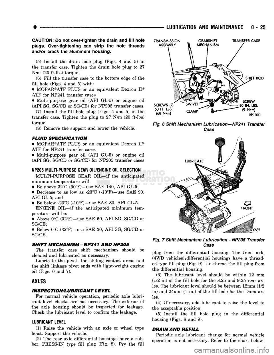
SHIFT MECHANISM-NP241 AND NP205 The transfer case shift mechanism should be
cleaned and lubricated as necessary.
Lubricate the pivot, the sliding contact areas and
the shift linkage pivot ends with light-weight engine oil (Figs. 6 and 7).
AXLES
INSPECTION/LUBRICANT LEVEL For normal vehicle operation, periodic axle lubri
cant level checks are not necessary. The exterior of
the axle housing should be inspected for leakage. Check the lubricant level to confirm the leakage.
LUBRICANT LEVEL
(1) Raise the vehicle with an axle or wheel type
hoist. Support the vehicle.
(2) The rear axle differential housings have a rub
ber, PRESS-IN type fill plug (Fig. 8). Pry the fill
TRANSMISSION
ASSEMBLY
GEARSHIFT
MECHANISM TRANSFER CASE
SCREWS
(2)
50
FT. LBS.
(68 N*m)
CLAMP
SHIFT
ROD
SCREW
80 IN.
LBS.
(9 N*m)
RP1091
Fig.
6 Shift
Mechanism
Lubrication—NP241 Transfer
Case
Fig.
RY682
7 Shift
Mechanism
Lubrication—NP205 Transfer
Case
plug from the differential housing. The front axle (4WD vehicles)*differential housings have a thread
ed-type fill plug (Fig. 9). Un-thread the fill plug from
the differential housing.
(3) The lubricant level should be within 12 mm
(1/2 in) of the fill hole for the 8.25 and 9.25 rear ax
les.
The lubricant level should be between 12mm (1/2
in) and 24mm (1 in.) of the fill hole for the Dana ax
les.
(4) If necessary, add lubricant to raise the level to
the acceptable position.
(5) Install the fill hole plug in the differential
housing (Figs. 8 and 9).
DRAIN
AND
REFILL
Periodic axle lubricant change for normal vehicle
operation is not necessary. Refer to the chart below-
Page 47 of 1502
0
- 28
LUBRICATION
AND
MAINTENANCE
•
CHASSIS AND BODY
page
Body
Component Mechanisms
32
Front
Suspension
Ball
Joints
28
Front
Wheel Bearings
29
Headlamps
32
Lower
and
Upper Suspension
Arm
Bushings
.... 30
Manual
Steering Gear
28
STEERING
LINKAGE
INSPECTION When
a
vehicle
is
raised
for
maintenance under
the vehicle,
all
steering components should
be
checked.
LUBRICATION SCHEDULE The steering linkage
is
lubricated with
a
chassis
lubricant. However,
it is
recommended that
the
link
age
be
inspected
and
lubricated after each:
•
24 000 km
(15,000 miles) interval
or
every
6
months,
for 2WD
vehicles subject
to the
LIGHT
DUTY CYCLE Maintenance Schedule
•
9 600 km
(6,000 miles) interval
or
every
6
months,
for
2WD
vehicles subject
to the
HEAVY DUTY
CY
CLE Maintenance Schedule
•
12 000 km
(7,500 miles) interval
or
every
6
months,
for 4WD
vehicles subject
to the
LIGHT DUTY CYCLE Maintenance Schedule
•
9 600 km
(6,000 miles) interval
or
every
6
months,
for
4WD
vehicles subject
to the
HEAVY DUTY
CY
CLE Maintenance Schedule.
LUBRICATION (1) Inspect
the
steering linkage
for
looseness
and
excessive wear. (2) Replace,
all
ruptured seals
and
damaged steer
ing linkage components. Damaged seals should
be re
placed
to
prevent leakage
and
contamination
of the
lubricant.
CAUTION:
Use
care
to
prevent lubricant from
con
tacting
the
brake rotors.
(3) Lubricate
the
steering linkage:
• Clean
the
Zerk type lubrication fittings
on the tie-
rod
and
center link ball-stud ends
• Lubricate
the
ball studs with MOPAR®Multi-Mile- age Lubricant
• Wipe
the
excess lubricant from
the
exterior sur
faces
of the
ball joints
page
Power
Brake System
30
Power
Steering System
. . 29
Rear
Wheel Bearings
30
Speedometer Cable
33
Steering Linkage
28
Tires
32
FRONT
SUSPENSION
BALL JOINTS
INSPECTION When
a
vehicle
is
raised
for
lubrication/general
maintenance,
the
ball joints should
be
inspected.
LUBRICATION SCHEDULE The front suspension ball joints
are
lubricated dur
ing manufacture with
a
long-life chassis lubricant.
However,
it is
recommended that
the
ball joints
be
inspected
and the
studs lubricated:
•
At
each
36 000 km
(22,500 miles) interval
or
every
2 years,
for
vehicles subject
to the
LIGHT DUTY
CY
CLE Maintenance Schedule
•
At
each
9 600 km
(6,000 miles) interval
or
every
2
years,
for
vehicles subject
to the
HEAVY DUTY
CY
CLE Maintenance Schedule.
4WD vehicles that
are
frequently driven
off-
road should
be
lubricated
at
every engine
oil
change.
LUBRICATION (1) Inspect
the
front suspension. Examine
the
ball
studs
for
looseness
and
excessive wear. (2) Replace
all
torn ball-stud seals
and
damaged
ball joints. Damaged seals should
be
replaced
to
pre vent leakage
and
contamination.
CAUTION:
Use
care
to
prevent lubricant from
con
tacting
the
brake rotors.
(3) Lubricate
the
ball studs:
• Clean
the
Zerk type lubrication fittings
on the
ball-stud ends
• Lubricate
the
ball studs with MOPAR®Multi-Mile-age Lubricant
• Wipe
the
excess lubricant from
the
exterior sur
faces
of the
ball joints
MANUAL
STEERING
GEAR
LUBRICATION Manual steering gears
are
permanently lubricated
during manufacture. Periodic lubrication
is not
nec
essary.
Page 51 of 1502
0
- 32
LUBRICATION
AND
MAINTENANCE
•
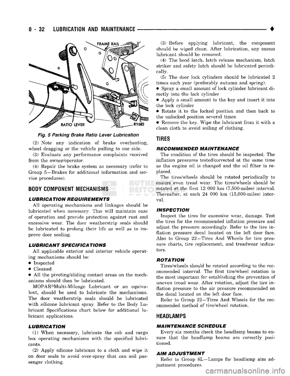
Fig.
5 Parking Brake Ratio Lever Lubrication (2) Note any indication of brake overheating,
wheel dragging or the vehicle pulling to one side.
(3) Evaluate any performance complaints received
from the owner/operator. (4) Repair the brake system as necessary (refer to
Group 5—Brakes for additional information and ser
vice procedures).
BODY
COMPONENT
MECHANISMS
LUBRICATION REQUIREMENTS
All operating mechanisms and linkages should be
lubricated when necessary. This will maintain ease of operation and provide protection against rust and
excessive wear. The door weatherstrip seals should
be lubricated to prolong their life as well as to im prove door sealing.
LUBRICANT SPECIFICATIONS
All applicable exterior and interior vehicle operat
ing mechanisms should be:
• Inspected • Cleaned
• All the pivoting/sliding contact areas on the mech anisms should then be lubricated.
MOPAR®Multi-Mileage Lubricant or an equiva
lent, should be used to lubricate the mechanisms.
The door weatherstrip seals should be lubricated
with silicone lubricant spray. Refer to the Body Lu
bricant Specifications chart below for additional lu
bricant applications.
LUBRICATION
(1) When necessary, lubricate the cab and cargo
box operating mechanisms with the specified lubri
cants.
(2) Apply silicone lubricant to a cloth and wipe it
on door seals to avoid over-spray that can soil pas
senger clothing. (3) Before applying lubricant, the component
should be wiped clean. After lubrication, any excess
lubricant should be removed.
(4) The hood latch, latch release mechanism, latch
striker and safety latch should be lubricated periodi
cally.
(5) The door lock cylinders should be lubricated 2
times each year (preferably autumn and spring): • Spray a small amount of lock cylinder lubricant di
rectly into the lock cylinder
• Apply a small amount to the key and insert it into
the lock cylinder • Rotate it to the locked position and then back to
the unlocked position several times
• Remove the key. Wipe the lubricant from it with a
clean cloth to avoid soiling of clothing.
TIRES
RECOMMENDED MAINTENANCE
The condition of the tires should be inspected. The
inflation pressures tested/corrected at the same time as the engine oil is changed and the oil filter is re
placed.
The tires/wheels should be rotated periodically to
ensure even tread wear. The tires/wheels should be
rotated at the first 12 000 km (7,500-miles) interval.
Thereafter, at each 24 000 km (15,000-miles) inter
val.
INSPECTION
Inspect the tires for excessive wear, damage. Test
the tires for the recommended inflation pressure and adjust the pressure accordingly. Refer to the tire in
flation pressure decal located on the left door face. Also to Group 22—Tires And Wheels for tire pressure charts, tire replacement, and treadwear indica
tors.
ROTATION
Tires/wheels should be rotated according to the rec
ommended interval. The first tire/wheel rotation is
the most important for establishing the prevention of uneven tread wear. After rotation, adjust the tire in
flation pressure to the air pressure recommended on
the decal located on the left door face.
Refer to Group 22—Tires And Wheels for the rec
ommended method of tire/wheel rotation.
HEADLAMPS
MAINTENANCE SCHEDULE
Every six months check the headlamp beams to en
sure that the headlamp beams are correctly posi
tioned.
AIM
ADJUSTMENT
Refer to Group 8L—Lamps for headlamp aim ad
justment procedures.
Page 56 of 1502
FRONT SUSPENSION
AND
AXLE
2 - 3
FRONT
WHEEL
ALIGNMENT
GENERAL
INFORMATION
Front wheel alignment involves
the
correct posi
tioning
of the
tire contact patch
in
relation
to the
pavement.
The
positioning
is
accomplished through
the suspension
and
steering linkage adjustments.
An
alignment
is
essential
for
efficient steering
and
direc
tional stability.
The
most important factors
of
front
end alignment
are
camber, caster
and toe
position. Routine inspection
of
the front
suspension
and
steering components
is a
good
preventative
maintenance practice.
Inspection
also
helps
to
ensure
safe operation
of the
vehicle.
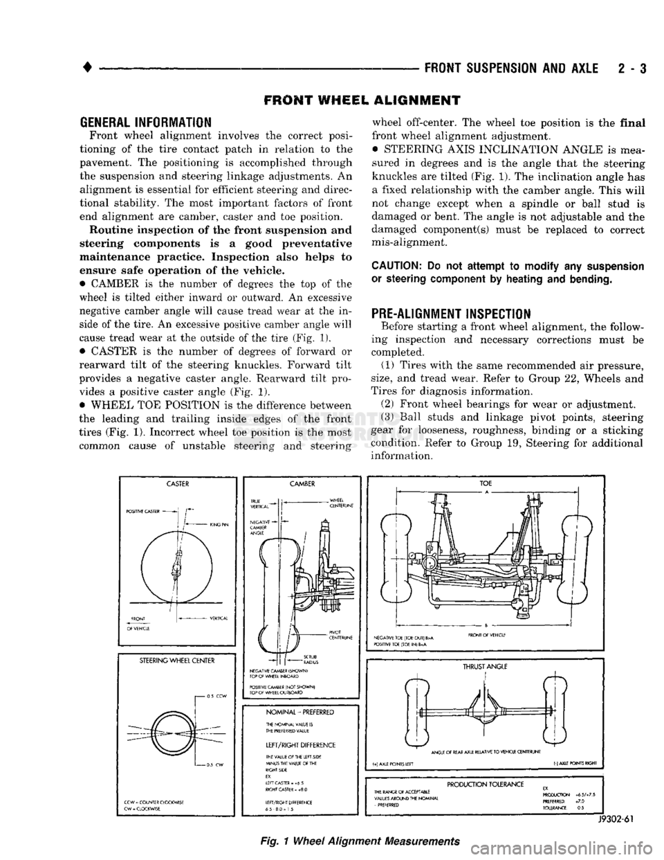
• CAMBER
is the
number
of
degrees
the top of the
wheel
is
tilted either inward
or
outward.
An
excessive
negative camber angle will cause tread wear
at the in
side
of
the tire.
An
excessive positive camber angle will
cause tread wear
at the
outside
of
the tire (Fig.
1),
• CASTER
is the
number
of
degrees
of
forward
or
rearward tilt
of the
steering knuckles. Forward tilt
provides
a
negative caster angle. Rearward tilt pro vides
a
positive caster angle
(Fig. 1).
• WHEEL
TOE
POSITION
is the
difference between
the leading
and
trailing inside edges
of the
front
tires (Fig.
1).
Incorrect wheel
toe
position
is the
most common cause
of
unstable steering
and
steering wheel off-center.
The
wheel
toe
position
is the
final
front wheel alignment adjustment. • STEERING AXIS INCLINATION ANGLE
is
mea
sured
in
degrees
and is the
angle that
the
steering
knuckles
are
tilted (Fig. 1).
The
inclination angle
has
a fixed relationship with
the
camber angle. This will
not change except when
a
spindle
or
ball stud
is
damaged
or
bent.
The
angle
is not
adjustable
and the
damaged component(s) must
be
replaced
to
correct
mis-alignment.
CAUTION:
Do not
attempt to modify
any
suspension
or steering
component
by
heating
and
bending.
PRE-ALIGNMENT INSPECTION
Before starting
a
front wheel alignment,
the
follow
ing inspection
and
necessary corrections must
be
completed.
(1)
Tires with
the
same recommended
air
pressure,
size,
and
tread wear. Refer
to
Group
22,
Wheels
and
Tires
for
diagnosis information. (2) Front wheel bearings
for
wear
or
adjustment.
(3) Ball studs
and
linkage pivot points, steering
gear
for
looseness, roughness, binding
or a
sticking
condition. Refer
to
Group
19,
Steering
for
additional information.
CASTER
POSITIVE CASTER
STEERING
WHEEL CENTER
i 0.5
CCW
0
5
CW
CCW
=
COUNTER CLOCKWISE
CW
-
CLOCKWISE
CAMBER
NEGATIVE CAMBER (SHOWN)
TOP
OF
WHEEL INBOARD
POSITIVE CAMBER
(NOT
SHOWN)
TOP
OF
WHEEL OUTBOARD
NOMINAL-PREFERRED
THE NOMINAL VALUE
IS
THE
PREFERRED
VALUE
LEFT/RIGHT
DIFFERENCE
THE VALUE
Of
THE LEFT SIDE
MINUS THE VALUE
OF
THE
RIGHT SIDE
EX.
If
FT CASTER
- +6 5
RIGHT
CASTER
»
+8.0
LEFT/RIGHT DIFFERENCE
65 8.0
=
1
5
TOE
NEGATIVE TOE (TOE
OUT)
B>A
POSITIVE TOE (TOE
IN) 6
FRONT
Of
VEHICLE
ft
THRUST
ANGLE
ANGLE
OF
REAR
AXLE RELATIVE
TO
VEHICLE CENTERUNE
(+)
AXLE POINTS LEFT
(-)
AXLE POINTS RIGHT
PRODUCTION
TOLERANCE
THE RANGE
Of
ACCEPTABLE
VALUES
AROUND THE NOMINAL
-
PREFERRED PRODUCTION
+6.5A7.5
PREFERRED:
+7.0
TOLERANCE:
0.5
J9302-61
Fig.
1
Wheel
Alignment
Measurements
Page 130 of 1502
•
REAR
SUSPENSION
AND
AXLE
3 - 1
CONTENTS
page
8
3/8 and 9 1/4
AXLE
11
GENERAL
INFORMATION
1
MODEL
60 and 70
AXLES
29
POWER-LOK DIFFERENTIAL
55
REAR
SUSPENSION—2WD
and
4WD VEHICLES
3
page
SERVICE
DIAGNOSIS
6
SPECIFICATIONS
27
SURE-GRIP
DIFFERENTIAL SERVICE
28
TORQUE SPECIFICATIONS
59
TRAC-LOK DIFFERENTIAL
51
GENERAL INFORMATION
SUSPENSION
Ram Truck rear suspensions
are
comprised
of;
• Drive axle
• Leaf springs
• Dual-action shock absorbers
• Jounce bumpers (used
to
limit
the
travel
of the
suspension) All
Ram
Truck
and
Ramcharger vehicles
are
equipped with leaf-type rear springs.
The
springs
have
a
one-piece, rubber bushing pressed into their main leaf front
eye.
Model
150 and
Ramcharger
ve
hicles
are
equipped with
a
fixed-rate type leaf spring. Progressive-rate type rear leaf springs
are
standard equipment
for all
Model
250 and 350
vehicles.
AXLES
The
8 3/8, 9
1/4-Inch
,
Model
60 and 70
axle hous
ings consist
of a
cast iron center section. They also
have
two
steel axle shaft tubes that
are
pressed into and welded
to the
differential housing. The removable, stamped steel cover provides
a
means
for
inspection
and
service without removing
the complete axle from
the
vehicle. Both axle types
are
equipped with
a
remote vent
fitting. A small, stamped metal axle gear ratio identifica
tion
tag is
attached
to the
housing cover. The rear wheel anti-lock (RWAL) brake speed sen
sor
is
attached
to the top,
forward exterior
of the dif
ferential housing.
A
seal
is
located between
the
sensor
and the
wire harness connector.
The
seal
must
be
in-plaee when
the
wire connector
is
connected
to the
sensor.
The
RWAL brake exciter
ring
is
press-fitted onto
the
differential case against
the flange. A rear axle equipped with
a
Sure-Grip differential
is optionally available
for
both
Ram
Truck
and
Ram
charger vehicles.
The
Sure-Grip
has a
two-piece case
that
is
interchangeable with
a
standard differential.
A limited-slip differential
is
optional
on
Model
60,
and
70
rear axles.
The
Model
60
uses
the
Trac-Lok
differential
and the
Model
70
uses
the
Power-Lok
dif
ferential.
The
Trac-Lok differential uses
a
one-piece case while
the
Power-Lok differential uses
a two-
piece case. Both
use the
same internal components
as
a standard differential, plus
two
clutch disc packs.
IDENTIFICATION The axle differential covers
can be
used
for
identi
fication (Fig.
1, 2, 3).
Model
60
axle
has the
assembly part number
and
gear ratio listed
on a tag. The tag is
attached
to the
left side
of the
housing cover
(Fig. 3).
Build date
identification codes
on
axles
are
stamped
on the
axle
shaft tube cover side.
LUBRICANTS
Multi-purpose, hypoid gear lubricant should
be
used
for
rear axles with either
a
standard
or a
Sure- Grip differential.
The
lubricant should have MIL-L-
2105-B
and by API GL 5
quality specifications.
MOPAR Hypoid Gear Lubricant conforms
to
both
of
these specifications.
In
addition,
4
ounces
of
Hypoid Additive must
be
included with
a
re-fill
for
Sure-Grip differentials.
If
the
rear axle
is
submerged
in
water,
the lu
bricant must
be
replaced immediately. Avoid axle failure resulting from water contamination
of
the
lubricant.
REAR
SUSPENSION
AND
AXLE
Page 136 of 1502
•
RfAR SUSPENSION
AND
AXLE
3 - 7 failure occurs. If a mis-adjustment condition is not
corrected, component failure can result.
REAR
AXLE ALIGNMENT
MEASUREMENT The following procedure can be used to determine
if abnormal rear tire tread wear is the result of a
bent or deformed rear axle shaft.
(1) Raise both rear wheels off the surface with a
frame contact hoist. (2) Attach a one-inch long piece of masking tape at
the center of each tire tread for use as reference marks.
(3) Rotate the rear wheels until both reference
marks face the front of the vehicle. Measure the dis
tance between the outside edges of the two pieces of
tape.
Record this measurement as the front of tire (FTR) measurement.
(4) Rotate the rear wheels until both reference
marks face the rear of the vehicle. Measure the dis
tance between the outside edges of the two pieces of
tape.
Record this measurement as the rear of tire (RTR) measurement.
(5) Subtract the (RTR) measurement from the
(FTR) measurement to obtain the amount of wheel
toe.
The acceptable rear wheel toe-in position is 1/16 inch (1.6 mm) to 3/16 inch (4.8 mm) toe-out.
(6) Rotate the rear wheels until the reference
marks are facing downward. Measure the distance
between the outside edges of the two pieces of tape. Record this measurement as the bottom of tire (BTR)
measurement.
(7) Average the (FTR) and the (RTR) distance
measurements. Subtract the (BTR) measurement
from this average distance to obtain the camber. The acceptable amount of camber is 1/16 inch to 3/32 inch
(1.6 to 2.4 mm).
(FTR + RTR) DIVIDED BY 2 (TWO) MINUS
BTR EQUALS CAMBER
If the (BTR) distance measurement is less than
the average FTR and RTR distance measure
ment, the camber will be positive ( + ). If the (BTR) distance measurement is greater than the average FTR and RTR distance, the camber will
be negative ( - ).
If the toe position or camber is not acceptable, a
bent or deformed rear axle shaft is most likely the cause.
TIRE
NOISE
Check tires that are damaged, unbalanced, incor
rectly inflated. Tires that have deep treads can emit sounds like axle noise. Differentiate between tire and
axle noise during a road test. Tire noise will usually vary with different road
conditions. Tire noise is sensitive to inflation pres
sure.
The pitch of tire noise changes when the vehi
cle speed is varied.
Drive the vehicle over different road surfaces. Note
the changes in the noise. If the noise changes, the
tires are the source of the noise.
Refer to Group 22, Wheels and Tires for additional
information.
GEAR
AND BEARING NOISE
GEAR
NOISE
Axle gear noise can be caused by insufficient lubri
cant. Incorrect backlash, tooth contact, or worn/dam aged gears can cause noise.
Gear noise usually happens at a specific speed
range. The range is 30 to 40 mph, or above 50 mph.
The noise can also occur during a specific type of driving condition. These conditions are, acceleration,
deceleration, coast, or constant load.
When road testing, accelerate the vehicle to the
speed range where the noise is the greatest. Shift
out-of-gear and coast through the peak-noise range.
If the noise stops or changes greatly, check for
insuf
ficient lubricant. Incorrect ring gear backlash, or gear damage can cause noise changes.
Differential side and pinion gears can be checked
by turning the vehicle. They usually do not cause noise in straight-ahead driving. These gears are
loaded during vehicle turns. If noise does occur dur
ing vehicle turns, the side or pinion gears could be
worn or damaged. A worn pinion gear mate shaft can also cause a snapping or a knocking noise.
BEARING NOISE
The axle shaft, differential and pinion gear bear
ings can all produce noise when worn or damaged.
Bearing noise can be either a whining, or a growling sound.
Pinion gear bearings have a constant-pitch noise.
This noise changes only with vehicle speed. Pinion
bearing noise will be higher because it rotates at a faster rate. Drive the vehicle and load the differen
tial.
If bearing noise occurs the pinion rear bearing is the source of the noise. If the bearing noise is heard during a coast, front bearing is the source.
Worn, damaged differential bearings usually pro
duce a low pitch noise. Differential bearing noise is
similar to pinion bearing. The pitch of differential
bearing noise is also constant and varies only with vehicle speed.
Axle shaft bearings produce noise and vibration
when worn or damaged. The noise generally changes
when the bearings are loaded. Road test the vehicle. Turn the vehicle sharply to the left and to the right.
This will load the bearings and change the noise