1993 DODGE TRUCK change wheel
[x] Cancel search: change wheelPage 1351 of 1502

21 - 350 NP241
TRANSFER CASE
• NP241 TRANSFER CASE
INDEl
page
Checking
Fluid
Level
351
Component Cleaning
and
Inspection
359
Fluid
Drain/Refill
351
General
Information
350
Recommended
Lubricant
.................. 350
Service
Diagnosis
....................... 350
Shift
Linkage
Adjustment
354
Speedometer Adapter/Distance
Sensor
Service
. 352
page
Speedometer Gear, Shaft
Seal,
Bearing
and
Retainer
Service
352
Transfer
Case
Assembly
.................. 361
Transfer
Case
Bearing Replacement
......... 360
Transfer
Case
Disassembly
................ 356
Transfer
Case
Identification ................ 350
Transfer
Case
Installation
................. 356
Transfer
Case
Removal
356
GENERAL
INFORMATION
The NP241 is a part-time transfer case with a low-
range gear system. It has three operating ranges
plus a Neutral position. The low range system pro vides a gear reduction ratio for increased low speed
torque capability. NP241 operating ranges are: 2-high, 4-high and 4-low. The NP241 has an aluminum, two-piece gear case.
Drive sprockets and an interconnecting drive chain are used to transmit engine torque to the propeller
shafts.
Four-wheel high and low ranges are undifferenti
ated. The transfer case is not designed for continuous
operation in 4WD range on hard or paved surfaces.
Four wheel drive ranges are recommended for off
road operation, or on snow covered or similar low
traction surfaces. A front axle disconnect system is used to achieve
two-wheel drive mode. The axle disconnect vacuum motor is actuated by a vacuum switch on the transfer
case.
The switch is operated by the transfer case
range rod. Two-wheel drive range is used for on road, high
way operation. The four-wheel drive ranges are for off road operation or when the vehicle is driven on
paved road surfaces covered by snow, ice or similar low traction elements.
TRANSFER CASE
IDENTIFICATION
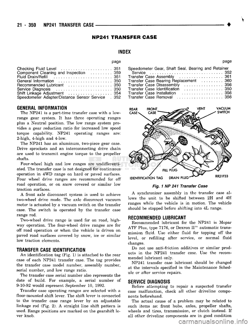
An identification tag (Fig, 1) is attached to the rear
case of each NP241 transfer case. The tag provides
the transfer case model number, assembly number, serial number, and low range ratio. The transfer case serial number also represents the
date of build. For example, a serial number of 9-10-92 would represent September 10, 1992. Transfer case operating ranges are selected with a
floor-mounted shift lever. The shift lever is connected
to the transfer case range lever by an adjustable linkage rod (Fig. 2). A straight line shift pattern is
used. Range positions are marked on the gearshift le
ver knob.
Fig.
1 NP 241 Transfer
Case
A synchronizer assembly in the transfer case al
lows the unit to be shifted between 2H and 4H
ranges while the vehicle is in motion. The vehicle should be stopped before shifting into 4L range.
RECOMMENDED
LUBRICANT
Recommended lubricant for the NP241 is Mopar
ATF Plus, type 7176, or Dexron II™ automatic trans
mission fluid. Use either fluid for topping off the
level, or refilling after service, or normal fluid
changes. Do not use anti-friction additives or similar prod
ucts in the NP241 transfer case. Use the recom
mended lubricant only. NP241 transfer case lubricant should be changed
at the intervals specified in the Maintenance Sched
ule or after service repairs.
SERVICE
DIAGNOSIS
Before attempting to repair a suspected transfer
case malfunction, check all other driveline compo
nents beforehand. The actual cause of a problem may be related to
such items as: front hubs, axles, propeller shafts,
wheels and tires, transmission, or clutch instead. If all other driveline components are in good condition
Page 1373 of 1502

22 - 4
WHEELS
AND
TIRES
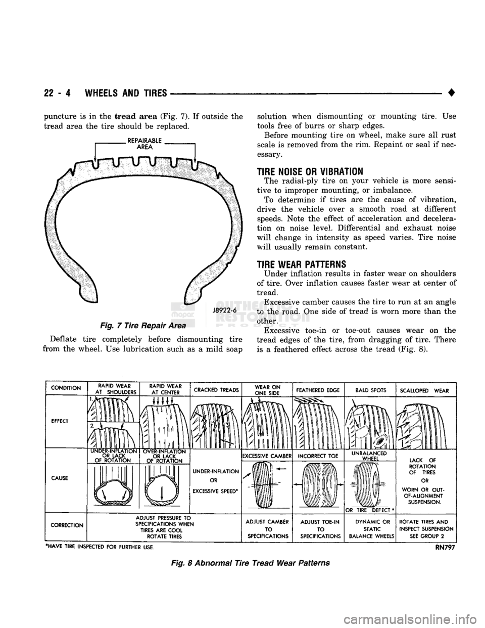
• puncture is in the tread area (Fig. 7). If outside the
tread area the tire should be replaced.
J8922-6
Fig.
7
Tire
Repair Area
Deflate tire completely before dismounting tire
from the wheel. Use lubrication such as a mild soap solution when dismounting or mounting tire. Use
tools free of burrs or sharp edges.
Before mounting tire on wheel, make sure all rust
scale is removed from the rim. Repaint or seal if nec
essary.
TIRE NOISE
OR
VIBRATION
The radial-ply tire on your vehicle is more sensi
tive to improper mounting, or imbalance. To determine if tires are the cause of vibration,
drive the vehicle over a smooth road at different speeds. Note the effect of acceleration and decelera
tion on noise level. Differential and exhaust noise
will change in intensity as speed varies. Tire noise
will usually remain constant.
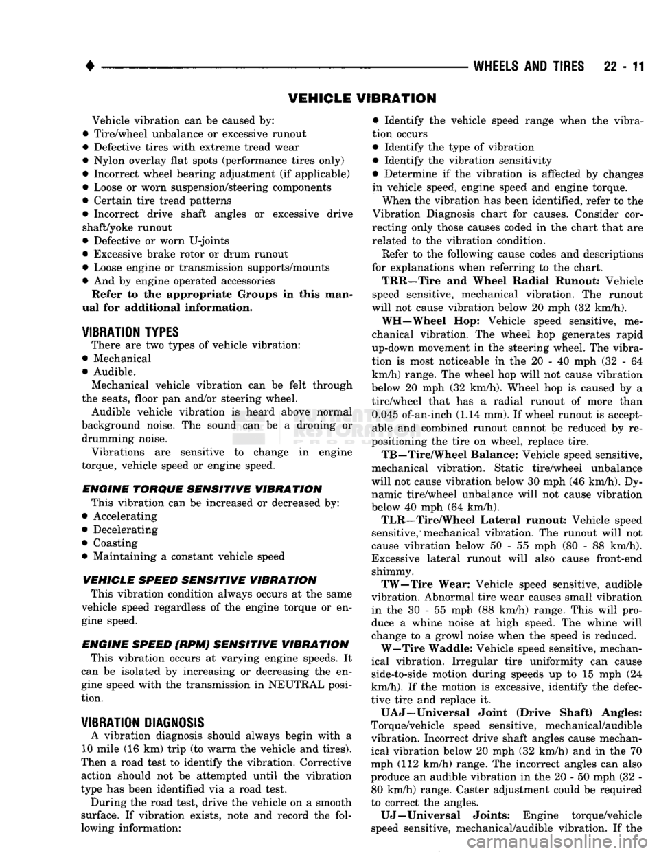
TIRE WEAR PATTERNS
Under inflation results in faster wear on shoulders
of tire. Over inflation causes faster wear at center of
tread. Excessive camber causes the tire to run at an angle
to the road. One side of tread is worn more than the other. Excessive toe-in or toe-out causes wear on the
tread edges of the tire, from dragging of tire. There is a feathered effect across the tread (Fig. 8).
CRACKED
TREADS
WEAR
ON
ONE SIDE FEATHERED EDGE
BALD
SPOTS
IP
fa
SCALLOPED
WEAR
EXCESSIVE
CAMBER INCORRECT
TOE
EXCESSIVE
SPEED*
UNBALANCED
WHEEL LACK
OF
ROTATION
OF TIRES
OR
WORN
OR OUT-
OF-ALIGNMENT
SUSPENSION.
OR
TIRE
DEFECT* ADJUST
PRESSURE
TO
SPECIFICATIONS
WHEN
TIRES ARE COOL
ROTATE
TIRES ADJUST CAMBER
TO
SPECIFICATIONS ADJUST
TOE-IN
TO
SPECIFICATIONS DYNAMIC
OR
STATIC
BALANCE
WHEELS
ROTATE
TIRES
AND
INSPECT SUSPENSION
SEE
GROUP
2
•HAVE
TIRE
INSPECTED
FOR
FURTHER
USE.
RN797
Fig.
8 Abnormal Tire Tread Wear Patterns
Page 1380 of 1502

•
WHEELS
AND
TIRES
22-11 VEHICLE VIBRATION
Vehicle vibration can
be
caused by:
• Tire/wheel unbalance
or
excessive runout
• Defective tires with extreme tread wear
• Nylon overlay flat spots (performance tires only)
• Incorrect wheel bearing adjustment
(if
applicable)
• Loose
or
worn suspension/steering components
• Certain tire tread patterns
• Incorrect drive shaft angles
or
excessive drive
shaft/yoke runout
• Defective
or
worn U-joints
• Excessive brake rotor
or
drum runout
• Loose engine
or
transmission supports/mounts
• And
by
engine operated accessories Refer
to the
appropriate Groups
in
this man
ual for additional information.
VIBRATION
TYPES
There are two types
of
vehicle vibration:
• Mechanical
• Audible. Mechanical vehicle vibration
can be
felt through
the seats, floor pan and/or steering wheel. Audible vehicle vibration
is
heard above normal
background noise.
The
sound
can be a
droning
or
drumming noise. Vibrations
are
sensitive
to
change
in
engine
torque, vehicle speed
or
engine speed.
ENGINE TORQUE SENSITIVE VIBRATION
This vibration can
be
increased
or
decreased by:
• Accelerating
• Decelerating
• Coasting
• Maintaining
a
constant vehicle speed
VEHICLE SPEED SENSITIVE VIBRATION
This vibration condition always occurs
at
the same
vehicle speed regardless
of
the engine torque
or en
gine speed.
ENGINE SPEED
{RPM}
SENSITIVE VIBRATION
This vibration occurs
at
varying engine speeds.
It
can
be
isolated
by
increasing
or
decreasing
the en
gine speed with the transmission
in
NEUTRAL posi
tion.
VIBRATION
DIAGNOSIS
A vibration diagnosis should always begin with
a
10 mile (16 km) trip (to warm the vehicle and tires).
Then
a
road test
to
identify the vibration. Corrective action should
not be
attempted until
the
vibration
type has been identified
via a
road test. During the road test, drive the vehicle
on a
smooth
surface.
If
vibration exists, note
and
record
the
fol
lowing information: • Identify
the
vehicle speed range when
the
vibra
tion occurs
• Identify the type
of
vibration
• Identify the vibration sensitivity
• Determine
if
the vibration
is
affected
by
changes
in vehicle speed, engine speed and engine torque. When the vibration has been identified, refer to the
Vibration Diagnosis chart
for
causes. Consider cor
recting only those causes coded
in
the chart that
are
related
to
the vibration condition.
Refer
to
the following cause codes and descriptions
for explanations when referring
to
the chart.
TRR—Tire
and
Wheel Radial Runout: Vehicle
speed sensitive, mechanical vibration.
The
runout
will not cause vibration below
20
mph (32 km/h).
WH—Wheel Hop: Vehicle speed sensitive,
me
chanical vibration.
The
wheel
hop
generates rapid
up-down movement
in
the steering wheel. The vibra
tion
is
most noticeable
in the 20 - 40
mph
(32 - 64
km/h) range. The wheel hop will not cause vibration
below
20
mph (32 km/h). Wheel hop
is
caused
by a
tire/wheel that
has a
radial runout
of
more than 0.045 of-an-inch (1.14 mm).
If
wheel runout
is
accept
able
and
combined runout cannot
be
reduced
by re
positioning the tire
on
wheel, replace tire.
TB—Tire/Wheel Balance: Vehicle speed sensitive,
mechanical vibration. Static tire/wheel unbalance
will not cause vibration below 30 mph (46 km/h). Dy
namic tire/wheel unbalance will
not
cause vibration
below
40
mph (64 km/h). TLR—Tire/Wheel Lateral runout: Vehicle speed
sensitive, mechanical vibration. The runout will
not
cause vibration below
50 - 55 mph (80 - 88
km/h).
Excessive lateral runout will also cause front-end shimmy. TW—Tire Wear: Vehicle speed sensitive, audible
vibration. Abnormal tire wear causes small vibration in
the 30 - 55
mph
(88
km/h) range. This will pro
duce
a
whine noise
at
high speed.
The
whine will
change
to a
growl noise when the speed
is
reduced. W—Tire Waddle: Vehicle speed sensitive, mechan
ical vibration. Irregular tire uniformity
can
cause
side-to-side motion during speeds
up to 15
mph
(24
km/h).
If
the motion
is
excessive, identify
the
defec
tive tire and replace
it.
U A J—Universal Joint (Drive Shaft) Angles:
Torque/vehicle speed sensitive, mechanical/audible
vibration. Incorrect drive shaft angles cause mechan ical vibration below
20
mph (32 km/h) and
in
the
70
mph (112 km/h) range. The incorrect angles can also
produce
an
audible vibration
in
the 20
-
50 mph (32
-
80 km/h) range. Caster adjustment could
be
required
to correct the angles. UJ—Universal Joints: Engine torque/vehicle
speed sensitive, mechanical/audible vibration.
If
the
Page 1489 of 1502

25
- 12
EMISSION
CONTROL
SYSTEMS
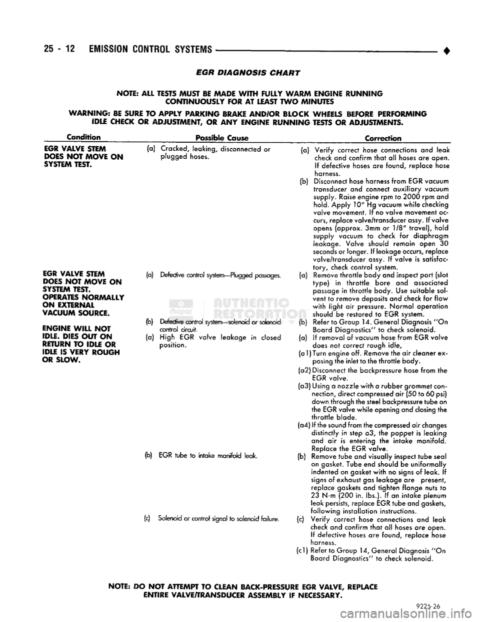
EGR
DIAGNOSIS
CHART
NOTE: ALL TESTS MUST BE MADE
WITH
FULLY
WARM ENGINE RUNNING CONTINUOUSLY FOR
AT
LEAST TWO MINUTES
WARNING: BE SURE
TO
APPLY PARKING BRAKE AND/OR BLOCK WHEELS BEFORE PERFORMING IDLE CHECK
OR
ADJUSTMENT,
OR ANY
ENGINE RUNNING TESTS
OR
ADJUSTMENTS.
Condition
Possible Cause
Correction
EGR
VALVE STEM
DOES
NOT MOVE
ON
SYSTEM
TEST.
(a) Cracked, leaking, disconnected or
plugged hoses.
EGR
VALVE STEM
DOES
NOT MOVE
ON
SYSTEM
TEST.
OPERATES
NORMALLY
ON EXTERNAL
VACUUM
SOURCE.
ENGINE
WILL
NOT
IDLE.
DIES OUT
ON
RETURN
TO
IDLE
OR
IDLE
IS
VERY ROUGH
OR SLOW.
(a) Defective control system—Plugged passages.
(b) Defective control system—solenoid or solenoid control circuit,
(a) High EGR valve leakage in closed
position.
(b) EGR tube to intake manifold leak.
(c) Solenoid or control signal to solenoid failure. (a)
(b)
(a)
(b)
(a) Verify correct hose connections and leak
check and confirm that alt hoses are open.
If defective hoses are found, replace hose
harness.
Disconnect hose harness from EGR vacuum
transducer and connect auxiliary vacuum supply. Raise engine rpm to 2000 rpm and hold. Apply 10" Hg vacuum while checking
valve movement. If no valve movement oc
curs,
replace valve/transducer assy. If valve
opens (approx. 3mm or 1/8" travel), hold
supply vacuum to check for diaphragm
leakage. Valve should remain open 30
seconds or longer. If leakage occurs, replace
valve/transducer assy. If valve is satisfac
tory, check control system. Remove throttle body and inspect port (slot
type) in throttle bore and associated passage in throttle body. Use suitable sol
vent to remove deposits and check for flow
with light air pressure. Normal operation
should be restored to EGR system. Refer to Group 14. General Diagnosis "On
Board Diagnostics" to check solenoid.
If removal of vacuum hose from EGR valve
does not correct rough idle,
(a
1)
Turn
engine off. Remove the air cleaner ex posing the inlet to the throttle body.
(a2) Disconnect the backpressure hose from the EGR valve.
(a3) Using a nozzle with a rubber grommet con nection, direct compressed air (50 to 60 psi)
down through the steel backpressure tube on
the EGR valve while opening and closing the
throttle blade.
(a4) If the sound from the compressed air changes distinctly in step a3, the poppet is leaking
and air is entering the intake manifold. Replace the EGR valve.
Remove tube and visually inspect tube seal
on gasket. Tube end should be uniformally
indented on gasket with no signs of leak. If
signs of exhaust gas leakage are present, replace gaskets and tighten flange nuts to
23 N-m (200 in. lbs.). If an intake plenum
leak persists, replace EGR tube and gaskets,
following installation instructions.
Verify correct hose connections and leak
check and confirm that all hoses are open. If defective hoses are found, replace nose
harness.
(cl) Refer to Group 14, General Diagnosis "On Board Diagnostics" to check solenoid. (b)
(c)
NOTE:
DO
NOT
ATTEMPT
TO CLEAN BACK-PRESSURE EGR VALVE, REPLACE
ENTIRE VALVE/TRANSDUCER ASSEMBLY
IF
NECESSARY.
9225-26