1993 DODGE TRUCK Bearing nut torque
[x] Cancel search: Bearing nut torquePage 84 of 1502
•
FRONT SUSPENSION
AND
AXLE
2 - 31
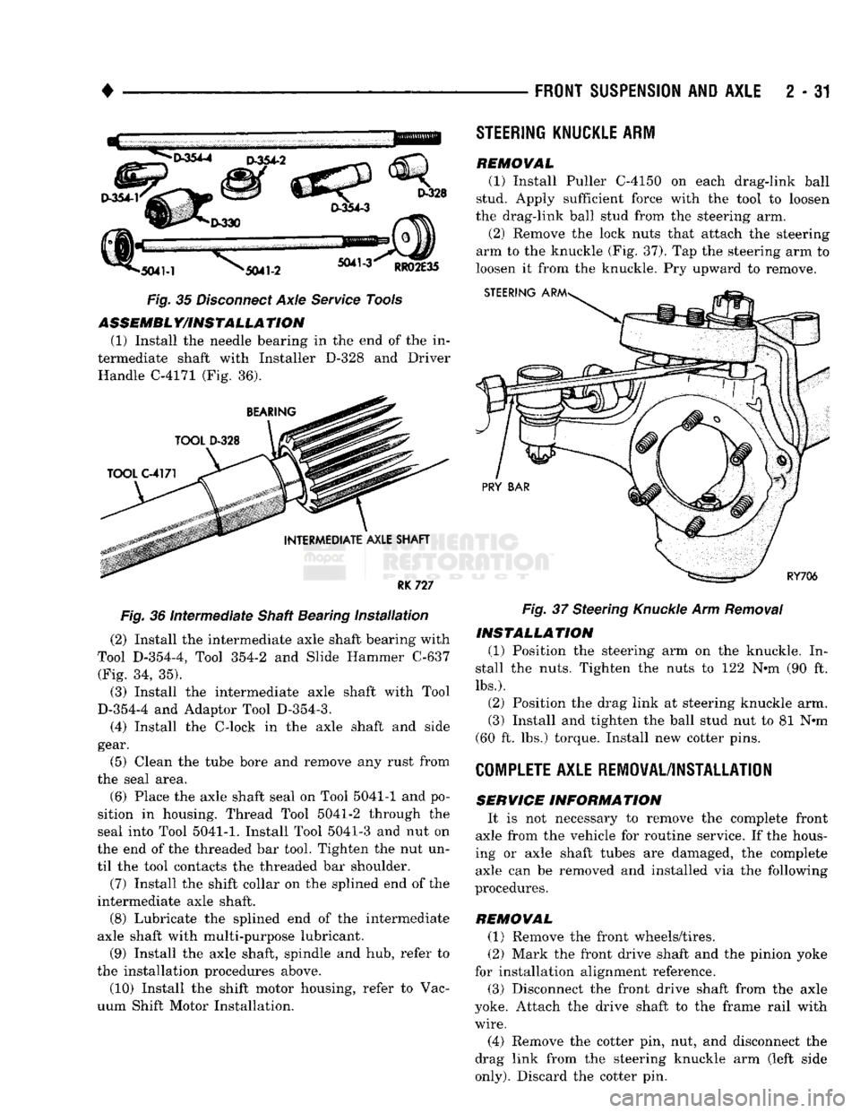
Fig. 35 Disconnect Axle Service Tools ASSEMBLY/INSTALLATION
(1) Install the needle bearing in the end of the in
termediate shaft with Installer D-328 and Driver Handle C-4171 (Fig. 36).
RK
727
Fig. 36 Intermediate Shaft Bearing installation (2) Install the intermediate axle shaft bearing with
Tool D-354-4, Tool 354-2 and Slide Hammer C-637 (Fig. 34, 35).
(3) Install the intermediate axle shaft with Tool
D-354-4 and Adaptor Tool D-354-3.
(4) Install the C-lock in the axle shaft and side
gear.
(5) Clean the tube bore and remove any rust from
the seal area.
(6) Place the axle shaft seal on Tool 5041-1 and po
sition in housing. Thread Tool 5041-2 through the
seal into Tool
5041-1.
Install Tool 5041-3 and nut on
the end of the threaded bar tool. Tighten the nut un
til the tool contacts the threaded bar shoulder.
(7) Install the shift collar on the splined end of the
intermediate axle shaft.
(8) Lubricate the splined end of the intermediate
axle shaft with multi-purpose lubricant.
(9) Install the axle shaft, spindle and hub, refer to
the installation procedures above. (10) Install the shift motor housing, refer to Vac
uum Shift Motor Installation.
STEERING
KNUCKLE
ARM
REMOVAL
(1) Install Puller C-4150 on each drag-link ball
stud. Apply sufficient force with the tool to loosen
the drag-link ball stud from the steering arm.
(2) Remove the lock nuts that attach the steering
arm to the knuckle (Fig. 37). Tap the steering arm to
loosen it from the knuckle. Pry upward to remove. Fig. 37 Steering Knuckle Arm Removal
INSTALLATION
(1) Position the steering arm on the knuckle. In
stall the nuts. Tighten the nuts to 122 N«m (90 ft.
lbs.).
(2) Position the drag link at steering knuckle arm.
(3) Install and tighten the ball stud nut to 81 N*m
(60 ft. lbs.) torque. Install new cotter pins.
COMPLETE
AXLE REMOVAL/INSTALLATION
SERVICE
INFORMATION
It is not necessary to remove the complete front
axle from the vehicle for routine service. If the hous
ing or axle shaft tubes are damaged, the complete axle can be removed and installed via the following
procedures.
REMOVAL (1) Remove the front wheels/tires.
(2) Mark the front drive shaft and the pinion yoke
for installation alignment reference.
(3) Disconnect the front drive shaft from the axle
yoke. Attach the drive shaft to the frame rail with
wire.
(4) Remove the cotter pin, nut, and disconnect the
drag link from the steering knuckle arm (left side
only).
Discard the cotter pin.
Page 85 of 1502
2
- 32
FRONT
SUSPENSION
AND
AXLE
• (5) Disconnect flexible brake fluid hose fittings at
the frame crossmember. Plug the hoses at the fit
tings.
(6) Remove the shock absorber lower nut and stud
from the axle shaft tube bracket. Remove the nuts and disconnect the stabilizer bar links from the
spring brackets.
(7) Disconnect the vacuum hoses and wiring con
nections from the shift motor housing.
(8) Remove nuts and the washers from the spring
U-bolts. Remove the complete front axle from the ve
hicle.
INSTALLATION
(1) Position the front axle under the front of the
vehicle with the axle spring pads under the springs.
Place the spring brackets over the springs. Make sure the stabilizer bar link bolt holes face toward the
rear of the vehicle.
(2) Install the spring U-bolts, washers and nuts.
Refer to Front Suspension — 4WD Vehicles within
this group. (3) Install the shock absorber. Refer to Front Sus
pension — 4WD Vehicles within this group. (4) Connect the stabilizer bar links to the spring
brackets. Refer to Front Suspension-4WD Vehicles
within this group.
(5) Remove plugs and connect the brake hose fit
tings.
Refer to Group 5, Brakes. (6) Connect the drag-link ball stud to the steering
knuckle arm. Refer to Group 19, Steering. (7) Connect the drive shaft to the pinion yoke with
the installation reference marks aligned. Install the
washers and the nuts and tighten to 19 N*m (14 ft. lbs.) torque.
(8) Connect the vacuum hoses and wiring connec
tions to the shift motor housing. (9) Remove the supports, lower the vehicle and re
move the block from the brake pedal.
(10) Raise the vehicle.
• Bleed and adjust the brakes
• Lubricate all the ball stud fittings
• Inspect the differential housing lubricant level. Re
fer to Group 0, Lubrication and Maintenance. (11) Lower the vehicle and test the axle and sus
pension operation.
DIFFERENTIAL
DISASSEMBLY
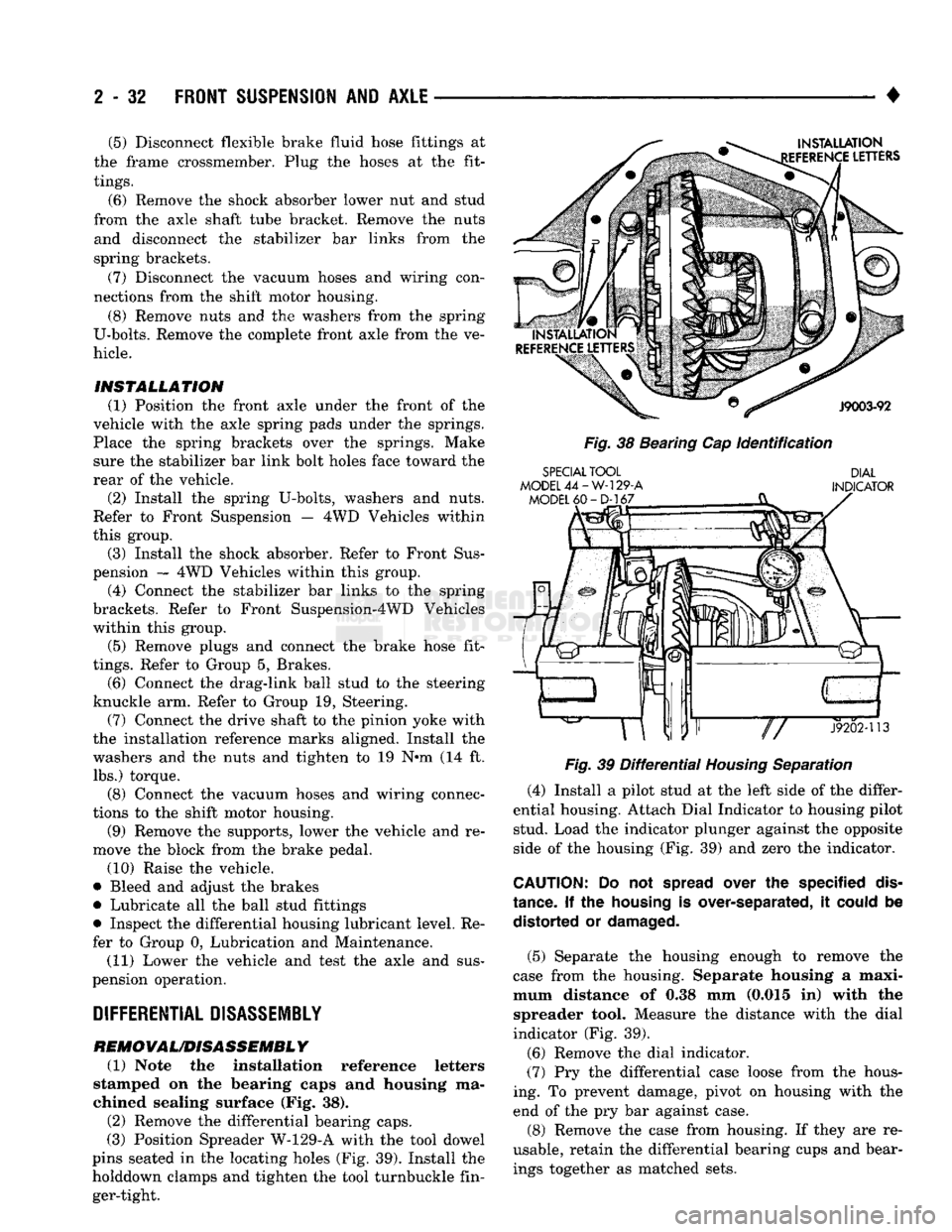
REMOVAL/DISASSEMBLY (1) Note the installation reference letters
stamped on the bearing caps and housing ma
chined sealing surface (Fig. 38). (2) Remove the differential bearing caps.
(3) Position Spreader W-129-A with the tool dowel
pins seated in the locating holes (Fig. 39). Install the
holddown clamps and tighten the tool turnbuckle fin ger-tight.
INSTALLATION
EFERENCE
LETTERS
J9003-92
Fig.
38 Bearing Cap
Identification
SPECIAL
TOOL
MODEL
44-W-129-A
MODEL
60-D-167
DIAL
INDICATOR
«ar"P—
J9202-113
Fig.
39
Differential
Housing
Separation
(4) Install a pilot stud at the left side of the differ
ential housing. Attach Dial Indicator to housing pilot stud. Load the indicator plunger against the opposite
side of the housing (Fig. 39) and zero the indicator.
CAUTION:
Do not
spread
over the specified
dis
tance.
If the
housing
is over-separated, it
could
be distorted or
damaged.
(5) Separate the housing enough to remove the
case from the housing. Separate housing a maxi
mum distance of 0.38 mm (0.015 in) with the spreader tool. Measure the distance with the dial
indicator (Fig. 39).
(6) Remove the dial indicator.
(7) Pry the differential case loose from the hous
ing. To prevent damage, pivot on housing with the end of the pry bar against case.
(8) Remove the case from housing. If they are re
usable, retain the differential bearing cups and bear ings together as matched sets.
Page 92 of 1502
•
FRONT
SUSPENSION
AND
AXLE
2 - 39
Fig.
59
Pinion
Height
Block
Against
Arbor
Fig.
60
Pinion
Gear Depth Measurement
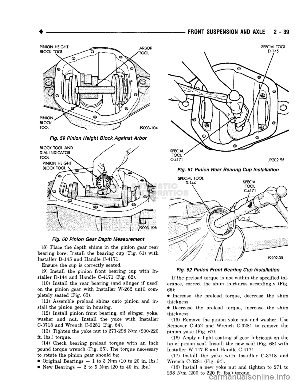
(8) Place the depth shims in the pinion gear rear
bearing bore. Install the bearing cup (Fig. 61) with Installer D-145 and Handle C-4171.
Ensure the cup is correctly seated. (9) Install the pinion front bearing cup with In
staller D-144 and Handle C-4171 (Fig. 62).
(10) Install the rear bearing (and slinger if used)
on the pinion gear with Installer W-262 until com
pletely seated (Fig. 63).
(11) Assemble preload shims onto pinion and in
stall the pinion gear in housing.
(12) Install pinion front bearing, oil slinger, yoke,
washer and nut. Install the yoke with Installer C-3718 and Wrench C-3281 (Fig. 64).
(13) Tighten the yoke nut to 271-298 N-m (200-220
ft. lbs.) torque. (14) Check bearing preload torque with an inch
pound torque wrench (Fig. 65). The torque necessary
to rotate the pinion gear should be;
• Original Bearings — 1 to 3 N*m (10 to 20 in. lbs.)
• New Bearings — 2 to 5 N*m (20 to 40 in. lbs.)
SPECIAL
TOOL
C-4171
J9202-95
Fig.
61
Pinion
Rear Bearing Cup
Installation
SPECIAL
TOOL
D-144
SPECIAL Fig.
62
Pinion
Front Bearing Cup
Installation
If the preload torque is not within the specified tol
erance, correct the shim thickness accordingly (Fig.
66);
• Increase the preload torque, decrease the shim
thickness
• Decrease the preload torque, increase the shim
thickness
(15) Remove the pinion yoke nut and washer. Use
Remover C-452 and Wrench C-3281 to remove the
pinion yoke (Fig. 67).
(16) Apply a light coating of gear lubricant on the
lip of pinion seal. Install the new seal (Fig. 68) with
Installer W-147-E and Handle C-4171
(17) Install the yoke with Installer C-3718 and
Wrench C-3281 (Fig. 64). (18) Install a new yoke nut and tighten to 271 to
298 N-m (200 to 220 ft. lbs.) torque.
Page 94 of 1502
•
FRONT
SUSPENSION
AND
AXLE
2 - 41
SPECIAL
TOOL
D-145
Fig.
67
Pinion
Yoke
Removal
HANDLE
C-4171
SPECIAL
TOOL
C-4171
J9202-95 Fig.
69
Pinion
Rear Bearing Cup
Installation
SPECIAL
TOOL
D-144
SPECIAL
TOOL
C-4171
SPECIAL
TOOL
W-147-E
(J25104)
J9202-19
Fig.
68
Pinion
Seal
Installation
the separation distance. The required thickness
of the depth shim(s) is determined according to
the following information.
(4) Loosen the compression nut tool. Lubricate the
pinion gear front and rear bearings with gear lubri cant. Re-tighten the compression nut tool to 1 to 3
N«m (15 to 25 in. lbs.) torque. Rotate the pinion gear
several complete revolutions to align the bearing
rollers.
(5) Install Gauge Block SP-5260 at the end of SP-
526.
Install Cap Screw (SP-536) and tighten with
Wrench
SP-531.
(6) Position Crossbore Arbor (SP-5183) in the
dif
ferential housing.
J9202-35
Fig.
70
Pinion
Front Bearing Cup
Installation
Center the arbor in cradles so equal space exists at
both ends. Position the bearing caps on the arbor
tool. Install the bolts. Tighten the cap bolts to 14 N*m (10 ft. lbs.) torque.
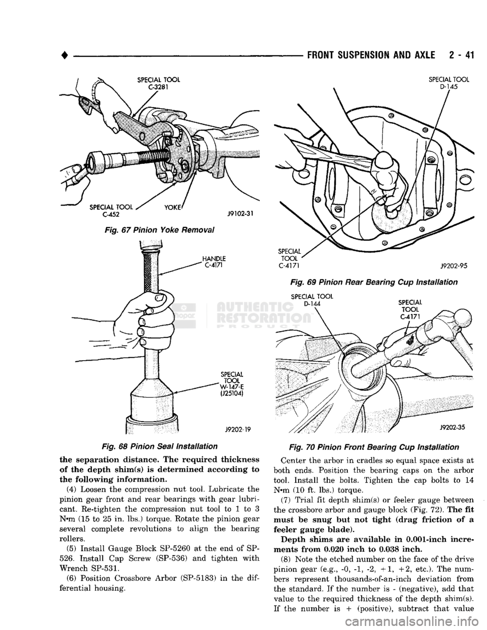
(7) Trial fit depth shim(s) or feeler gauge between
the crossbore arbor and gauge block (Fig. 72). The fit must be snug but not tight (drag friction of a
feeler gauge blade).
Depth shims are available in 0.001-inch incre
ments from 0.020 inch to 0.038 inch.
(8) Note the etched number on the face of the drive
pinion gear (e.g., -0, -1, -2, +1, +2, etc.). The num
bers represent thousands-of-an-inch deviation from
the standard. If the number is - (negative), add that value to the required thickness of the depth shim(s).
If the number is + (positive), subtract that value
Page 95 of 1502
2
- 42
FRONT
SUSPENSION
AND
AXLE
DIFFERENTIAL HOUSING HAMMER
DRIVER
HANDLE
YOKE
HOLDING TOOL
C-3281
Fig.
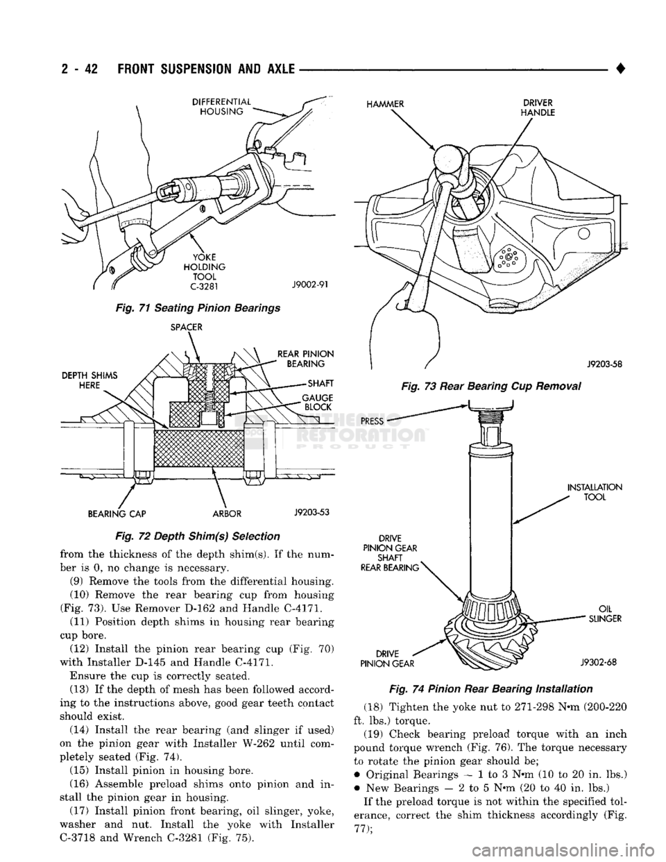
71 Seating Pinion Bearings SPACER
J9002-91
DEPTH
SHIMS
HERE
REAR
PINION
BEARING
SHAFT
BEARING
CAP ARBOR
J9203-53
Fig.
72 Depth Shim(s) Selection from the thickness of the depth shim(s). If the num
ber is 0, no change is necessary.
(9) Remove the tools from the differential housing.
(10) Remove the rear bearing cup from housing
(Fig. 73). Use Remover D-162 and Handle C-4171. (11) Position depth shims in housing rear bearing
cup bore.
(12) Install the pinion rear bearing cup (Fig. 70)
with Installer D-145 and Handle C-4171.
Ensure the cup is correctly seated. (13) If the depth of mesh has been followed accord
ing to the instructions above, good gear teeth contact
should exist.
(14) Install the rear bearing (and slinger if used)
on the pinion gear with Installer W-262 until com
pletely seated (Fig. 74).
(15) Install pinion in housing bore.
(16) Assemble preload shims onto pinion and in
stall the pinion gear in housing. (17) Install pinion front bearing, oil slinger, yoke,
washer and nut. Install the yoke with Installer C-3718 and Wrench C-3281 (Fig. 75).
J9203-58
Fig.
73 Rear Bearing Cup
Removal
PRESS
•
DRIVE
PINION
GEAR
SHAFT
REAR BEARING
^
INSTALLATION
TOOL
DRIVE
PINION
GEAR
OIL
SUNGER
J9302-68
Fig.
74
Pinion
Rear Bearing
Installation
(18) Tighten the yoke nut to 271-298 N-m (200-220
ft. lbs.) torque.
(19) Check bearing preload torque with an inch
pound torque wrench (Fig. 76). The torque necessary to rotate the pinion gear should be;
• Original Bearings — 1 to 3 N-m (10 to 20 in. lbs.)
• New Bearings — 2 to 5 N-m (20 to 40 in. lbs.) If the preload torque is not within the specified tol
erance, correct the shim thickness accordingly (Fig.
77);
Page 96 of 1502
FRONT SUSPENSION
AND
AXLE
2 43
SPECIAL
DIFFERENTIAL
TOOL
HOUSING J9103-21
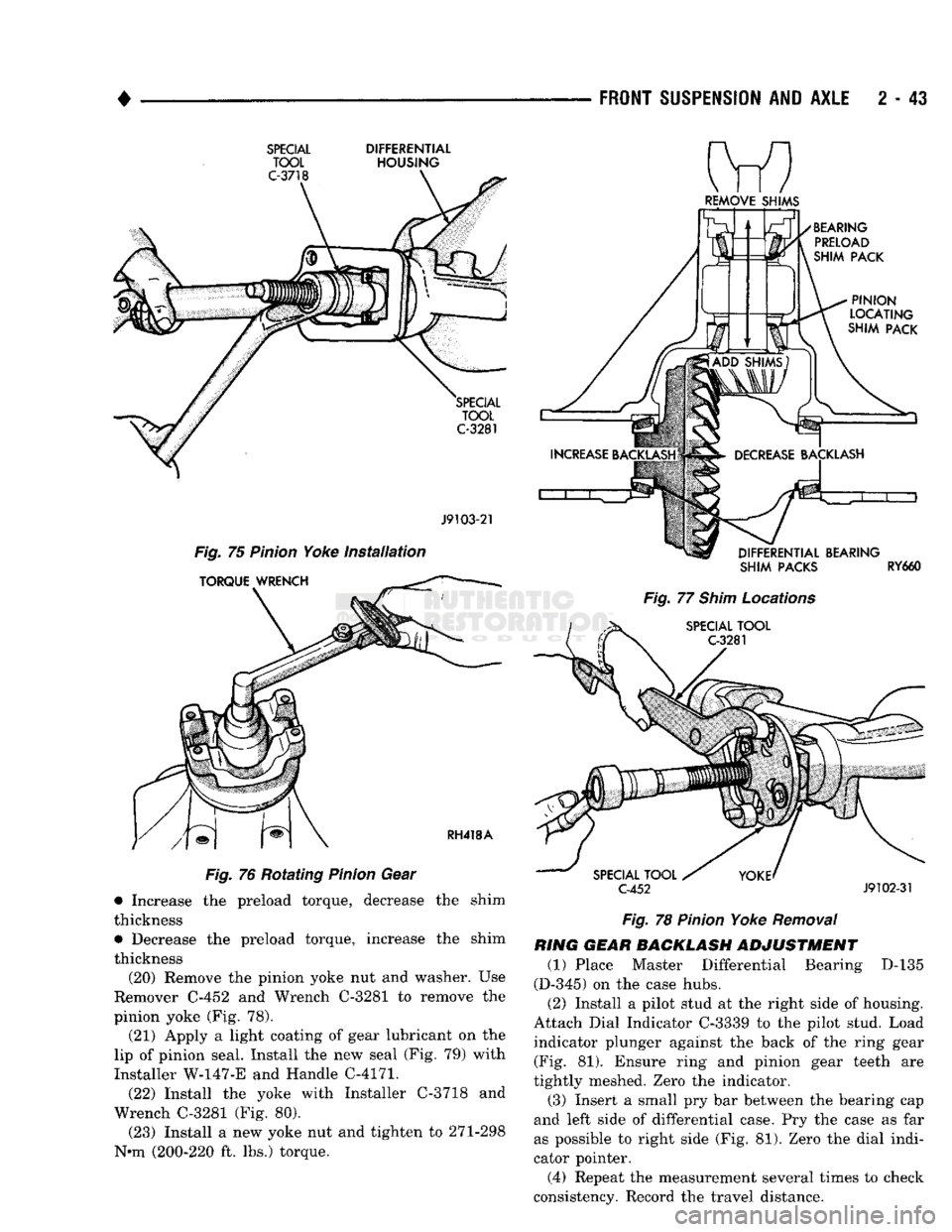
Fig. 75 Pinion Yoke Installation
Fig. 76 Rotating Pinion Gear • Increase the preload torque, decrease the shim
thickness • Decrease the preload torque, increase the shim
thickness
(20) Remove the pinion yoke nut and washer. Use
Remover C-452 and Wrench C-3281 to remove the
pinion yoke (Fig. 78).
(21) Apply a light coating of gear lubricant on the
lip of pinion seal. Install the new seal (Fig. 79) with
Installer
W-147-E
and Handle C-4171.
(22) Install the yoke with Installer C-3718 and
Wrench C-3281 (Fig. 80).
(23) Install a new yoke nut and tighten to 271-298
N*m (200-220 ft. lbs.) torque.
REMOVE
SHIMS
SHIM
PACKS
RY660
Fig. 77 Shim Locations
C-452
J9102-31
Fig. 78 Pinion Yoke Removal
RING
GEAR BACKLASH
ADJUSTMENT
(1) Place Master Differential Bearing D-135
(D-345) on the case hubs.
(2) Install a pilot stud at the right side of housing.
Attach Dial Indicator C-3339 to the pilot stud. Load indicator plunger against the back of the ring gear (Fig. 81). Ensure ring and pinion gear teeth are
tightly meshed. Zero the indicator.
(3) Insert a small pry bar between the bearing cap
and left side of differential case. Pry the case as far
as possible to right side (Fig. 81). Zero the dial indi
cator pointer.
(4) Repeat the measurement several times to check
consistency. Record the travel distance.
Page 107 of 1502
2
- 54
FRONT SUSPENSION
AND
AXLE
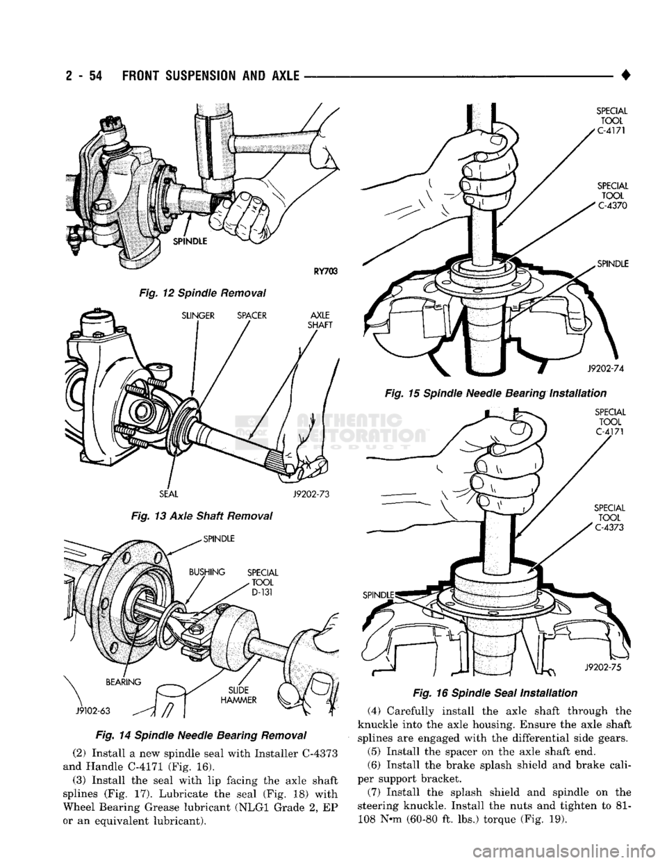
Fig.
12 Spindle Removal
SEAL
J9202-73
Fig.
13 Axle Shaft Removal
Fig.
14
Spindle
Needle Bearing
Removal
(2) Install a new spindle seal with Installer C-4373
and Handle C-4171 (Fig. 16).
(3) Install the seal with lip facing the axle shaft
splines (Fig. 17). Lubricate the seal (Fig. 18) with
Wheel Bearing Grease lubricant (NLGI Grade 2, EP
or an equivalent lubricant). •
Fig.
15
Spindle
Needle Bearing
Installation
Fig.
16
Spindle
Seal
Installation
(4) Carefully install the axle shaft through the
knuckle into the axle housing. Ensure the axle shaft splines are engaged with the differential side gears.
(5) Install the spacer on the axle shaft end.
(6) Install the brake splash shield and brake cali
per support bracket.
(7) Install the splash shield and spindle on the
steering knuckle. Install the nuts and tighten to 81- 108 N-m (60-80 ft. lbs.) torque (Fig. 19).
Page 108 of 1502
•
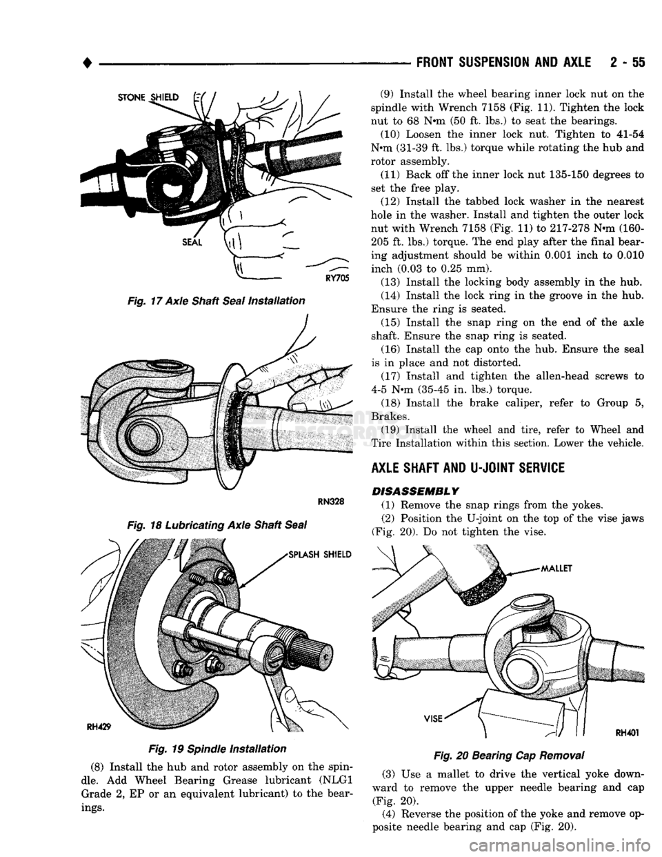
Fig.
17 Axle Shaft
Seal
Installation
Fig.
19
Spindle
Installation
(8) Install the hub and rotor assembly on the spin
dle.
Add Wheel Bearing Grease lubricant (NLGI Grade 2, EP or an equivalent lubricant) to the bear
ings.
FRONT
SUSPENSION
AND
AXLE
2 - 51
Fig.
20 Bearing Cap
Removal
(3) Use a mallet to drive the vertical yoke down
ward to remove the upper needle bearing and cap (Fig. 20).
(4) Reverse the position of the yoke and remove op
posite needle bearing and cap (Fig. 20). (9) Install the wheel bearing inner lock nut on the
spindle with Wrench 7158 (Fig. 11). Tighten the lock
nut to 68 N*m (50 ft. lbs.) to seat the bearings. (10) Loosen the inner lock nut. Tighten to 41-54
N*m (31-39 ft. lbs.) torque while rotating the hub and
rotor assembly.
(11) Back off the inner lock nut 135-150 degrees to
set the free play.
(12) Install the tabbed lock washer in the nearest
hole in the washer. Install and tighten the outer lock nut with Wrench 7158 (Fig. 11) to 217-278 N-m (160-205 ft. lbs.) torque. The end play after the final bear
ing adjustment should be within 0.001 inch to 0.010 inch (0.03 to 0.25 mm).
(13) Install the locking body assembly in the hub.
(14) Install the lock ring in the groove in the hub.
Ensure the ring is seated. (15) Install the snap ring on the end of the axle
shaft. Ensure the snap ring is seated.
(16) Install the cap onto the hub. Ensure the seal
is in place and not distorted.
(17) Install and tighten the allen-head screws to
4-5 N-m (35-45 in. lbs.) torque.
(18) Install the brake caliper, refer to Group 5,
Brakes. (19) Install the wheel and tire, refer to Wheel and
Tire Installation within this section. Lower the vehicle.
AXLE SHAFT AND
U-JOINT
SERVICE DISASSEMBLY
(1) Remove the snap rings from the yokes.
(2) Position the U-joint on the top of the vise jaws
(Fig. 20). Do not tighten the vise.