1993 DODGE TRUCK Bearing nut torque
[x] Cancel search: Bearing nut torquePage 150 of 1502
•
REAR SUSPENSION
AND
AXLE
3 - 23
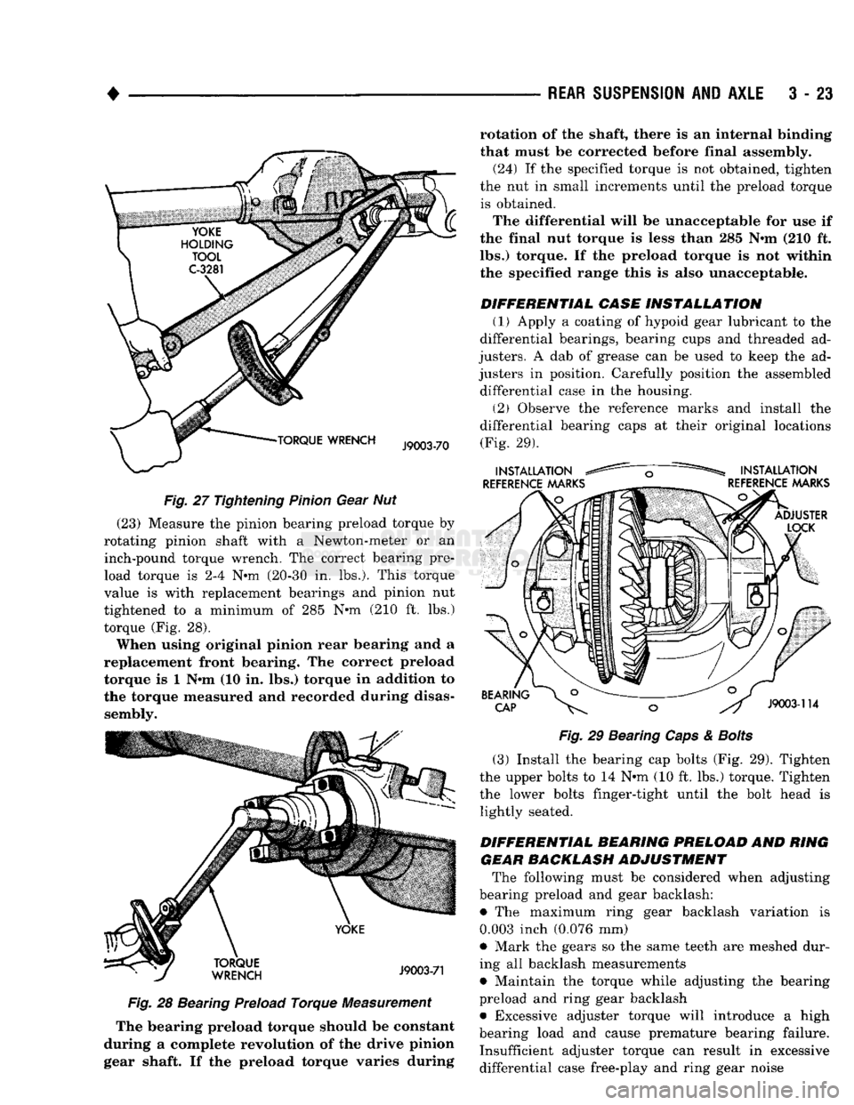
Fig. 27 Tightening Pinion Gear Nut (23) Measure the pinion bearing preload torque by
rotating pinion shaft with a Newton-meter or an inch-pound torque wrench. The correct bearing preload torque is 2-4 N-m (20-30 in. lbs.). This torque
value is with replacement bearings and pinion nut
tightened to a minimum of 285 N-m (210 ft. lbs.)
torque (Fig. 28).
When using original pinion rear bearing and a
replacement front bearing. The correct preload torque is 1 N-m (10 in. lbs.) torque in addition to
the torque measured and recorded during disas sembly. Fig. 28 Bearing Preload Torque Measurement
The bearing preload torque should be constant
during a complete revolution of the drive pinion
gear shaft. If the preload torque varies during rotation of the shaft, there is an internal binding
that must be corrected before final assembly.
(24) If the specified torque is not obtained, tighten
the nut in small increments until the preload torque is obtained.
The differential will be unacceptable for use if
the final nut torque is less than 285 N-m (210 ft.
lbs.) torque. If the preload torque is not within the specified range this is also unacceptable.
DIFFERENTIAL CASE INSTALLATION (1) Apply a coating of hypoid gear lubricant to the
differential bearings, bearing cups and threaded ad
justers. A dab of grease can be used to keep the ad
justers in position. Carefully position the assembled differential case in the housing.
(2) Observe the reference marks and install the
differential bearing caps at their original locations (Fig. 29).
Fig.
29 Bearing
Caps
&
Bolts
(3) Install the bearing cap bolts (Fig. 29). Tighten
the upper bolts to 14 N-m (10 ft. lbs.) torque. Tighten the lower bolts finger-tight until the bolt head is lightly seated.
DIFFERENTIAL BEARING PRELOAD AND RING GEAR BACKLASH ADJUSTMENT The following must be considered when adjusting
bearing preload and gear backlash:
• The maximum ring gear backlash variation is
0.003 inch (0.076 mm)
• Mark the gears so the same teeth are meshed dur
ing all backlash measurements
• Maintain the torque while adjusting the bearing
preload and ring gear backlash • Excessive adjuster torque will introduce a high
bearing load and cause premature bearing failure. Insufficient adjuster torque can result in excessive differential case free-play and ring gear noise
Page 154 of 1502
•
REAR
SUSPENSION
AND
AXLE
3 - 27
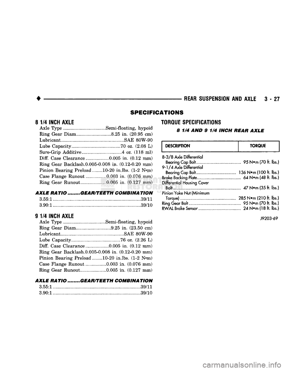
SPECIFICATIONS
8
1/4
INCH AXLE
Axle Type .Semi-floating, hypoid
Ring Gear Diam.. ....8.25
in.
(20.95 cm)
Lubricant............................. .........SAE 80W-90
Lube Capacity.....
70
oz. (2.08
L)
Sure-Grip Additive ....4 oz. (118
ml)
Diff.
Case Clearance.. 0.005
in.
(0.12 mm)
Ring Gear Backlash.0.005-0.008
in.
(0.12-0.20 mm)
Pinion Bearing Preload........ 10-20 in.lbs. (1-2 N*m) Case Flange Runout ................0.003
in.
(0.076 mm)
Ring Gear Runout ....0.005
in.
(0.127 mm)
AXLE
RATIOm„...,„GEAR/TEETH COMBINATION
3.55:1.....
39/11
3.90:1............
...............39/10
9
1/4
INCH AXLE
Axle Type .............Semi-floating, hypoid
Ring Gear Diam 9.25
in.
(23.50 cm)
Lubricant ....................SAE 80W-90
Lube Capacity ........76 oz. (2.26
L)
Diff.
Case Clearance 0.005
in.
(0.12 mm)
Ring Gear Backlash.0.005-0.008
in,
(0.12-0.20 mm)
Pinion Bearing Preload. 10-20 in.lbs. (1-2 Nnn) Case Flange Runout ................0.003
in.
(0.076 mm)
Ring Gear Runout..... .......0.005
in.
(0.127 mm)
AXLE
RATIO ........GEAR/TEETH COMBINATION
3.55:1.
.......39/11
3.90:1..............
39/10
TORQUE SPECIFICATIONS
8
1/4 AND 9 1/4
INCH
REAR AXLE
DESCRIPTION
TORQUE
8-3/8
Axle
Differential
Bearing Cap Bolt
9-1/4
Axle
Differential
Bearing Cap Bolt
Brake Backing
Plate
Differential
Housing
Cover
Bolt....
Pinion Yoke Nut (Minimum
Torque)
Ring
Gear Bolt
RWAL
Brake
Sensor...........
95 N*m (70 ft.
lbs.)
136 N»m(100ft.
lbs.!
... 64
N*m (48 ft. lbs.]
47
N»m
(35 ft.
lbs.)
285 N*m
(21
Oft. lbs.)
... 95
N*m (70 ft. lbs.)
... 24
N*m (18 ft.
lbs.)
J9203-69
Page 160 of 1502
•
REAR
SUSPENSION
AND
AXLE
3 - 33
WHEEL BEARING SERVICE
REMOVAL (1) Remove the axle shaft, refer to the removal
procedure. (2) Remove the nut lock and adjustment nut.
(3) Remove the hub and drum assembly. The outer
wheel bearing will slide out as the hub is being re
moved. (4) Place hub on bench and remove inner grease
seal. Discard seal. (5) Remove inner wheel bearing. Inspect wheel
bearings for wear. Replace as necessary.
CLEANING AND INSPECTION (1) Thoroughly clean both wheel bearings and in
terior of the hub. Remove all of the residual lubri cant. (2) To clean the bearings:
• Soak them in an appropriate cleaning solvent
• Strike the flat of each bearing against a hardwood
block several times • Flush bearing between strikes
• Repeat the procedure above until each bearing is clean
• Dry the bearings with compressed air but do not
spin them (3) After cleaning, apply engine oil to each bear
ing. (4) Rotate each bearing slowly while applying
downward force. Examine the rollers for pitting and
roughness. Replace worn or otherwise defective bear
ings.
If a bearing has pitted and/or rough surfaced
rollers, replace both the bearing and bearing cup. (5) If reusable, remove the engine oil from each
bearing. Pack each bearing with multi-purpose
NLGI, grade 2, EP-type lubricant. Ensure that lubricant is forced into all the cav
ities between the bearing cage and rollers.
INSTALLATION (1) If a bearing and cup must be replaced, remove
the cup from the hub bore. Use a brass drift or an appropriate removal tool to tap out the cup. (2) Install the replacement bearing cup(s) with an
appropriate installation tool.
(3) Apply lubricant to surface area of the hub bore.
Install the inner wheel bearing in the hub. Install a
replacement bearing seal with an appropriate seal installation tool. (4) Inspect the bearing and seal contact surfaces on
the axle for burrs and/or roughness.
(5) Remove all the rough contact surfaces from the
axle.
Apply a coating of multi-purpose NLGI, grade
2,
EP-type lubricant to the axle.
CAUTION:
Use care to prevent the inner
wheel
bear
ing
and bearing
seal
from contacting the axle
threads
during installation. Otherwise, the
threads,
bearing,
and
seal
could
be
damaged.
(6) Carefully slide the hub onto the axle. Install
the outer wheel bearing, the locktab and outer wheel
bearing locknut.
(7) Tighten the adjustment nut to 163-190 Nnn
(120-140 ft. lbs.) torque while rotating the wheel. (8) Loosen the adjustment nut 1/3 of-a-turn (120
degrees) to provide 0.001-inch to 0.008-inch wheel
bearing end play.
(9) Tap the nut lock into the spindle keyway and
adjustment nut.
(10) Install the axle shaft, refer to the installation
procedure.
COMPLETE AXLE REMOVAL/INSTALLATION
REMOVAL It is not necessary to remove the complete axle
from the vehicle for routine or differential service. If
the differential housing or axle shaft tubes are dam aged, the complete axle can be removed and in
stalled.
(1) Raise the rear of the vehicle until the rear
wheels are not contacting the surface. Support the
vehicle body at the front of the rear springs.
(2) Use a wooden block to retain the brake pedal
in the up position.
(3) Remove the axle shafts, wheels, hubs and
brake drums. If necessary, refer to the applicable re moval procedures.
(4) Disconnect the brake line and cap the fittings
to prevent loss of brake fluid. (5) Disconnect the parking brake cables.
Scribe installation alignment reference marks
on drive shaft U-joint and on pinion yoke. (6) Disconnect the drive shaft U-joint from the pin
ion yoke. Secure it in an upright position to prevent
damage to the U-joint.
(7) Remove the rear shock absorbers and the rear
spring U-bolts from the axle. (8) Remove the rear axle from the vehicle.
INSTALLATION (1) If the differential housing cover was removed,
ensure differential housing and cover mating sur
faces are clean.
(2) If cover was removed, apply a bead of MOPAR
Silicone Rubber Sealant around the cover bolt circle.
Install the differential housing cover. Tighten the
cover bolts to 47 N»m (35 ft. lbs.) torque. Install the axle gear ratio identification tag under one of
the cover bolts.
(3) With the vehicle body supported at the front of
the rear springs, position the axle under the rear springs.
Page 161 of 1502
3
- 34
REAR SUSPENSION
AND
AXLE
• (4) Install the spring U-bolts and tighten the nuts
with the specified torque.
(5) Install the shock absorbers.
(6) Connect the parking brake cables.
(7) Connect the brake lines. Install the hubs and
brake drums. Adjust the wheel bearings (refer to Wheel Bearing Adjustment).
(8) Remove the block from the brake pedal. Bleed
and adjust the brakes.
(9) Connect the drive shaft to the pinion yoke with
the reference marks aligned. Tighten the U-joint clamp bolts to 21 N-m (16 ft. lbs./186 in. lbs.) torque.
(10) Install the rear wheels and tighten the lug
nuts with the specified torque (refer to Group 22,
Wheels And Tires). (11) Raise the rear of the vehicle, remove the sup
ports,
level the vehicle and position the supports. (12) Remove the fill hole plug from the differential
housing cover. Fill the differential housing to the correct level with MOPAR Hypoid Gear Lubricant, or
an equivalent product. Add 4 ounces of MOPAR Hypoid Gear Lubri
cant Additive for Trac-Lok equipped axles. (13) Install the fill hole plug. Remove the supports
and lower the vehicle. (14) Road test the vehicle to evaluate the results of
the repair.
DIFFERENTIAL
DISASSEMBLY
RE MO VA
L/DISA
SSEMBL Y
Remove the RWAL brake sensor
hold-down
bolt and pull the sensor from the differential
housing. The sensor must be removed to prevent damage when disassembling or assembling the differential components.
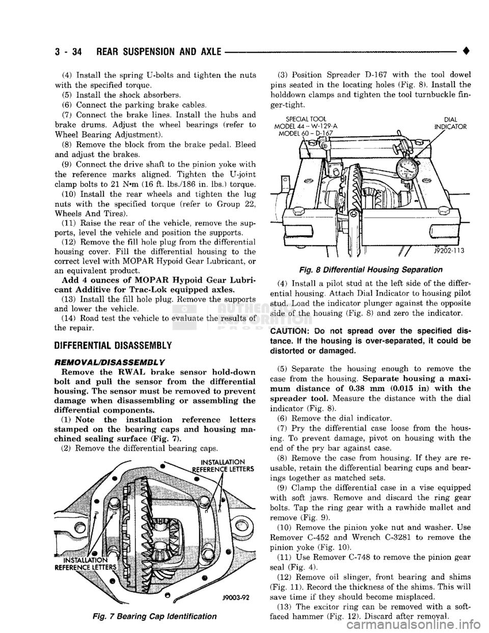
(1) Note the installation reference letters
stamped on the bearing caps and housing ma
chined sealing surface (Fig. 7). (2) Remove the differential bearing caps.
Fig.
7 Bearing Cap
identification
(3) Position Spreader D-167 with the tool dowel
pins seated in the locating holes (Fig. 8). Install the holddown clamps and tighten the tool turnbuckle fin
ger-tight.
SPECIAL TOOL DIAL
MODEL
44-W-129-A
INDICATOR
Fig.
8
Differential
Housing
Separation
(4) Install a pilot stud at the left side of the differ
ential housing. Attach Dial Indicator to housing pilot
stud. Load the indicator plunger against the opposite
side of the housing (Fig. 8) and zero the indicator.
CAUTION:
Do not
spread
over the specified
dis
tance. If the
housing
is over-separated, it
could
be distorted or
damaged.
(5) Separate the housing enough to remove the
case from the housing. Separate housing a maxi
mum distance of 0.38 mm (0.015 in) with the spreader tool. Measure the distance with the dial
indicator (Fig. 8).
(6) Remove the dial indicator. (7) Pry the differential case loose from the hous
ing. To prevent damage, pivot on housing with the
end of the pry bar against case.
(8) Remove the case from housing. If they are re
usable, retain the differential bearing cups and bear ings together as matched sets.
(9) Clamp the differential case in a vise equipped
with soft jaws. Remove and discard the ring gear
bolts.
Tap the ring gear with a rawhide mallet and
remove (Fig. 9).
(10) Remove the pinion yoke nut and washer. Use
Remover C-452 and Wrench C-3281 to remove the
pinion yoke (Fig. 10).
(11) Use Remover C-748 to remove the pinion gear
seal (Fig. 4).
(12) Remove oil slinger, front bearing and shims
(Fig. 11). Record the thickness of the shims. This will
save time if they should become misplaced.
(13) The excitor ring can be removed with a soft-
faced hammer (Fig. 12). Discard after removal.
Page 169 of 1502
3
- 42
REAR
SUSPENSION
AND
AXLE
SPECIAL TOOL
D-111
PRESS
DRIVE
PINION GEAR
SHAFT
REAR BEARING"
INSTALLATION
TOOL
SPECIAL
TOOL
C-4171 J9203-65 DRIVE
PINION GEAR
OIL
SLINGER
J9302-68
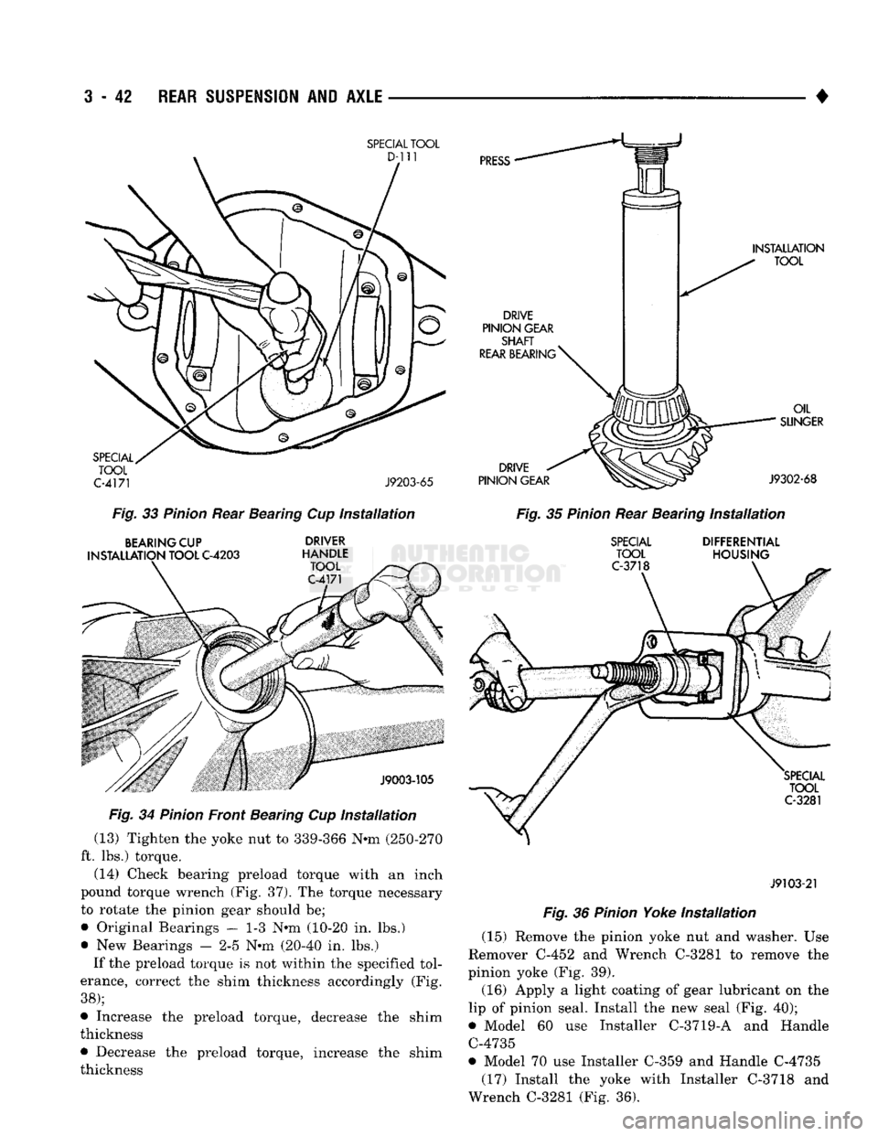
Fig.
33
Pinion
Rear Bearing Cup
installation
Fig.
35
Pinion
Rear Bearing
Installation
BEARING
CUP
INSTALLATION
TOOL
C-4203
DRIVER
HANDLE
TOOL
C-4171
SPECIAL
TOOL
C-3718
DIFFERENTIAL
HOUSING
SPECIAL
TOOL
C-3281
Fig.
34
Pinion
Front Bearing Cup
Installation
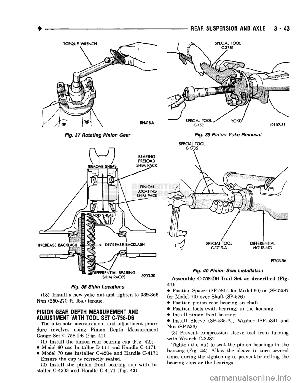
(13) Tighten the yoke nut to 339-366 N-m (250-270
ft. lbs.) torque. (14) Check bearing preload torque with an inch
pound torque wrench (Fig. 37). The torque necessary
to rotate the pinion gear should be;
• Original Bearings — 1-3 Nnn (10-20 in. lbs.)
• New Bearings — 2-5 Nnn (20-40 in. lbs.)
If the preload torque is not within the specified tol
erance, correct the shim thickness accordingly (Fig.
38);
• Increase the preload torque, decrease the shim
thickness
• Decrease the preload torque, increase the shim
thickness
J9103-21
Fig.
36
Pinion
Yoke
Installation
(15) Remove the pinion yoke nut and washer. Use
Remover C-452 and Wrench C-3281 to remove the
pinion yoke (Fig. 39).
(16) Apply a light coating of gear lubricant on the
lip of pinion seal. Install the new seal (Fig. 40);
© Model 60 use Installer C-3719-A and Handle C-4735
• Model 70 use Installer C-359 and Handle C-4735 (17) Install the yoke with Installer C-3718 and
Wrench C-3281 (Fig. 36).
Page 170 of 1502
•
Fig.
37 Rotating
Pinion
Gear
Fig.
38
Shim
Locations
(18) Install a new yoke nut and tighten to 339-366
Nnn (250-270 ft. lbs.) torque.
PINION
GEAR
DEPTH
MEASUREMENT
AND
ADJUSTMENT
WITH
TOOL
SET
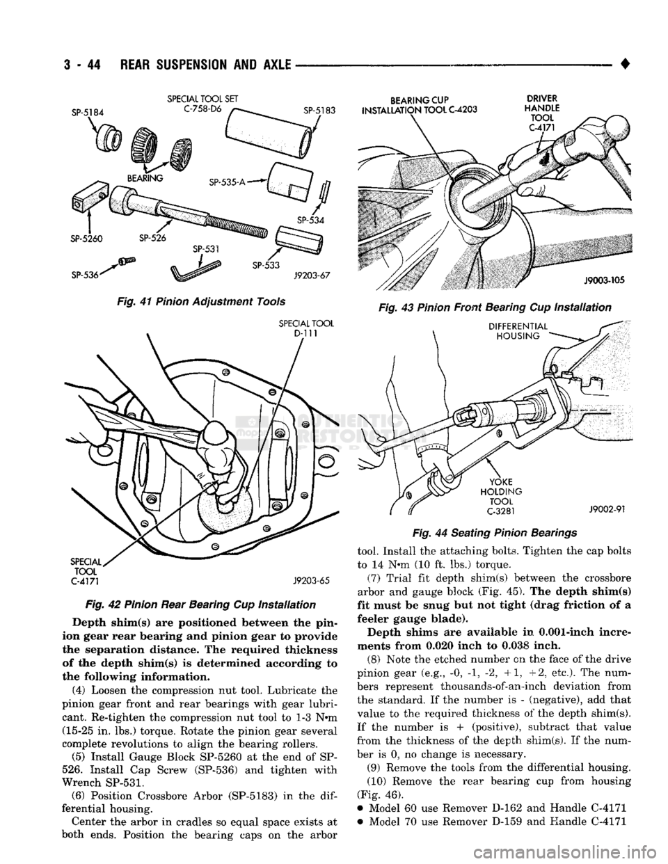
C-758-D6 The alternate measurement and adjustment proce
dure involves using Pinion Depth Measurement Gauge Set C-758-D6 (Fig. 41). (1) Install the pinion rear bearing cup (Fig. 42);
• Model 60 use Installer D-lll and Handle C-4171
• Model 70 use Installer C-4204 and Handle C-4171 Ensure the cup is correctly seated. (2) Install the pinion front bearing cup with In
staller C-4203 and Handle C-4171 (Fig. 43).
REAR
SUSPENSION
AND
AXLE
3 - 43
C-452
J9102-31
Fig.
39
Pinion
Yoke
Removal
SPECIAL
TOOL
C-4735
J9203-56
Fig.
40
Pinion
Seal
Installation
Assemble C-758-D6 Tool Set as described (Fig.
41);
• Position Spacer (SP-5814 for Model 60) or (SP-5587
for Model 70) over Shaft (SP-526)
• Position pinion rear bearing on shaft • Position tools (with bearing) in the housing
• Install pinion front bearing
• Install Sleeve (SP-535-A), Washer (SP-534) and
Nut (SP-533) (3) Prevent compression sleeve tool from turning
with Wrench C-3281.
Tighten the nut to seat the pinion bearings in the
housing (Fig. 44). Allow the sleeve to turn several times during the tightening to prevent brinelling the
bearing cups or the bearings.
Page 171 of 1502
3
- 44
REAR SUSPENSION
AND
AXLE
— __—_ . _ •
SPECIAL
TOOL
SET
Fig.
41
Pinion
Adjustment Tools
SPECIAL
TOOL
C-4171
J9203-65
Fig.
42
Pinion
Rear Bearing Cup
Installation
Depth shim(s) are positioned between the pin
ion gear rear bearing and pinion gear to provide
the separation distance. The required thickness of the depth shim(s) is determined according to
the following information.
(4) Loosen the compression nut tool. Lubricate the
pinion gear front and rear bearings with gear lubri cant. Re-tighten the compression nut tool to 1-3 N-m (15-25 in. lbs.) torque. Rotate the pinion gear several
complete revolutions to align the bearing rollers.
(5) Install Gauge Block SP-5260 at the end of SP-
526.
Install Cap Screw (SP-536) and tighten with
Wrench
SP-531.
(6) Position Crossbore Arbor (SP-5183) in the
dif
ferential housing. Center the arbor in cradles so equal space exists at
both ends. Position the bearing caps on the arbor
BEARING
CUP DRIVER
INSTALLATION
TOOL
C-4203
HANDLE
Fig.
44 Seating
Pinion
Bearings
tool. Install the attaching bolts. Tighten the cap bolts
to 14 N-m (10 ft. lbs.) torque.
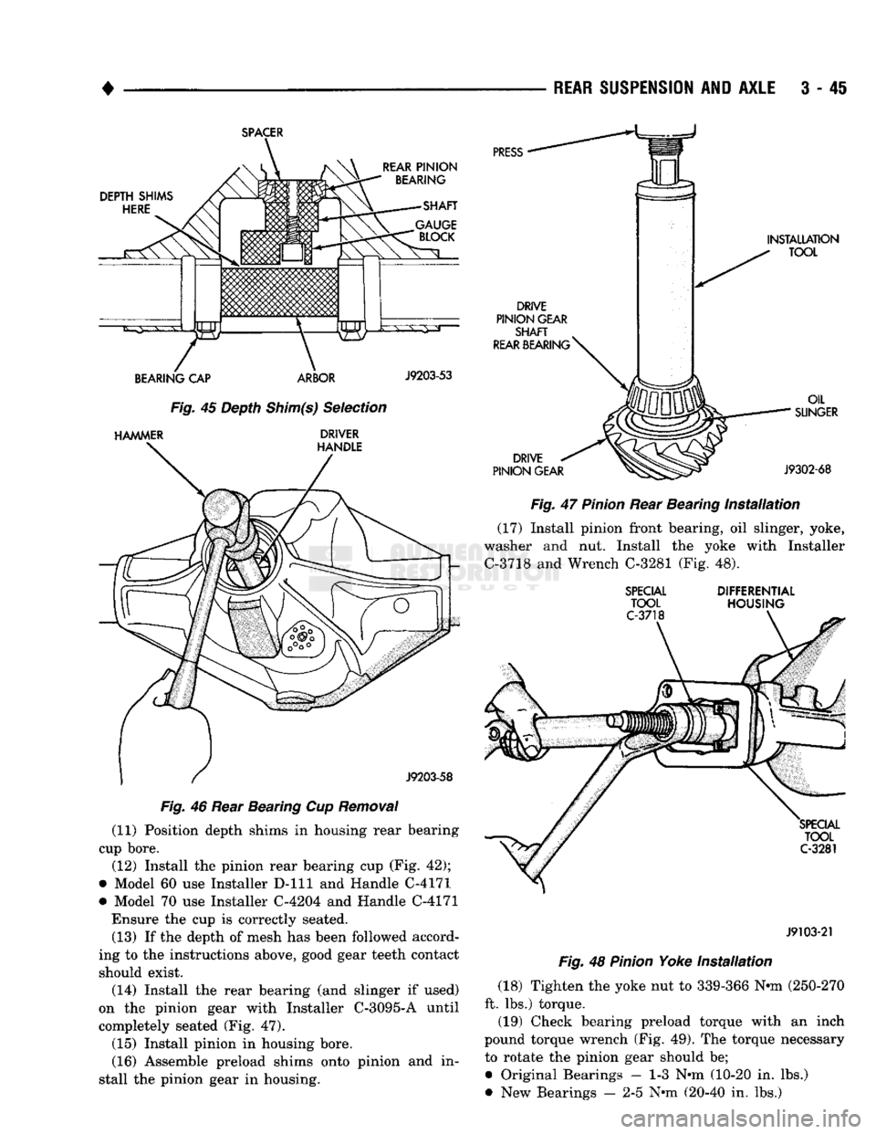
(7) Trial fit depth shim(s) between the crossbore
arbor and gauge block (Fig. 45). The depth shim(s)
fit must be snug but not tight (drag friction of a
feeler gauge blade).
Depth shims are available in 0.001-inch incre
ments from 0.020 inch to 0.038 inch.
(8) Note the etched number on the face of the drive
pinion gear (e.g., -0, -1, -2, +1, +2, etc.). The num
bers represent thousands-of-an-inch deviation from the standard. If the number is - (negative), add that
value to the required thickness of the depth shim(s).
If the number is + (positive), subtract that value
from the thickness of the depth shim(s). If the num
ber is 0, no change is necessary.
(9) Remove the tools from the differential housing.
(10) Remove the rear bearing cup from housing
(Fig. 46),
* Model 60 use Remover D-162 and Handle C-4171 *> Model 70 use Remover D-159 and Handle C-4171
Page 172 of 1502
•
REAR
SUSPENSION
AND
AXLE
3 - 4S
SPACER
DEPTH SHIMS
HERE
REAR
PINION
BEARING
SHAFT
BEARING
CAP ARBOR
J9203-53
Fig.
45 Depth
Shim(s)
Selection
HAMMER
DRIVER HANDLE
J9203-58
Fig.
46 Rear Bearing Cup
Removal
(11) Position depth shims in housing rear bearing
cup bore.
(12) Install the pinion rear bearing cup (Fig. 42);
• Model 60 use Installer D-lll and Handle C-4171
• Model 70 use Installer C-4204 and Handle C-4171 Ensure the cup is correctly seated.
(13) If the depth of mesh has been followed accord
ing to the instructions above, good gear teeth contact
should exist.
(14) Install the rear bearing (and slinger if used)
on the pinion gear with Installer C-3095-A until
completely seated (Fig. 47).
(15) Install pinion in housing bore.
(16) Assemble preload shims onto pinion and in
stall the pinion gear in housing.
PRESS
DRIVE
PINION GEAR
SHAFT
REAR
BEARING
^
INSTALLATION
TOOL
DRIVE
PINION GEAR OIL
SUNGER
J9302-68
Fig.
47
Pinion
Rear Bearing
Installation
(17) Install pinion front bearing, oil slinger, yoke,
washer and nut. Install the yoke with Installer
C-3718 and Wrench C-3281 (Fig. 48).
SPECIAL
TOOL
C-3718
DIFFERENTIAL
HOUSING
SPECIAL
TOOL
C-3281
J9103-21
Fig.
48
Pinion
Yoke
Installation
(18) Tighten the yoke nut to 339-366 Nnn (250-270
ft. lbs.) torque.
(19) Check bearing preload torque with an inch
pound torque wrench (Fig. 49). The torque necessary to rotate the pinion gear should be;
• Original Bearings — 1-3 Nnn (10-20 in. lbs.)
• New Bearings — 2-5 Nnn (20-40 in. lbs.)