1993 DODGE TRUCK Bearing nut torque
[x] Cancel search: Bearing nut torquePage 651 of 1502
9
- 46 3.9L
ENGINE
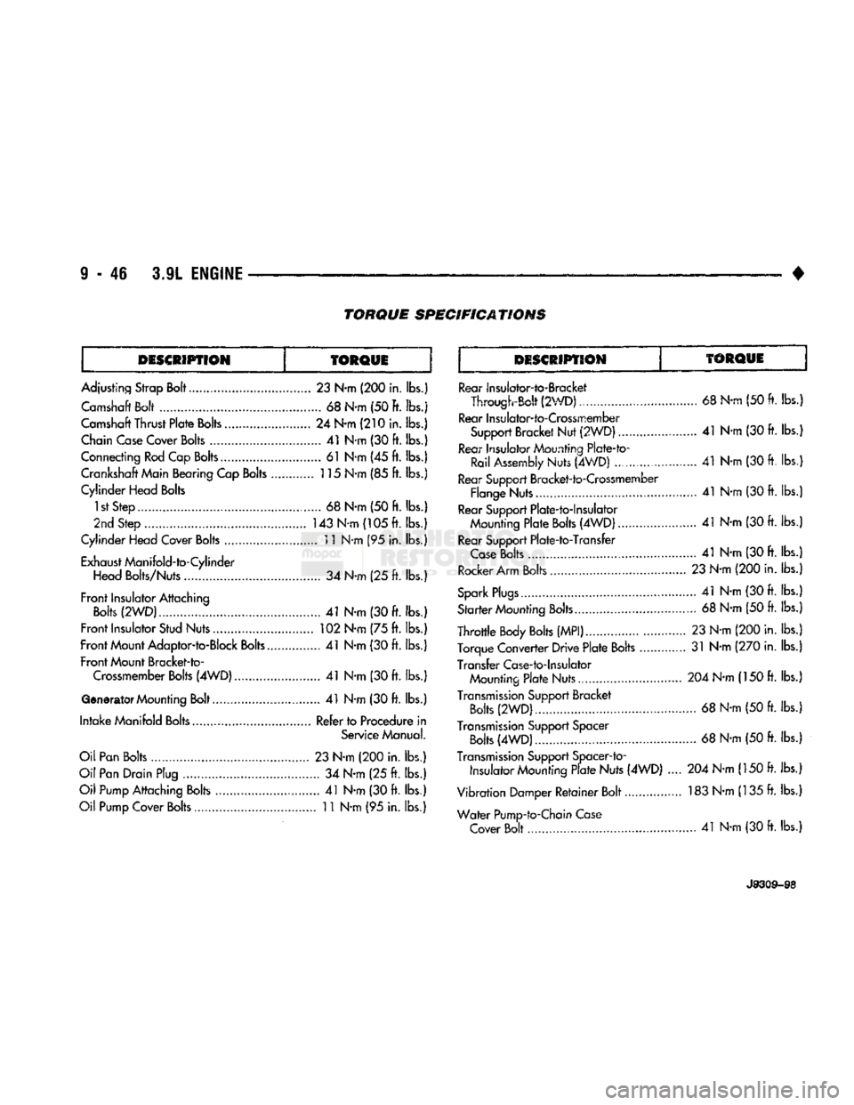
TORQUE
SPECIFICATIONS
DESCRIPTION
TORQUE
DESCRIPTION
TORQUE
Adjusting Strap Bolt.....
23
N-m
(200
in. lbs.) Camshaft Bolt
68
N-m (50 ft. lbs.j
Camshaft Thrust
Plate
Bolts
24
N-m
(210
in. lbs.)
Chain Case Cover
Bolts
41
N-m
(30 ft.
lbs.)
Connecting Rod Cap Bolts
61
N*m
(45 ft.
lbs.) Crankshaft Main Bearing Cap
Bolts
115 N-m
(85 ft.
lbs.}
Cylinder Head Bolts
1st Step
. 68
N-m
(50 ft.
lbs.)
2nd Step
.............................................
143 N-m (105 ft. lbs.)
Cylinder Head Cover
Bolts
11 N-m
(95
in. lbs.)
Exhaust ManifoId-to-Cylinder Head Bolts/Nuts
34
N-m
(25 ft.
lbs.)
Front
Insulator Attaching
Bolts
(2WD)...
41
N-m
(30 ft.
lbs.)
Front
Insulator Stud Nuts
102
N-m
(75 ft.
lbs.)
Front
Mount Adaptor-to-Block
Bolts..
41
N-m
(30 ft.
lbs.)
Front
Mount Bracket-to- Crossmember
Bolts
(4WD).
41
N-m
(30 ft.
lbs.)
Generator Mounting Bolt
41
N-m
(30 ft.
lbs.)
Intake
Manifold Bolts Refer to Procedure
in
Service Manual.
Oil Pan Bolts
23
N-m
(200
in.
lbs.)
Oil Pan Drain Plug
34
N-m
(25 ft.
lbs.)
Oil Pump Attaching Bolts
41
N-m
(30 ft. lbs.)
Oil Pump Cover
Bolts
11
N-m
(95
in. lbs.) Rear Insulalor-to-Bracket
Through-Bolt (2WD)
68
N-rn
(50 ft. lbs.)
Rear Insuiator-to-Crossmember Support Bracket Nut (2WDJ
.. 41
N-m
(30 ft.
lbs.
Rear Insulator Mounting Plate-to- Rail Assembly
Nuts (4WD)
......................
41
N-m
(30 ft. lbs.
Rear Support Bracket-to-Crossmember Flange Nuts....
41
N-m
(30 ft.
lbs.
Rear Support Plate-to-lnsulator Mounting
Plate
Bolts
(4WD) 41
N-m
(30
ft. lbs.
Rear Support Plate-to-Transfer
Case
Bolts
41
N-m
(30 ft.
lbs.
Rocker Arm Bolts
23
N-m
(200
in. lbs.
Spark
Plugs.......
41
N-m
(30 ft. lbs.
Sfarfer Counting
Bolts.
68
N-m
(50 ft.
lbs.
Throttle
Body
Bolts
(MPI)
23
N-m
(200
in. lbs.
Torque Converter Drive
Plate
Bolts
31
N-m
(270
in. lbs.
Transfer Case-to-Insulator Mounting
Plate
Nuts..............
204
N-m
(150
ft. lbs.
Transmission
Support Bracket
Bolts
(2WD)
68
N-m
(50 ft.
lbs.
Transmission
Support Spacer
Bolts
(4WD).
68
N-m
(50 ft.
lbs.
Transmission
Support Spacer-to-
Insulator Mounting
Plate
Nuts (4WD)
.... 204
N-m
(150 ft.
lbs.
Vibration Damper
Retainer
Bolt................ 183 N-m (135
ft.
lbs.
Water
Pump-to-Chain Case Cover Bolt...
41
N-m
(30
ft. lbs.)
J9309-S8
Page 673 of 1502
9
- 68 5.2L
ENGINE
• INSTALLATION
(1) Be sure that compression ring gaps are stag
gered so that neither is in-line with oil ring rail gap.
(2) Before installing the ring compressor, make
sure the oil ring expander ends are butted and the
rail gaps located properly (Fig. 14).
(3) Immerse the piston head and rings in clean en
gine oil. Slide Piston Ring Compressor Tool C-385
over the piston and tighten with the special wrench (part of Tool C-385). Be sure position of rings does
not change during this operation.
(4) Install connecting rod bolt protectors on rod
bolts,
the long protector should be installed on the numbered side of the connecting rod. (5) Rotate crankshaft so that the connecting rod
journal is on the center of the cylinder bore. Be sure connecting rod and cylinder bore number are the same. Insert rod and piston into cylinder bore and
guide rod over the crankshaft journal.
(6) Tap the piston down in cylinder bore, using a
hammer handle. At the same time, guide connecting rod into position on crankshaft journal.
(7) The notch or groove on top of piston must be
pointing toward front of engine. The larger chamfer
of the connecting rod bore must be installed toward
crankshaft journal fillet.
(8) Install rod caps. Be sure connecting rod, con
necting rod cap and cylinder bore number are the same. Install nuts on cleaned and oiled rod bolts and
tighten nuts to 61 N®m (45 ft. lbs.) torque.
(9) Install the oil pan.
(10) Install the cylinder head.
(11) Install the engine into the vehicle.
CRANKSHAFT
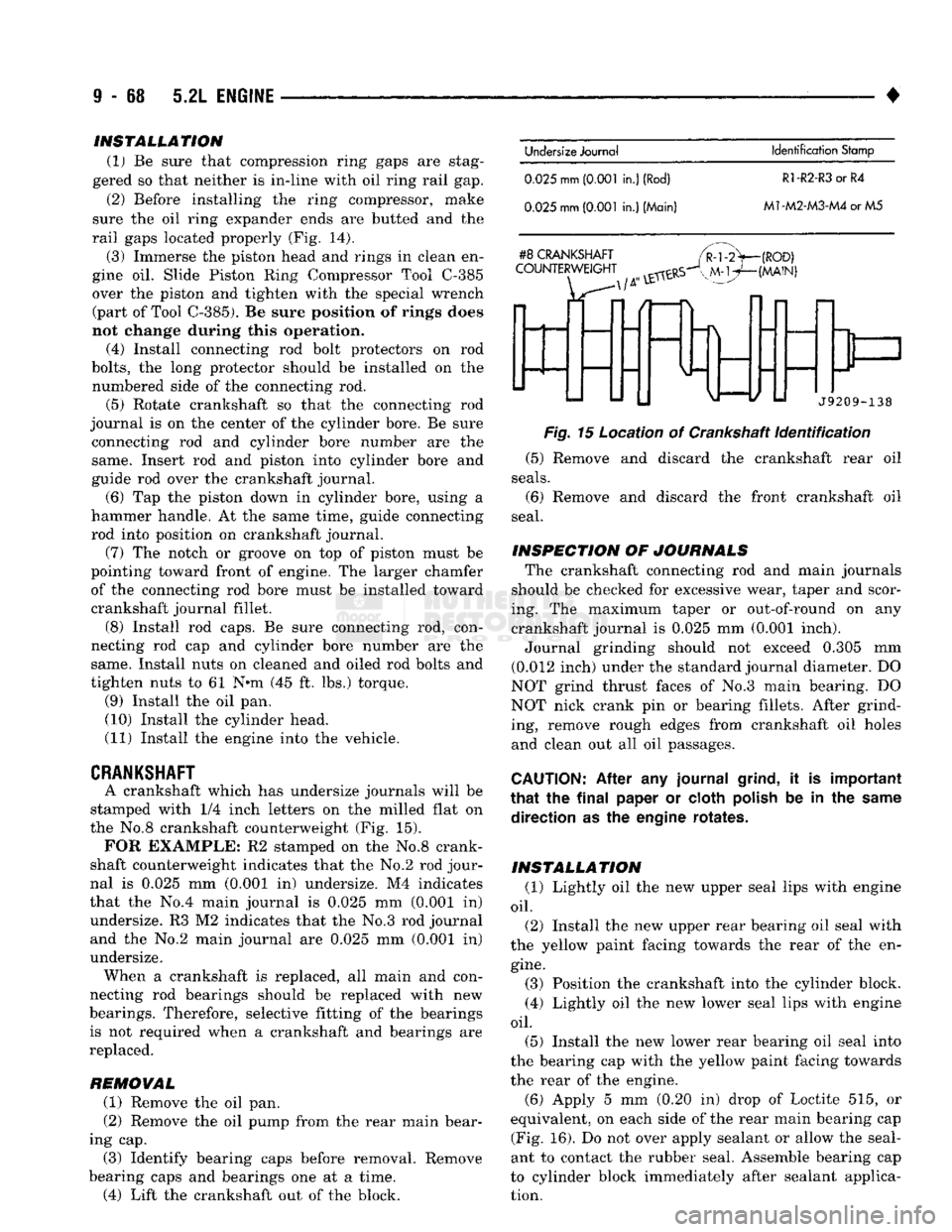
A crankshaft which has undersize journals will be
stamped with 1/4 inch letters on the milled flat on
the No.8 crankshaft counterweight (Fig. 15).
FOR
EXAMPLE: R2 stamped on the No.8 crank
shaft counterweight indicates that the No.2 rod jour
nal is 0.025 mm (0.001 in) undersize. M4 indicates
that the No.4 main journal is 0.025 mm (0.001 in) undersize. R3 M2 indicates that the No.3 rod journal and the No.2 main journal are 0.025 mm (0.Q01 in)
undersize. When a crankshaft is replaced, all main and con
necting rod bearings should be replaced with new
bearings. Therefore, selective fitting of the bearings is not required when a crankshaft and bearings are
replaced.
REMOVAL (1) Remove the oil pan.
(2) Remove the oil pump from the rear main bear
ing cap. (3) Identify bearing caps before removal. Remove
bearing caps and bearings one at a time. (4) Lift the crankshaft out of the block.
Undersize
Journal
Identification
Stamp
0.025
mm
(0.001
in.)
(Rod)
R1-R2-R3
or R4
0.025
mm
(0.001
in.) (Main)
M1-M2-M3-M4
or M5
#8
CRANKSHAFT
COUNTERWEIGHT
(ROD)
(MAIN)
f
J9209-138
Fig.
15 Location of Crankshaft
Identification
(5) Remove and discard the crankshaft rear oil
seals.
(6) Remove and discard the front crankshaft oil
seal.
INSPECTION OF JOURNALS The crankshaft connecting rod and main journals
should be checked for excessive wear, taper and scor
ing. The maximum taper or out-of-round on any crankshaft journal is 0.025 mm (0.001 inch). Journal grinding should not exceed 0.305 mm
(0.012 inch) under the standard journal diameter. DO
NOT grind thrust faces of No.3 main bearing. DO
NOT nick crank pin or bearing fillets. After grind ing, remove rough edges from crankshaft oil holes
and clean out all oil passages.
CAUTION:
After any journal
grind,
it is important
that
the
final
paper or cloth
polish
be in the
same
direction as the engine rotates.
INSTALLATION (1) Lightly oil the new upper seal lips with engine
oil.
(2) Install the new upper rear bearing oil seal with
the yellow paint facing towards the rear of the en
gine.
(3) Position the crankshaft into the cylinder block.
(4) Lightly oil the new lower seal lips with engine
oil.
(5) Install the new lower rear bearing oil seal into
the bearing cap with the yellow paint facing towards
the rear of the engine.
(6)
Apply 5 mm (0.20 in) drop of Loctite 515, or
equivalent, on each side of the rear main bearing cap (Fig. 16). Do not over apply sealant or allow the seal
ant to contact the rubber seal. Assemble bearing cap
to cylinder block immediately after sealant applica tion.
Page 681 of 1502
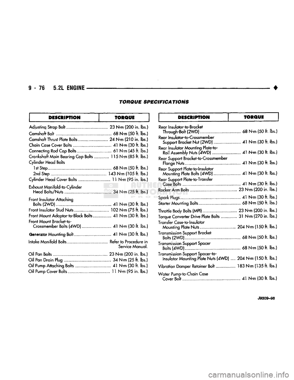
TORQUE
SPECIFICATIONS
DESCRIPTION
TORQUE DESCRIPTION
TORQUE
Adjusting Strap Bolt... 23 N-m (200 in. lbs.)
Camshaft Bolt 68 N-m (50 ft. lbs.)
Camshaft Thrust Plate Bolts........................ 24 N-m (210 in. lbs.)
Chain Case Cover Bolts 41 N-m (30 ft. lbs.)
Connecting Rod Cap Bolts 61 N-m (45 ft. lbs.)
Crankshaft Main Bearing Cap Bolts 115 N-m (85 ft. lbs.)
Cylinder Head Bolts 1st Step 68 N-m (50 ft. lbs.)
2nd Step 143 N-m (105 ft. lbs.)
Cylinder Head Cover Bolts 11 N-m (95 in. lbs.)
Exhaust Manifold-to-Cylinder Head Bolts/Nuts 34 N-m (25 ft. lbs.)
Front Insulator Attaching Bolts (2WD).. 41 N-m (30 ft. lbs.)
Front Insulator Stud Nuts 102 N-m (75 ft. lbs.) Front Mount Adaptor-to-Block Bolts 41 N-m (30 ft. lbs.)
Front Mount Bracket-to- Crossmember Bolts (4WD) 41 N-m (30 ft. lbs.)
Generator
Mounting Bolt 41 N-m (30 ft. lbs.)
Intake Manifold Bolts Refer to Procedure in Service Manual.
Oil Pan Bolts 23 N-m (200 in. lbs.)
Oil Pan Drain Plug 34 N-m (25 ft. lbs.)
Oil Pump Attaching Bolts 41 N-m (30 ft. lbs.) Oil Pump Cover Bolts.. 11 N-m (95 in. lbs.) Rear Insulator-to-Bracket
Through-Bolt (2WD)................................. 68 N-m (50 ft. lbs.
Rear Insulator-to-Crossmember Support Bracket Nut (2WD) 41 N-m (30 ft. lbs.
Rear Insulator Mounting Plate-to- Rail Assembly Nuts (4WD) 41 N-m (30 ft. lbs.
Rear Support Bracket-to-Crossmember Flange Nuts 41 N-m (30
ft.
lbs.
Rear Support Plate-to-lnsulator Mounting Plate Bolts (4WD) 41 N-m (30
ft.
lbs.
Rear Support Plate-to-Transfer Case Bolts 41 N-m (30
ft.
lbs.
Rocker Arm Bolts 23 N-m (200 in. lbs.
Spark Plugs.... 41 N-m (30 ft. lbs.
Starter Mounting Bolts 68 N-m (50 ft. lbs.
Throttle Body Bolts (MPI)... 23 N-m (200 in. lbs. Torque Converter Drive Plate Bolts 31 N-m (270 in. lbs.
Transfer Case-to-Insulator Mounting Plate Nuts.... 204 N-m (150 ft. lbs.
Transmission Support Bracket Bolts (2WD).... 68 N-m (50 ft. lbs.
Transmission Support Spacer Bolts (4WD) 68 N-m (50
ft.
lbs.
Transmission Support Spacer-to- Insulator Mounting Plate Nuts (4WD) .... 204 N-m (150 ft. lbs.
Vibration Damper Retainer Bolt 183 N-m (135
ft.
lbs.
Water Pump-to-Chain Case Cover Bolt 41 N-m (30
ft.
Ibs.j
J9309-98
Page 697 of 1502
9
- 92 5.9L
ENGINE
•
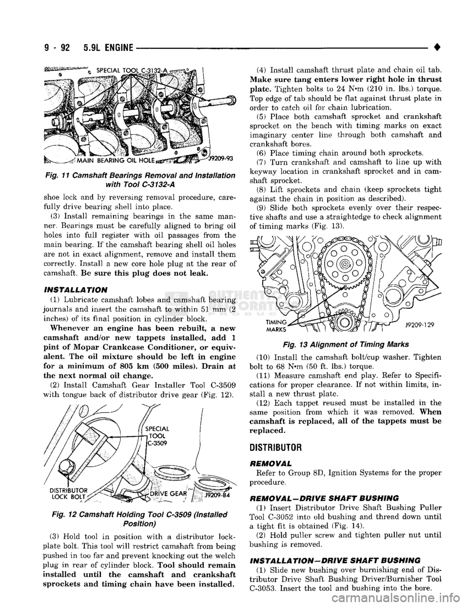
Fig.
11 Camshaft
Bearings
Removal
and
Installation
with Tool
C-3132-A
shoe lock and by reversing removal procedure, care
fully drive bearing shell into place. (3) Install remaining bearings in the same man
ner. Bearings must be carefully aligned to bring oil
holes into full register with oil passages from the main bearing. If the camshaft bearing shell oil holes
are not in exact alignment, remove and install them
correctly. Install a new core hole plug at the rear of
camshaft. Be sure this plug does not leak.
INSTALLATION (1) Lubricate camshaft lobes and camshaft bearing
journals and insert the camshaft to within 51 mm (2 inches) of its final position in cylinder block.
Whenever an engine has been rebuilt, a new
camshaft and/or new tappets installed, add 1
pint of Mopar Crankcase Conditioner, or equiv alent. The oil mixture should be left in engine
for a minimum of 805 km (500 miles). Drain at
the next normal oil change.
(2)
Install Camshaft Gear Installer Tool C-3509
with tongue back of distributor drive gear (Fig. 12).
Fig.
12 Camshaft
Holding
Tool C-3509 (Installed
Position)
(3) Hold tool in position with a distributor lock-
plate bolt. This tool will restrict camshaft from being
pushed in too far and prevent knocking out the welch
plug in rear of cylinder block. Tool should remain
installed until the camshaft and crankshaft sprockets and timing chain have been installed. (4) Install camshaft thrust plate and chain oil tab.
Make sure tang enters lower right hole in thrust
plate. Tighten bolts to 24 N-m (210 in. lbs.) torque.
Top edge of tab should be flat against thrust plate in
order to catch oil for chain lubrication.
(5) Place both camshaft sprocket and crankshaft
sprocket on the bench with timing marks on exact
imaginary center line through both camshaft and
crankshaft bores. (6) Place timing chain around both sprockets.
(7) Turn crankshaft and camshaft to line up with
keyway location in crankshaft sprocket and in cam shaft sprocket. (8) Lift sprockets and chain (keep sprockets tight
against the chain in position as described). (9) Slide both sprockets evenly over their respec
tive shafts and use a straightedge to check alignment of timing marks (Fig. 13).
Fig.
13
Alignment
of Timing Marks
(10) Install the camshaft bolt/cup washer. Tighten
bolt to 68 N-m (50 ft. lbs.) torque.
(11) Measure camshaft end play. Refer to Specifi
cations for proper clearance. If not within limits, in stall a new thrust plate.
(12) Each tappet reused must be installed in the
same position from which it was removed. When
camshaft is replaced, all of the tappets must be
replaced.
DISTRIBUTOR
REMOVAL Refer to Group 8D, Ignition Systems for the proper
procedure.
REMOVAL-DRIVE SHAFT BUSHING (1) Insert Distributor Drive Shaft Bushing Puller
Tool C-3052 into old bushing and thread down until a tight fit is obtained (Fig. 14).
(2) Hold puller screw and tighten puller nut until
bushing is removed.
INSTALLATION-DRIVE SHAFT BUSHING (1) Slide new bushing over burnishing end of Dis
tributor Drive Shaft Bushing Driver/Burnisher Tool
C-3053.
Insert the tool and bushing into the bore.
Page 703 of 1502
(2) Before installing the ring compressor, make
sure the oil ring expander ends are butted and the
rail gaps located properly (Fig. 14).
(3) Immerse the piston head and rings in clean en
gine oil. Slide Piston Ring Compressor Tool C-385
over the piston and tighten with the special wrench (part of Tool C-385). Be
sure position
of
rings does
not change
during this operation.
(4) Install connecting rod bolt protectors on rod
bolts,
the long protector should be installed on the numbered side of the connecting rod. (5) Rotate crankshaft so that the connecting rod
journal is on the center of the cylinder bore. Be sure connecting rod and cylinder bore number are the same. Insert rod and piston into cylinder bore and
guide rod over the crankshaft journal.
(6) Tap the piston down in cylinder bore, using a
hammer handle. At the same time, guide connecting
rod into position on crankshaft journal. (7) The notch or groove on top of piston must be
pointing toward front of engine. The larger chamfer of the connecting rod bore must be Installed toward
crankshaft journal fillet.
(8) Install rod caps. Install nuts on cleaned and
oiled rod bolts and tighten nuts to 61 N*m (45 ft. lbs.)
torque. (9) Install the oil pan.
(10) Install the cylinder head.
(11) Install the engine Into the vehicle.
CRANKSHAFT
A crankshaft which has undersize journals will be
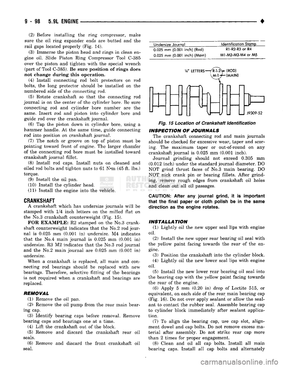
stamped with 1/4 inch letters on the milled flat on
the No.3 crankshaft counterweight (Fig. 15). FOR EXAMPLE: R2 stamped on the No.3 crank
shaft counterweight indicates that the No.2 rod jour
nal is 0.025 mm (0.001 in) undersize. M4 indicates
that the No.4 main journal is 0.025 mm (0.001 in) undersize. R3 M2 indicates that the No.3 rod journal
and the No.2 main journal are 0.025 mm (0.001 In)
undersize. When a crankshaft is replaced, all main and con
necting rod bearings should be replaced with new
bearings. Therefore, selective fitting of the bearings is not required when a crankshaft and bearings are
replaced.
REMOVAL
(1) Remove the oil pan.
(2) Remove the oil pump from the rear main bear
ing cap.
(3) Identify bearing caps before removal. Remove
bearing caps and bearings one at a time. (4) Lift the crankshaft out of the block.
(5) Remove and discard the crankshaft rear oil
seals.
(6) Remove and discard the front crankshaft oil
seal. Undersize Journal
Identification
Stamp
0.025
mm
(0.001
inch) (Rod)
0.025
mm
(0.001
inch) (Main)
R1-R2-R3
or R4
M1-AA2-M3-AA4
or AA5
V/
LETTERS—/R-l-2>
(ROD)
VM-WHMAIN)
J9309-52
Fig.
15 Location of Crankshaft
identification
INSPECTION
OF
JOURNALS
The crankshaft connecting rod and main journals
should be checked for excessive wear, taper and scor
ing. The maximum taper or out-of-round on any
crankshaft journal is 0.025 mm (0.001 inch).
Journal grinding should not exceed 0.305 mm
(0.012 inch) under the standard journal diameter. DO
NOT grind thrust faces of No.3 main bearing. DO
NOT nick crank pin or bearing fillets. After grind ing, remove rough edges from crankshaft oil holes
and clean out all oil passages.
CAUTION:
After any journal
grind,
it is important
that
the
final
paper or cloth
polish
be in the
same
direction as the engine rotates.
INSTALLATION
(1) Lightly oil the new upper seal lips with engine
oil.
(2) Install the new upper rear bearing oil seal with
the yellow paint facing towards the rear of the en
gine.
(3) Position the crankshaft into the cylinder block.
(4) Lightly oil the new lower seal lips with engine
oil.
(5) Install the new lower rear bearing oil seal into
the bearing cap with the yellow paint facing towards the rear of the engine. (6) Apply 5 mm (0.20 in) drop of Loctite 515, or
equivalent, on each side of the rear main bearing cap (Fig. 16). Do not over apply sealant or allow the seal
ant to contact the rubber seal. Assemble bearing cap
to cylinder block immediately after sealant applica
tion.
(7) To align the bearing cap, use cap slot, align
ment dowel and cap bolts. Do not remove excess ma
terial after assembly. Do not strike rear cap more
than 2 times for proper engagement.
(8) Clean and oil all cap bolts. Install all main
bearing caps. Install all cap bolts and alternately
Page 711 of 1502
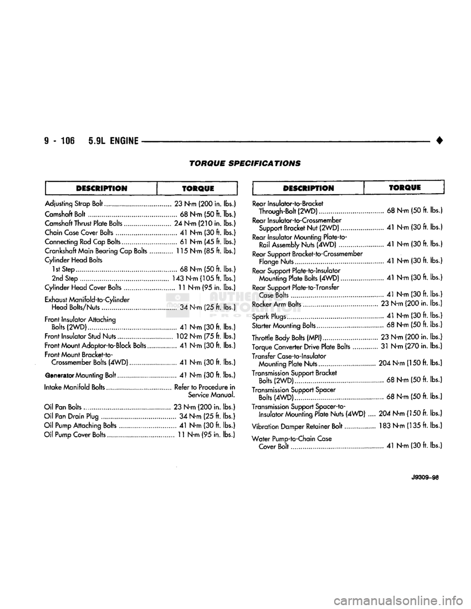
TORQUE
SPECIFICATIONS
DESCRIPTION TORQUE DESCRIPTION
TORQUE
Adjusting Strap Bolt 23 N-m (200 in. lbs.)
Camshaft Bolt 68 N-m (50
ft.
lbs.)
Camshaft Thrust Plate Bolts 24 N-m (210 in. lbs.)
Chain Case Cover Bolts 41 N-m (30 ft. lbs.)
Connecting Rod Cap Bolts.. 61 N-m (45 ft. lbs.)
Crankshaft Main Bearing Cap Bolts 115 N-m (85 ft. lbs.)
Cylinder Head Bolts 1st Step 68
N-m
(50 ft. lbs.)
2nd Step 143 N-m (105 ft. lbs.)
Cylinder Head Cover Bolts .......................... 11 N-m (95 in. lbs.)
Exhaust Manifold-to-Cylinder Head Bolts/Nuts 34 N-m (25 ft. lbs.)
Front Insulator Attaching Bolts (2WD) 41 N-m (30 ft. lbs.)
Front Insulator Stud Nuts 102 N-m (75 ft. lbs.)
Front Mount Adaptor-to-Block Bolts 41 N-m (30 ft. lbs.)
Front Mount Bracket-to- Crossmember Bolts (4WD) 41 N-m (30 ft. lbs.)
Generator Mounting Bolt 41 N-m (30 ft. lbs.)
Intake Manifold Bolts Refer to Procedure in Service Manual.
Oil Pan Bolts 23 N-m (200 in. lbs.)
Oil Pan Drain Plug 34 N-m (25 ft. lbs.)
Oil Pump Attaching Bolts 41 N-m (30 ft. lbs.)
Oil Pump Cover Bolts 11 N-m (95 in. lbs.) Rear Insulator-to-Bracket
Through-Bolt (2WD) 68 N-m (50 ft. lbs.
Rear Insulator-to-Crossmember Support Bracket Nut
(2WD)
41
N-m (30
ft.
lbs.
Rear Insulator Mounting Plate-fo- Rail Assembly Nuts (4WD) 41 N-m (30
ft.
lbs.
Rear Support Bracket-to-Crossmember Flange Nuts 41 N-m (30
ft.
lbs.
Rear Support Plate-to-lnsulator Mounting Plate Bolts (4WD) 41 N-m (30
ft.
lbs.
Rear Support Plate-to-Transfer Case Bolts 41 N-m (30
ft.
lbs.
Rocker Arm Bolts 23 N-m (200 in. lbs.
Spark Plugs....... 41 N-m (30
ft.
lbs.
Starter Mounting Bolts. 68 N-m (50
ft.
lbs.
Throttle Body Bolts (MPI) 23 N-m (200 in. lbs.
Torque Converter Drive Plate Bolts 31 N-m (270 in. lbs.
Transfer Case-to-lnsulator Mounting Plate Nuts... 204 N-m (150
ft.
lbs.
Transmission Support Bracket Bolts (2WD) 68 N-m (50
ft.
lbs.
Transmission Support Spacer Bolts (4WD) 68 N-m (50 ft. lbs.
Transmission Support Spacer-to- insulator Mounting Plate Nuts (4WD) .... 204 N-m (150 ft. lbs.
Vibration Damper Retainer Bolt 183 N-m (135 ft. lbs.
Water Pump-to-Chain Case Cover Bolt 41 N-m (30 ft. lbs.)
J9309-98
Page 733 of 1502
9
- 128 5.9L
(DIESEL)
ENGINE
•
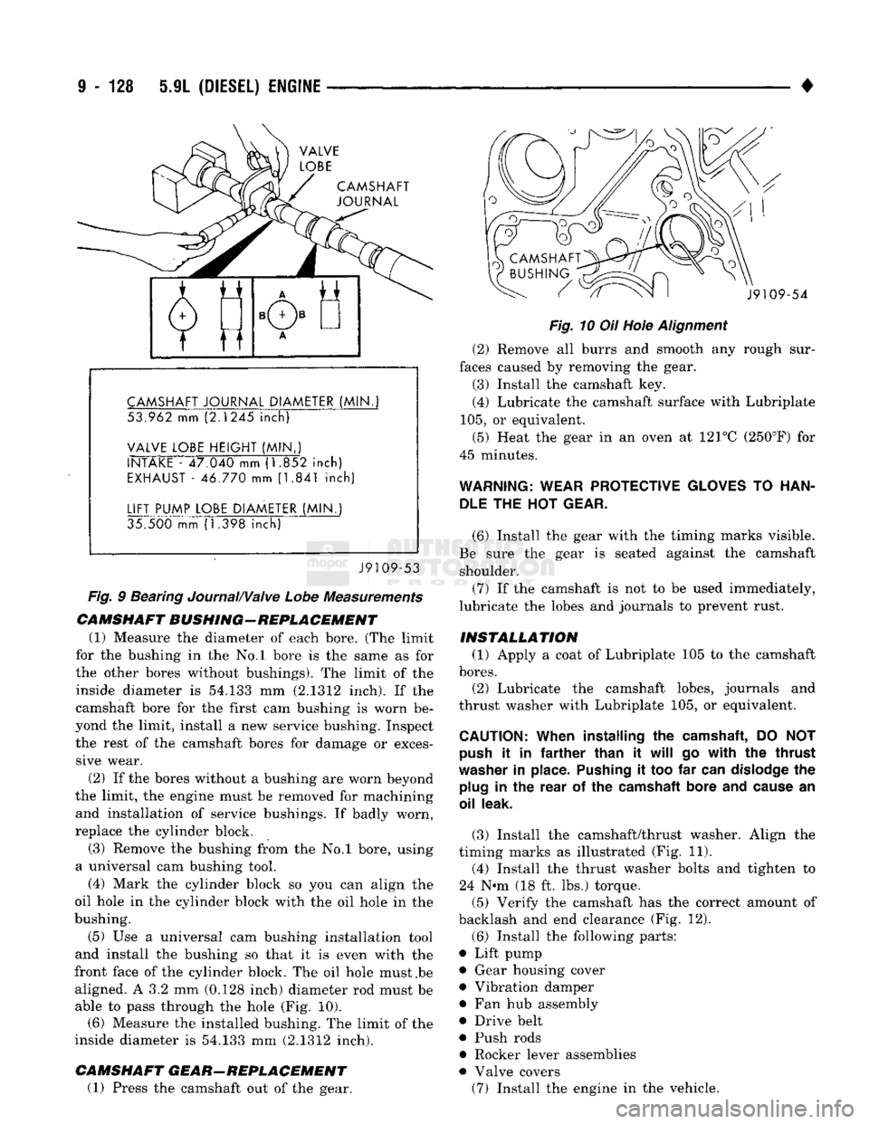
CAMSHAFT
JOURNAL
CAMSHAFT
JOURNAL
DIAMETER
(MIN.
53.962 mm (2.1245
inch)
VALVE
LOBE
HEIGHT
(MIN..)
INTAKE
- 47.040 mm (1.852
inch)
EXHAUST
- 46.770 mm (1.841
inch)
LIFT
PUMP
LOBE
DIAMETER
(MIN.)
35.500 mm (1.398
inch)
J9109-53
Fig.
9 Bearing Journal/Valve
Lobe
Measurements
CAMSHAFT
BUSHING-REPLACEMENT
(1) Measure the diameter of each bore. (The limit
for the bushing in the No.l bore is the same as for
the other bores without bushings). The limit of the inside diameter is 54.133 mm (2.1312 inch). If the
camshaft bore for the first cam bushing is worn be
yond the limit, install a new service bushing. Inspect the rest of the camshaft bores for damage or exces sive wear.
(2) If the bores without a bushing are worn beyond
the limit, the engine must be removed for machining and installation of service bushings. If badly worn,
replace the cylinder block.
(3) Remove the bushing from the No.l bore, using
a universal cam bushing tool.
(4) Mark the cylinder block so you can align the
oil hole in the cylinder block with the oil hole in the
bushing.
(5) Use a universal cam bushing installation tool
and install the bushing so that it is even with the
front face of the cylinder block. The oil hole must .be aligned. A 3.2 mm (0.128 inch) diameter rod must be able to pass through the hole (Fig. 10). (6) Measure the installed bushing. The limit of the
inside diameter is 54.133 mm (2.1312 inch).
CAMSHAFT
GEAR-REPLACEMENT
(1) Press the camshaft out of the gear. J9109-54
Fig.
10 Oil Hole
Alignment
(2) Remove all burrs and smooth any rough sur
faces caused by removing the gear. (3) Install the camshaft key.
(4) Lubricate the camshaft surface with Lubriplate
105,
or equivalent.
(5) Heat the gear in an oven at 121°C (250°F) for
45 minutes.
WARNING:
WEAR
PROTECTIVE
GLOVES
TO
HAN
DLE
THE HOT
GEAR.
(6) Install the gear with the timing marks visible.
Be sure the gear is seated against the camshaft shoulder.
(7) If the camshaft is not to be used immediately,
lubricate the lobes and journals to prevent rust.
INSTALLATION
(1) Apply a coat of Lubriplate 105 to the camshaft
bores.
(2) Lubricate the camshaft lobes, journals and
thrust washer with Lubriplate 105, or equivalent.
CAUTION:
When
installing
the
camshaft,
DO NOT
push
it in
farther
than
it
will
go
with
the
thrust
washer
in
place.
Pushing
it too far
can
dislodge
the
plug
in the
rear
of the
camshaft
bore
and
cause
an
oil
leak.
(3) Install the camshaft/thrust washer. Align the
timing marks as illustrated (Fig. 11). (4) Install the thrust washer bolts and tighten to
24 N-m (18 ft. lbs.) torque.
(5) Verify the camshaft has the correct amount of
backlash and end clearance (Fig. 12).
(6) Install the following parts:
• Lift pump • Gear housing cover
• Vibration damper
• Fan hub assembly
• Drive belt
• Push rods
• Rocker lever assemblies
• Valve covers (7) Install the engine in the vehicle.
Page 756 of 1502
5.9L
(DIESEL)
ENGINE
9-153
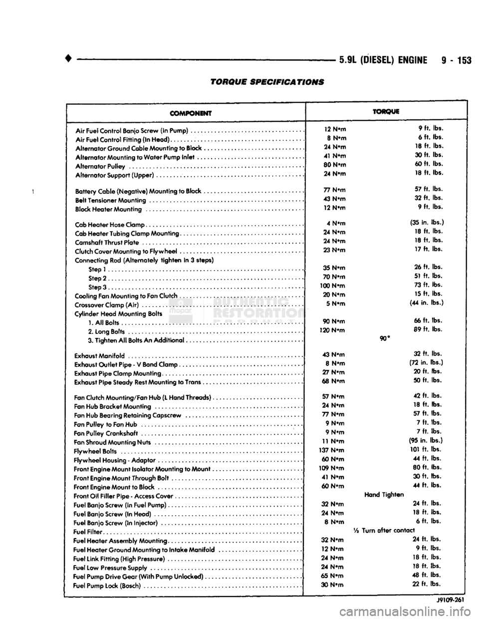
TORQUE
SPECIFICATIONS
COMPONENT
Air
Fuel
Control
Banjo Screw (In Pump) ....
Air
Fuel
Control
Fitting
(In
Head)
Alternator
Ground Cable Mounting to
Block
Alternator
Mounting to
Water
Pump
Inlet
..
Alternator
Pulley
Alternator
Support
(Upper)
Battery
Cable
(Negative)
Mounting to Block ,
Belt
Tensioner
Mounting
Block
Heater
Mounting
Cab
Heater
Hose
Clamp
Cab
Heater
Tubing
Clamp Mounting.......
Camshaft
Thrust
Plate
Clutch Cover Mounting to
Flywheel
...
Connecting Rod
(Alternately
tighten
in 3 steps) Step 1
Step 2
Step 3 .
Cooling Fan Mounting to
Fan
Clutch
Crossover
Clamp (Air)
Cylinder
Head
Mounting Bolts
1.
All
Bolts....
2.
Long
Bolts
.........
3.
Tighten
All
Bolts
An
Additional
Exhaust
Manifold
Exhaust
Outlet
Pipe
- V
Band
Clamp
Exhaust
Pipe
Clamp Mounting
Exhaust
Pipe
Steady
Rest
Mounting to Trans .
Fan
Clutch Mounting/Fan Hub
(L
Hand
Threads)..
Fan Hub
Bracket
Mounting
Fan Hub Bearing
Retaining
Capscrew
Fan
Pulley
to
Fan
Hub
Fan
Pulley
Crankshaft .
Fan
Shroud
Mounting Nuts
Flywheel
Bolts
Flywheel
Housing
- Adaptor
Front
Engine
Mount Isolator Mounting to Mount..
Front
Engine
Mount Through Bolt
Front
Engine
Mount to Block
Front
Oil
Filler
Pipe
-
Access
Cover
Fuel
Banjo Screw (In
Fuel
Pump)
Fuel
Banjo Screw (In
Head)
Fuel
Banjo Screw (In
Injector)
Fuel
Filter
Fuel
Heater
Assembly
Mounting
Fuel
Heater
Ground Mounting to
Intake
Manifold
Fuel
Link
Fitting
(High Pressure)
Fuel
Low Pressure Supply
Fuel
Pump
Drive
Gear
(With
Pump
Unlocked)
Fuel
Pump Lock (Bosch)
TORQUE
12 N-m 9 ft. lbs.
8 N-m 6 ft. lbs.
24 N-m 18 ft. lbs.
41 N*m 30 ft. lbs.
80 N-m 60 ft. lbs.
24 N-m 18 ft. lbs.
77 N-m 57 ft. lbs.
43 N-m 32 ft. lbs.
12 N-m 9 ft. lbs.
4 N-m (35 in. lbs.)
24 N-m 18 ft. lbs.
24 N-m 18 ft. lbs.
23 N-m 17 ft. lbs.
35 N-m 26 ft. lbs.
70 N-m 51 ft. lbs.
100 N-m 73 ft. lbs.
20 N-m 15 ft. lbs.
5
N-m (44 in. lbs.)
90 N-m 66 ft. lbs.
120 N-m 89 ft. lbs.
90°
43 N-m 32 ft. lbs.
8 N-m (72 in. lbs.)
27 N-m 20 ft. lbs.
68 N-m 50 ft. lbs.
57 N-m 42 ft. lbs.
24 N-m 18 ft. lbs.
77 N-m 57 ft. lbs.
9 N-m 7 ft. lbs.
9 N-m 7 ft. lbs.
11 N-m (95 in. lbs.)
137 N-m 101 ft. lbs.
60 N-m 44 ft. lbs.
109 N-m 80 ft. lbs.
41 N-m 30 ft. lbs.
60 N-m 44 ft. lbs.
Hand
Tighten
32 N-m 24 ft. lbs.
24 N-m 18 ft. lbs.
8 N-m 6 ft. lbs.
Vi
Turn
after
contact
32 N-m 24 ft. lbs.
12 N-m 9 ft. lbs.
24 N-m 18 ft. lbs.
24 N-m 18 ft. lbs.
65 N-m 48 ft. lbs.
30 N-m 22 ft. lbs.
J9109-261