1991 ACURA NSX check engine
[x] Cancel search: check enginePage 1126 of 1640
Intake Air System
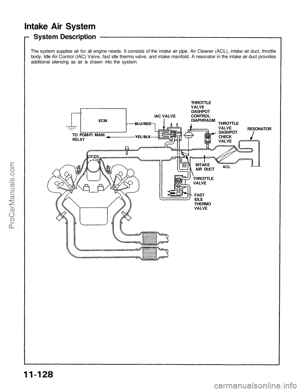
System Description
The system supplies air for all engine needs. It consists of the intake air pipe. Air Cleaner (ACL), intake air duct, throttle
body. Idle Air Control (IAC) Valve, fast idle thermo valve, and intake manifold. A resonator in the intake air duct provides
additional silencing as air is drawn into the system.
FAST
IDLE
THERMO
VALVE
ECM
IAC VALVE
TO PGM-FI MAIN
RELAY
THROTTLE
VALVE
INTAKE
AIR DUCT
ACL
THROTTLE
VALVE
DASHPOT
CONTROL
DIAPHRAGM
THROTTLE
VALVE
RESONATOR
DASHPOT
CHECK
VALVEProCarManuals.com
Page 1128 of 1640
Intake Air System
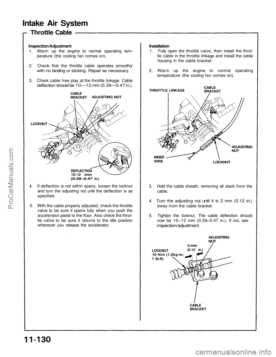
Inspection/Adjustment
1. Warm up the engine to normal operating tem- perature (the cooling fan comes on).
2. Check that the throttle cable operates smoothly
with no binding or sticking. Repair as necessary.
3. Check cable free play at the throttle linkage. Cable
deflection should be 10—12 mm (0.39—0.47 in.).
Installation
1. Fully open the throttle valve, then install the throt-
tle cable in the throttle linkage and install the cablehousing in the cable bracket.
2. Warm up the engine to normal operating temperature (the cooling fan comes on).
4. If deflection is not within specs, loosen the locknut and turn the adjusting nut until the deflection is as
specified.
5. With the cable properly adjusted, check the throttle valve to be sure it opens fully when you push the
accelerator pedal to the floor. Also check the throt-
tle valve to be sure it returns to the idle position whenever you release the accelerator. 3. Hold the cable sheath, removing all slack from the
cable.
4. Turn the adjusting nut until it is 3 mm (0.12 in.)
away from the cable bracket.
5. Tighten the locknut. The cable deflection should now be 10–12 mm (0.39–0.47 in.). If not, see
inspection/adjustment.
CABLE
BRACKET
LOCKNUT
10 N .
m (1.0kg-m,
7 Ib-ft)
3 mm
(0.12 in.)
ADJUSTING
NUT
DEFLECTION
10–12
mm
(0.39–0.47
in.)
ADJUSTING NUT
CABLE
BRACKET
LOCKNUT
INNER
WIRE
THROTTLE LINKAGE
LOCKNUT
ADJUSTING
NUT
CABLE
BRACKET
Throttle CableProCarManuals.com
Page 1134 of 1640
Intake Air System
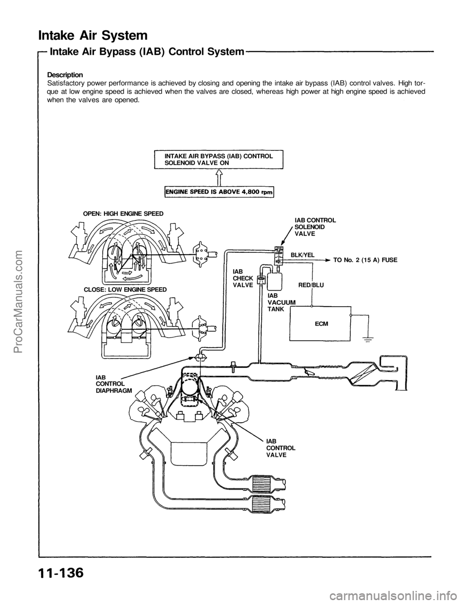
Description
Satisfactory power performance is achieved by closing and opening the intake air bypass (IAB) control valves. High tor-
que at low engine speed is achieved when the valves are closed, whereas high power at high engine speed is achieved
when the valves are opened.
Intake Air Bypass (IAB) Control System
OPEN: HIGH ENGINE SPEED
INTAKE AIR BYPASS (IAB) CONTROL
SOLENOID VALVE ON
IAB
CHECK
VALVE
CLOSE: LOW ENGINE SPEED
IAB
CONTROL
DIAPHRAGM
IAB
CONTROL
VALVE
ECM
IAB
VACUUM
TANK
IAB CONTROL
SOLENOID
VALVE
TO No. 2 (15 A) FUSE
BLK/YEL
RED/BLUProCarManuals.com
Page 1141 of 1640
Positive Crankcase Ventilation (PCV) System
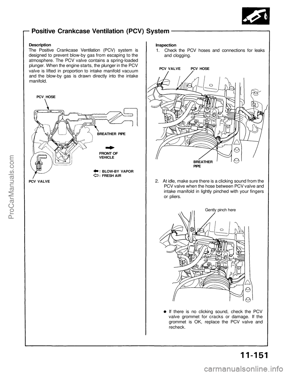
Description
The Positive Crankcase Ventilation (PCV) system is
designed to prevent blow-by gas from escaping to the
atmosphere. The PCV valve contains a spring-loaded
plunger. When the engine starts, the plunger in the PCV
valve is lifted in proportion to intake manifold vacuum
and the blow-by gas is drawn directly into the intake
manifold.
PCV HOSE
BREATHER PIPE
FRONT OF
VEHICLE
BLOW-BY VAPOR
FRESH AIR
PCV VALVE
If there is no clicking sound, check the PCV
valve grommet for cracks or damage. If the
grommet is OK, replace the PCV valve and
recheck.
Gently pinch here
2. At idle, make sure there is a clicking sound from the
PCV valve when the hose between PCV valve and
intake manifold in lightly pinched with your fingers
or pliers.
BREATHER
PIPE
PCV VALVE PCV HOSE
Inspection
1. Check the PCV hoses and connections for leaks
and clogging.ProCarManuals.com
Page 1160 of 1640
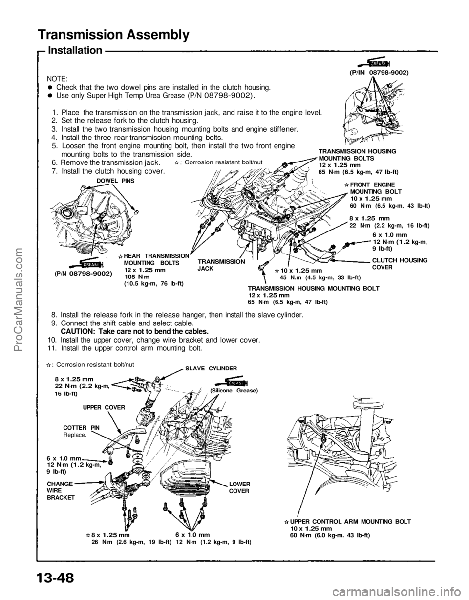
Transmission Assembly
Installation
NOTE:
Check that the two dowel pins are installed in the clutch housing.
Use
only Super High Temp
Urea
Grease
(P/N
08798-9002).
1. Place the transmission on the transmission jack, and raise it to the engine level.
2. Set the release fork to the clutch housing.
3. Install the two transmission housing mounting bolts and engine stiffener.
4. Install the three rear transmission mounting bolts.
5. Loosen the front engine mounting bolt, then install the two front engine
mounting bolts to the transmission side.
6. Remove the transmission jack.
7. Install the clutch housing cover.
Corrosion resistant bolt/nut
DOWEL PINS
(P/N
08798-9002)
REAR TRANSMISSION
MOUNTING BOLTS
12 x
1.25
mm
105 N .
m
(10.5 kg-m, 76 Ib-ft)
(P/lN 08798-9002)
TRANSMISSION HOUSING
MOUNTING BOLTS
12 x
1.25
mm
65 N .
m (6.5 kg-m, 47 Ib-ft)
FRONT ENGINE
MOUNTING BOLT
10 x
1.25
mm
60 N .
m (6.5 kg-m, 43 Ib-ft)
8 x
1.25
mm
22 N .
m (2.2 kg-m, 16 Ib-ft)
6 x 1.0 mm
12 N .
m
(1.2
kg-m,
9 Ib-ft)
CLUTCH HOUSING
COVER
10 x
1.25
mm
45 N.m (4.5 kg-m, 33 Ib-ft)
TRANSMISSION HOUSING MOUNTING BOLT
12 x
1.25
mm
65 N .
m (6.5 kg-m, 47 Ib-ft)
TRANSMISSION
JACK
8. Install the release fork in the release hanger, then install the slave cylinder.
9. Connect the shift cable and select cable. CAUTION: Take care not to bend the cables.
10. Install the upper cover, change wire bracket and lower cover.
11. Install the upper control arm mounting bolt.
Corrosion resistant bolt/nut
8 x
1.25
mm
22 N .
m
(2.2
kg-m,
16 Ib-ft)
UPPER COVER
COTTER PIN Replace.
6 x 1.0 mm
12 N .
m
(1.2
kg-m,
9 Ib-ft)
CHANGE
WIRE
BRACKET
8 x
1.25
mm
26 N .
m (2.6 kg-m, 19 Ib-ft)
6 x 1.0 mm
12 N .
m (1.2 kg-m, 9 Ib-ft) LOWER
COVER
UPPER CONTROL ARM MOUNTING BOLT
10 x
1.25
mm
60 N .
m (6.0 kg-m. 43 Ib-ft)
(Silicone Grease)
SLAVE CYLINDERProCarManuals.com
Page 1165 of 1640
Description
The automatic transmission is a combination of a 3-element torque converter and a triple-shaft electronically controlled
automatic transmission which provides 4 speeds forward and 1 in reverse. The entire unit is positioned in line with the
engine.
TORQUE CONVERTER, GEARS AND CLUTCHES
The torque converter consists of a pump, turbine and stator, assembled in a single unit.
They are connected to the engine crankshaft so they turn together as a unit as the engine turns.
Around the outside of the torque converter is a ring gear which meshes with the starter pinion when the engine is being
started. The entire torque converter assembly serves as a flywheel while transmitting power to the transmission mainshaft.
The transmission has three parallel shafts, the mainshaft, the countershaft, and the secondary shaft. The mainshaft is
in line with the engine crankshaft.
The mainshaft includes the clutches for 1st, and 4th, and gears for 3rd, 4th, Reverse and 1st (3rd gear is integral with
the mainshaft, while reverse gear is integral with 4th gear).
The countershaft includes the clutches for 1st-Hold and 3rd, and gears for 2nd, 3rd, 4th, Reverse and 1st.
The secondary shaft includes the 2nd clutch and gears for 2nd and 3rd.
The 4th and reverse gears can be locked to the countershaft at its center, providing 4th gear or Reverse, depending on
which way the selector is moved.
The gears on the mainshaft and secondary shaft are in constant mesh with those on the countershaft.
When certain combinations of gears in the transmission are engaged by clutches, power is transmitted from the main-
shaft to the countershaft to provide , , , and
ELECTRONIC CONTROL
The electronic control system consists of the Transmission Control Module (TCM), sensors, a linear solenoid and 4
solenoid valves. Shifting and lock-up are electronically controlled for comfortable driving under all conditions.
The TCM is located on the insulator center bulkhead, behind the driver's seat.
HYDRAULIC CONTROL
The valve bodies include the main valve body, secondary valve body, servo body, regulator valve body, throttle valve
body, lock-up valve body and the 2nd accumulator body.
They are bolted to the torque converter housing as an assembly.
The main valve body contains the manual valve, 1-2 shift valve, 2-3 shift valve, 3-4 shift valve, relief valve, one-way
relief valve and oil pump gears.
The secondary valve body contains the 3-2 kick-down valve, CPC (clutch pressure control) valve, 2nd orifice control
valve, 3rd orifice control valve, modulator valve, 4th exhaust valve, servo control valve, 2nd exhaust valve and 4-3 kick-
down valve.
The servo body contains the accumulator pistons and servo valve. The throttle valve body includes the throttle valve B
which is bolted onto the servo body.
The regulator valve body contains the pressure regulator valve, lock-up control valve and cooler relief valve. Fluid from
the regulator passes through the manual valve to the various control valves.
The lock-up valve body contains the lock-up timing B valve and lock-up shift valve. The 2nd accumulator body contains
the accumulator pistons and limited slip differential (LSD) relief valve.
The torque converter check valve is located in the torque converter housing, under the main valve body.
The 1st, 1st-hold, 3rd and 4th clutches receive oil from their respective feed pipes.
SHIFT CONTROL MECHANISM
Input from various sensors located throughout the car determines which shift control solenoid valve the TCM will ac-
tivate. Activating a shift control solenoid valve changes modulator pressure, causing a shift valve to move. This
pressurizes a line to one of the clutches, engaging that clutch and its corresponding gear.
LOCK-UP MECHANISM
In position and position in 2nd, 3rd and 4th, pressurized fluid is drained from the back of the torque converter
through an oil passage, causing the lock-up piston to be held, against the torque converter cover. As this takes place, the
mainshaft rotates at the same speed as the engine crankshaft. Together with hydraulic control, the TCM optimizes the
timing of the lock-up mechaism.
The lock-up valves control the range of lock-up according to lock-up control solenoid valves A and B, and throttle valve B.
When lock-up control solenoid valves A and B activate, modulator pressure changes. The lock-up control solenoid valves
A and B are mounted on the torque converter housing, and are controlled by the TCM.
(cont'd)ProCarManuals.com
Page 1178 of 1640
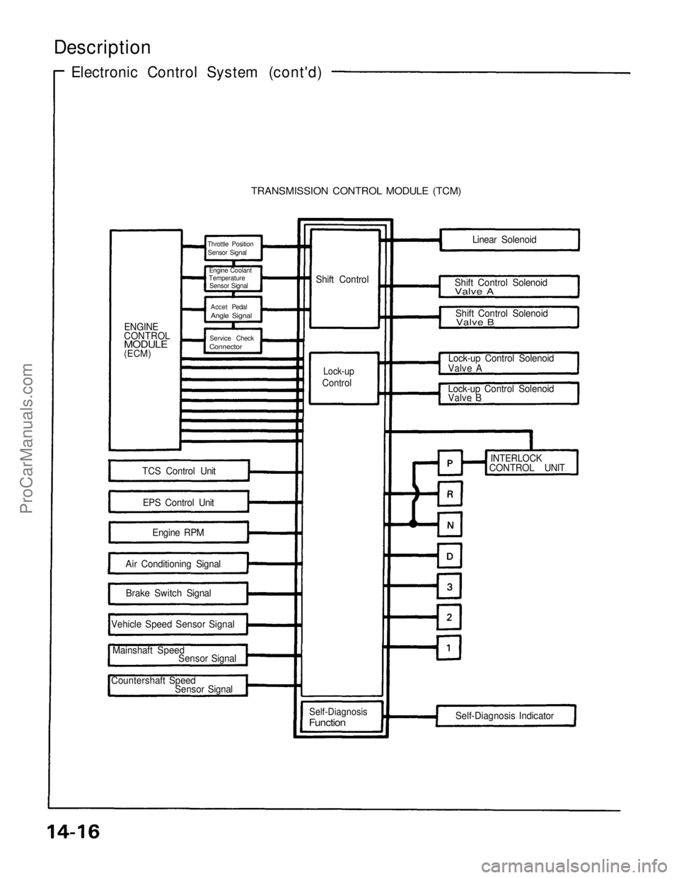
Description
Electronic Control System (cont'd)
TRANSMISSION CONTROL MODULE (TCM)
ENGINE
CONTROL
MODULE
(ECM) Shift Control
Lock-up
Control
TCS Control Unit
EPS Control Unit Engine RPM
Air Conditioning Signal Brake Switch Signal
Vehicle Speed Sensor Signal
Mainshaft Speed Sensor Signal
Countershaft Speed Sensor Signal
Self-Diagnosis
Function
Self-Diagnosis Indicator
INTERLOCK
CONTROL UNIT
Lock-up Control Solenoid
Valve B
Lock-up Control Solenoid
Valve A Shift Control Solenoid
Valve B
Shift Control Solenoid
Valve A
Linear Solenoid
Throttle Position
Sensor Signal
Engine Coolant
Temperature
Sensor Signal
Accet Pedal
Angle Signal
Service Check
Connector
ProCarManuals.com
Page 1190 of 1640
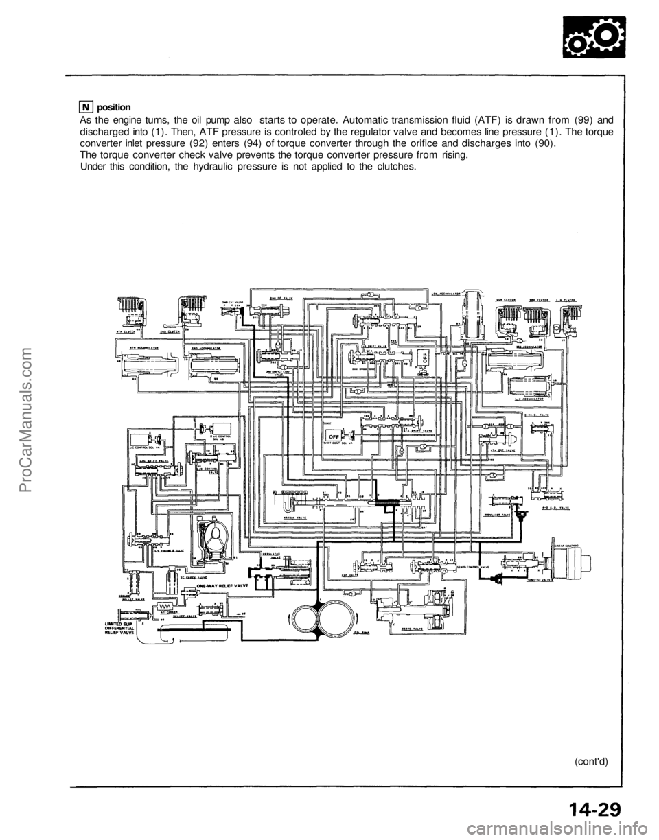
As the engine turns, the oil pump also starts to operate. Automatic transmission fluid (ATF) is drawn from (99) and
discharged into (1). Then, ATF pressure is controled by the regulator valve and becomes line pressure (1). The torque
converter inlet pressure (92) enters (94) of torque converter through the orifice and discharges into (90).
The torque converter check valve prevents the torque converter pressure from rising.
Under this condition, the hydraulic pressure is not applied to the clutches.
(cont'd)
positionProCarManuals.com