1991 ACURA NSX check engine
[x] Cancel search: check enginePage 1210 of 1640
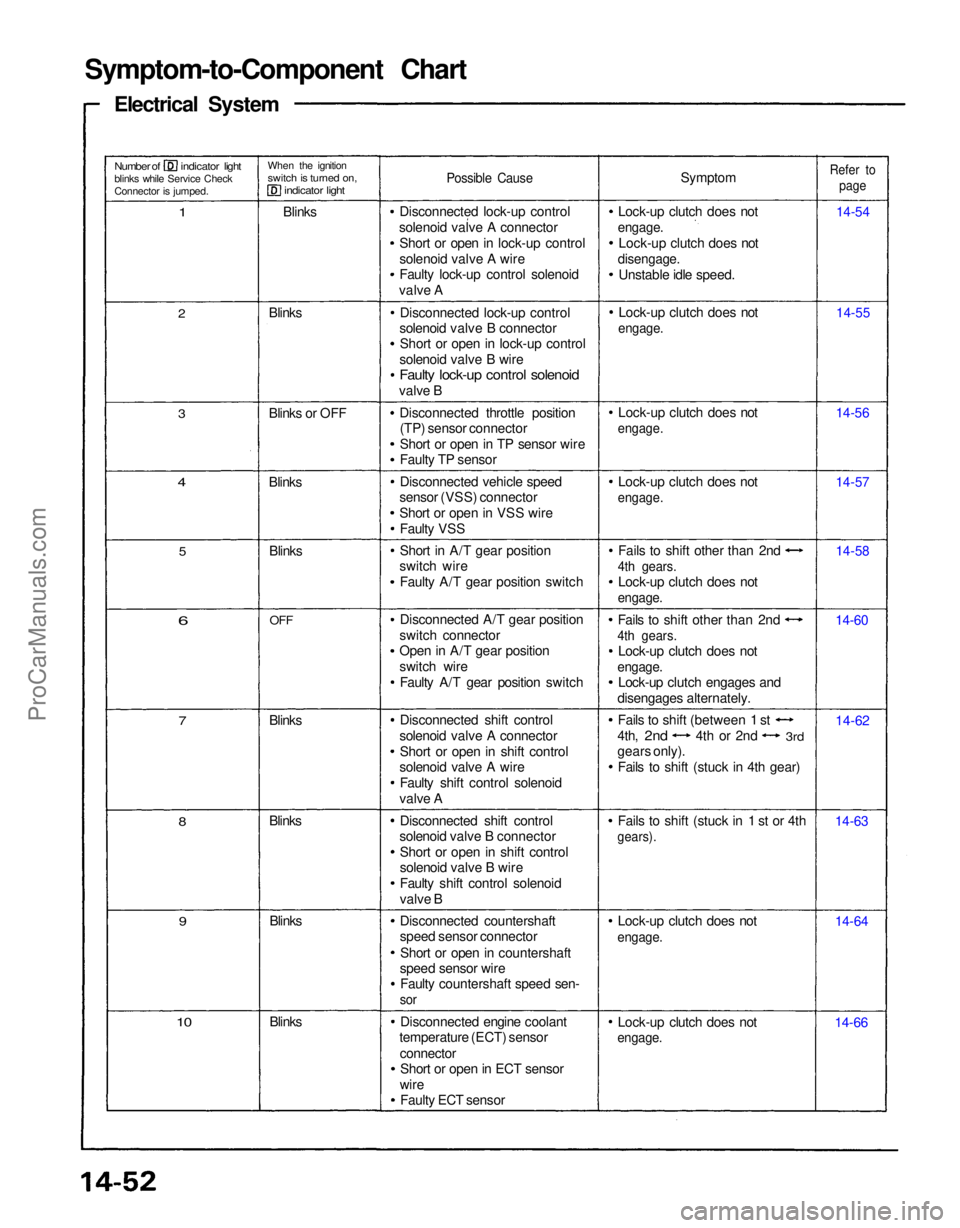
Symptom-to-Component Chart
Electrical System
Number of indicator light
blinks while Service Check
Connector is jumped.
When the ignition
switch is turned on,
indicator light
1
Blinks
Possible Cause
Symptom
Lock-up clutch does not
engage.
Lock-up clutch does not
disengage.
Unstable idle speed.
Refer to
page
14-54
14-55
14-56
14-57
14-58
14-60
14-62
14-63
14-64
14-66
Lock-up clutch does not
engage.
Lock-up clutch does not
engage.
Fails to shift (stuck in 1 st or 4th
gears).
Fails to shift other than 2nd
4th gears.
Lock-up clutch does not
engage.
Lock-up clutch engages and
disengages alternately. Fails to shift other than 2nd
4th gears.
Lock-up clutch does not
engage.
Lock-up clutch does not
engage.
Lock-up clutch does not
engage.
Lock-up clutch does not
engage.
Disconnected lock-up control
solenoid valve A connector Short or open in lock-up control
solenoid valve A wire
Faulty lock-up control solenoid
valve A
Disconnected lock-up control
solenoid valve B connector Short or open in lock-up control
solenoid valve B wire
Faulty lock-up control solenoid
valve B
Disconnected throttle position(TP) sensor connector
Short or open in TP sensor wire
Faulty TP sensor
Disconnected vehicle speed
sensor (VSS) connector
Short or open in VSS wire
Faulty VSS
Short in A/T gear position
switch wire
Faulty A/T gear position switch
Disconnected A/T gear position
switch connector
Open in A/T gear position
switch wire Faulty A/T gear position switch
Disconnected shift control
solenoid valve A connector Short or open in shift control
solenoid valve A wire
Faulty shift control solenoid
valve A
Disconnected shift control
solenoid valve B connector
Short or open in shift control
solenoid valve B wire
Faulty shift control solenoid
valve B
Disconnected countershaft
speed sensor connector
Short or open in countershaft
speed sensor wire Faulty countershaft speed sen-
sor
Disconnected engine coolant
temperature (ECT) sensor
connectorShort or open in ECT sensor
wire Faulty ECT sensor
Blinks
10
9
Blinks
Blinks
8
7
Blinks
6
OFF
Blinks
5
4
Blinks
3
Blinks or OFF Blinks
2
Fails to shift (between 1 st
4th,
2nd
4th or 2nd
3rd
gears only).
Fails to shift (stuck in 4th gear)ProCarManuals.com
Page 1211 of 1640
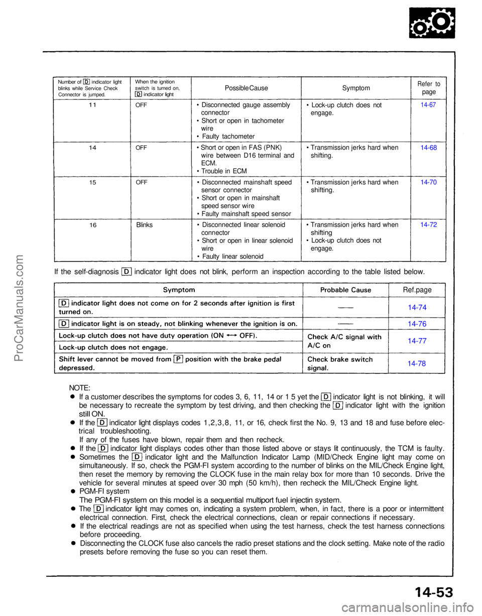
If a customer describes the symptoms for codes 3, 6, 11, 14 or 1 5 yet the indicator light is not blinking, it will
be necessary to recreate the symptom by test driving, and then checking the indicator light with the ignition
still
ON.
If the indicator light displays codes 1,2,3,8, 11, or 16, check first the No. 9, 13 and 18 and fuse before elec-
trical troubleshooting.
If any of the fuses have blown, repair them and then recheck. If the indicator light displays codes other than those listed above or stays lit continuously, the TCM is faulty.
Sometimes the indicator light and the Malfunction Indicator Lamp (MID/Check Engine light may come on
simultaneously. If so, check the PGM-FI system according to the number of blinks on the MIL/Check Engine light,
then reset the memory by removing the CLOCK fuse in the main relay box for more than 10 seconds. Drive the vehicle for several minutes at speed over 30 mph (50 km/h), then recheck the MIL/Check Engine light.PGM-FI system
The PGM-FI system on this model is a sequential multiport fuel injectin system.
The indicator light may comes on, indicating a system problem, when, in fact, there is a poor or intermittent
electrical connection. First, check the electrical connections, clean or repair connections if necessary.If the electrical readings are not as specified when using the test harness, check the test harness connections
before proceeding.
Disconnecting the CLOCK fuse also cancels the radio preset stations and the clock setting. Make note of the radio
presets before removing the fuse so you can reset them. If the self-diagnosis indicator light does not blink, perform an inspection according to the table listed below.
Symptom
• Lock-up clutch does not
engage.
• Transmission jerks hard when shifting.
• Transmission jerks hard when
shifting.
• Transmission jerks hard when
shifting
• Lock-up clutch does not
engage.
14-7214-70 14-68
14-67
Refer to
page
Possible Cause
• Disconnected gauge assembly connector
• Short or open in tachometer wire
• Faulty tachometer
• Short or open in FAS (PNK) wire between D16 terminal and
ECM.
• Trouble in ECM
• Disconnected mainshaft speed sensor connector
• Short or open in mainshaft speed sensor wire
• Faulty mainshaft speed sensor
• Disconnected linear solenoid connector
• Short or open in linear solenoid wire
• Faulty linear solenoid
Blinks
OFF
OFF
OFF
When the ignition
switch is turned on,
indicator light
Number of indicator light
blinks while Service CheckConnector is jumped.
11
14
15
16
Ref.page
14-74
14-76
14-77
14-78
NOTE:ProCarManuals.com
Page 1221 of 1640
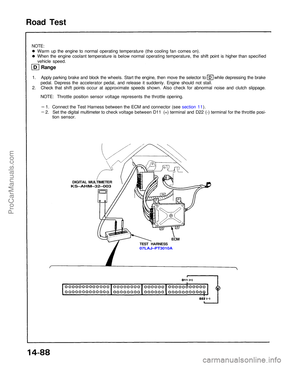
Road Test
NOTE:
Warm up the engine to normal operating temperature (the cooling fan comes on).
When the engine coolant temperature is below normal operating temperature, the shift point is higher than specifiedvehicle speed.
Range 1. Apply parking brake and block the wheels. Start the engine, then move the selector to while depressing the brake
pedal. Depress the accelerator pedal, and release it suddenly. Engine should not stall.
2. Check that shift points occur at approximate speeds shown. Also check for abnormal noise and clutch slippage.
NOTE: Throttle position sensor voltage represents the throttle opening.
DIGITAL MULTIMETER
KS–AHM–32–003
ECM
TEST HARNESS
07LAJ–PT3010A
1. Connect the Test Harness between the ECM and connector (see section 11).
2. Set the digital multimeter to check voltage between D11 (+) terminal and D22 (-) terminal for the throttle posi- tion sensor.ProCarManuals.com
Page 1222 of 1640
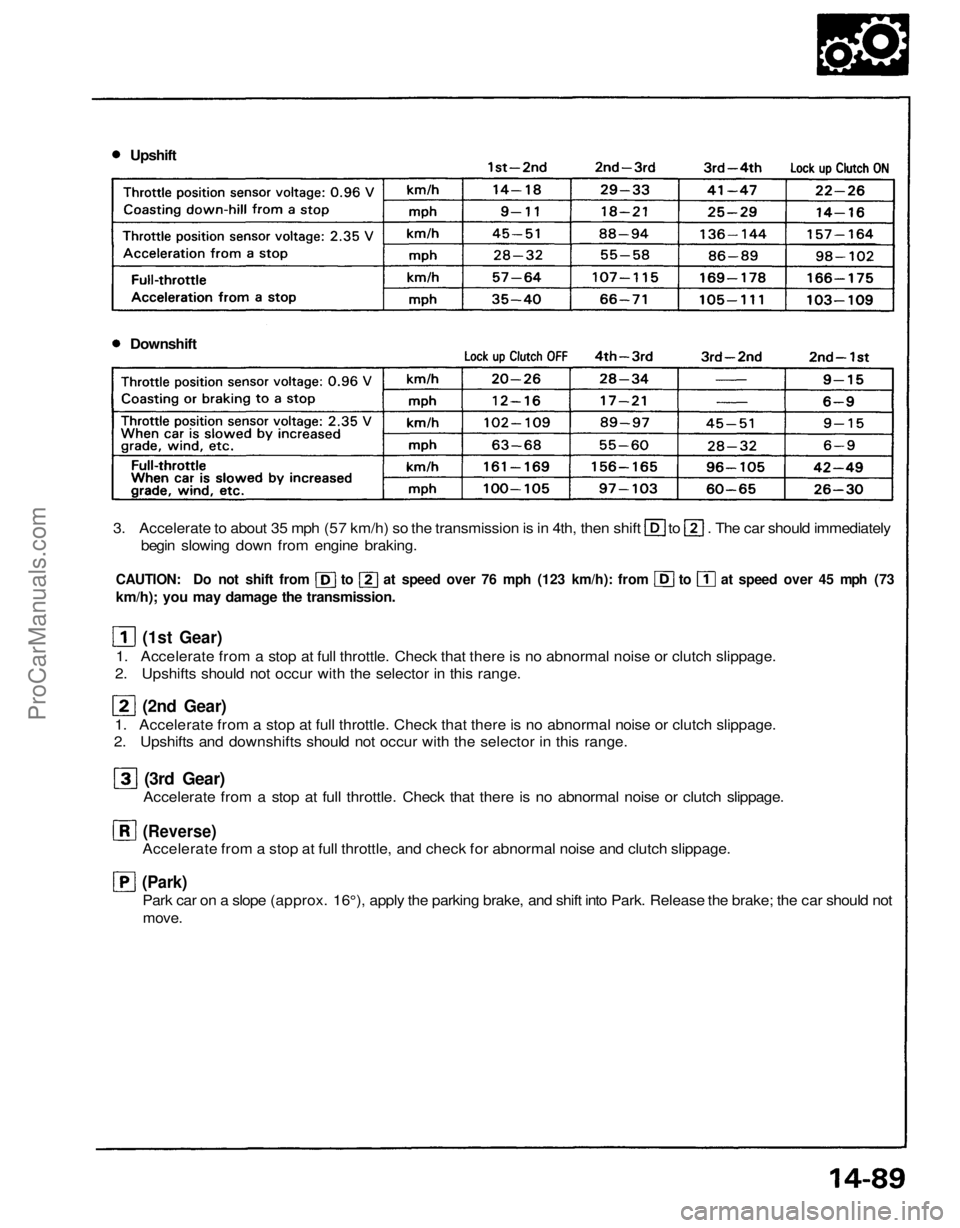
Upshift
Downshift
3. Accelerate to about 35 mph (57 km/h) so the transmission is in 4th, then shift to . The car should immediately
begin slowing down from engine braking.
CAUTION: Do not shift from to at speed over 76 mph (123 km/h): from to at speed over 45 mph (73
km/h); you may damage the transmission.
(1st Gear)
1. Accelerate from a stop at full throttle. Check that there is no abnormal noise or clutch slippage.
2. Upshifts should not occur with the selector in this range.
(2nd Gear)
1. Accelerate from a stop at full throttle. Check that there is no abnormal noise or clutch slippage.
2. Upshifts and downshifts should not occur with the selector in this range.
(3rd Gear)
Accelerate from a stop at full throttle. Check that there is no abnormal noise or clutch slippage.
(Reverse)
Accelerate from a stop at full throttle, and check for abnormal noise and clutch slippage.
(Park)
Park car on a slope (approx. 16°), apply the parking brake, and shift into Park. Release the brake; the car should not
move.ProCarManuals.com
Page 1224 of 1640
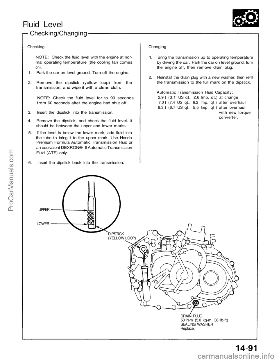
Fluid Level
Checking/Changing
Checking
NOTE: Check the fluid level with the engine at nor-
mal operating temperature (the cooling fan comes
on).
1. Park the car on level ground. Turn off the engine.
2. Remove the dipstick (yellow loop) from the
transmission, and wipe it with a clean cloth.
NOTE: Check the fluid level for to 90 seconds
from 60 seconds after the engine had shut off.
3. Insert the dipstick into the transmission.
4. Remove the dipstick, and check the fluid level. It
should be between the upper and lower marks.
5. If the level is below the lower mark, add fluid into
the tube to bring it to the upper mark. Use Honda
Premium Formula Automatic Transmission Fluid or
an equivalent DEXRON® II Automatic Transmission
Fluid (ATF) only.
6. Insert the dipstick back into the transmission.
UPPER
LOWER
DIPSTICK
(YELLOW LOOP)
DRAIN PLUG
50 N·m (5.0 kg-m, 36 Ib-ft)
SEALING WASHER
Replace.
Changing
1. Bring the transmission up to operating temperature
by driving the car. Park the car on level ground, turn
the engine off, then remove drain plug.
2. Reinstall the drain plug with a new washer, then refill
the transmission to the full mark on the dipstick.
Automatic Transmission Fluid Capacity:
2.9 (3.1 US qt., 2.6 Imp. qt.) at change
7.0 (7.4 US qt., 6.2 Imp. qt.) after overhaul
6.3 (6.7 US qt., 5.5 Imp. qt.) after overhaul
with new torque
converter.ProCarManuals.com
Page 1286 of 1640
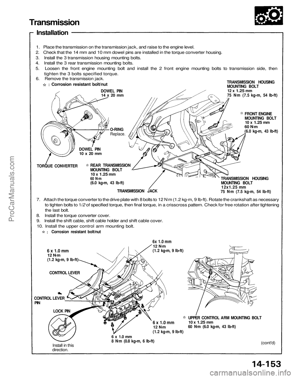
Transmission
Installation
1. Place the transmission on the transmission jack, and raise to the engine level.
2. Check that the 14 mm and 10 mm dowel pins are installed in the torque converter housing.
3. Install the 3 transmission housing mounting bolts.
4. Install the 3 rear transmission mounting bolts.
5. Loosen the front engine mounting bolt and install the 2 front engine mounting bolts to transmission side, then
tighten the 3 bolts specified torque.
TRANSMISSION HOUSINGMOUNTING BOLT
12 x
1.25
mm
75 N .
m (7.5 kg-m, 54 Ib-ft)
DOWEL PIN
14 x 20 mm
FRONT ENGINE
MOUNTING BOLT
10 x
1.25
mm
60 N .
m
(6.0 kg-m, 43 Ib-ft)
TRANSMISSION HOUSING MOUNTING BOLT
12x1.25 mm
75 N .
m (7.5 kg-m, 54 Ib-ft)
O-RING
Replace.
DOWEL PIN
10 x 20 mm
TORQUE CONVERTER REAR TRANSMISSION
MOUNTING BOLT
10 x
1.25
mm
60 N·m
(6.0 kg-m, 43 Ib-ft)
TRANSMISSION JACK
7. Attach the torque converter to the drive plate with 8 bolts to 12 N.m (1.2 kg-m, 9 Ib-ft). Rotate the crankshaft as necessary to tighten bolts to 1/2 of specified torque, then final torque, in a crisscross pattern. Check for free rotation after tighteningthe last bolt.
8. Install the torque converter cover. 9. Install the shift cable, shift cable holder and shift cable cover.
10. Install the upper control arm mounting bolt.
6x 1.0 mm
12 N
.
m
(1.2 kg-m, 9 Ib-ft)
6 x 1.0 mm
12 N
.
m
(1.2 kg-m, 9 Ib-ft)
CONTROL LEVER
UPPER CONTROL ARM MOUNTING BOLT
10 x
1.25
mm
60 N .
m (6.0 kg-m, 43 Ib-ft)
6 x 1.0 mm
12 N
.
m
(1.2 kg-m, 9 Ib-ft)
(cont'd)
6 x 1.0 mm
8 N
.
m (0.8 kg-m, 6 Ib-ft)
Install in this
direction.
LOCK PIN
CONTROL LEVER
PIN
Corrosion resistant bolt/nut
Corrosion resistant bolt/nut
6. Remove the transmission jack.ProCarManuals.com
Page 1289 of 1640
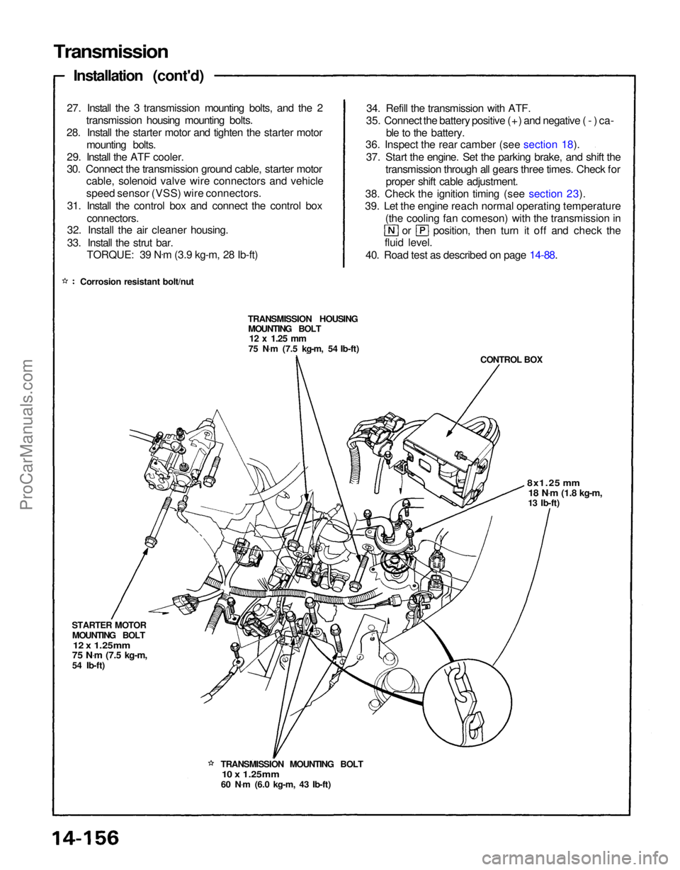
Transmission
Installation (cont'd)
27. Install the 3 transmission mounting bolts, and the 2 transmission housing mounting bolts.
28. Install the starter motor and tighten the starter motor mounting bolts.
29. Install the ATF cooler.
30. Connect the transmission ground cable, starter motor cable, solenoid valve wire connectors and vehicle
speed sensor (VSS) wire connectors.
31. Install the control box and connect the control box connectors.
32. Install the air cleaner housing.
33. Install the strut bar.
TORQUE: 39 N .
m (3.9 kg-m, 28 Ib-ft)
Corrosion resistant bolt/nut 34. Refill the transmission with ATF.
35. Connect the battery positive (+) and negative (-) ca- ble to the battery.
36. Inspect the rear camber (see section 18).
37. Start the engine. Set the parking brake, and shift the transmission through all gears three times. Check forproper shift cable adjustment.
38. Check the ignition timing (see section 23).
39. Let the engine reach normal operating temperature (the cooling fan comeson) with the transmission in or position, then turn it off and check the
fluid level.
40. Road test as described on page 14-88.
TRANSMISSION HOUSING MOUNTING BOLT
12 x
1.25
mm
75 N .
m (7.5 kg-m, 54 Ib-ft)
CONTROL BOX
8x1.25 mm
18 N .
m
(1.8 kg-m,
13 Ib-ft)
TRANSMISSION MOUNTING BOLT
10 x 1.25mm
60 N .
m (6.0 kg-m, 43 Ib-ft)
STARTER MOTOR
MOUNTING BOLT
12 x 1.25mm
75 N .
m
(7.5 kg-m,
54 Ib-ft)ProCarManuals.com
Page 1290 of 1640
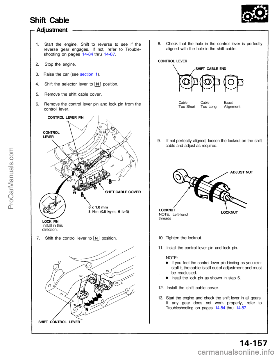
Shift Cable
Adjustment
1. Start the engine. Shift to reverse to see if the reverse gear engages. If not, refer to Trouble-
shooting on pages 14-84 thru 14-87.
2. Stop the engine. 3. Raise the car (see section 1). 4. Shift the selector lever to position.
5. Remove the shift cable cover.
6. Remove the control lever pin and lock pin from the control lever.
CONTROL LEVER PIN
CONTROL
LEVER
SHIFT CABLE COVER
6 x 1.0 mm
8 N .
m (0.8 kg-m, 6 Ib-ft)
LOCK PIN Install in this
direction.
7. Shift the control lever to position.
SHIFT CONTROL LEVER 12. Install the shift cable cover.
13. Start the engine and check the shift lever in all gears. If any gear does not work properly, refer to
Troubleshooting on pages 14-84 thru 14-87. If you feel the control lever pin binding as you rein-
stall it, the cable is still out of adjustment and must
be readjusted.
Install the lock pin as shown in step 6.
10. Tighten the locknut.
11. Install the control lever pin and lock pin.
NOTE:
LOCKNUT
LOCKNUT
NOTE: Left-hand
threads
ADJUST NUT
9. If not perfectly aligned, loosen the locknut on the shift
cable and adjust as required. Cable Cable Exact
Too Short Too Long Alignment
SHIFT CABLE END
CONTROL LEVER
8. Check that the hole in the control lever is perfectly
aligned with the hole in the shift cable.ProCarManuals.com