Page 1298 of 1640
Inspection
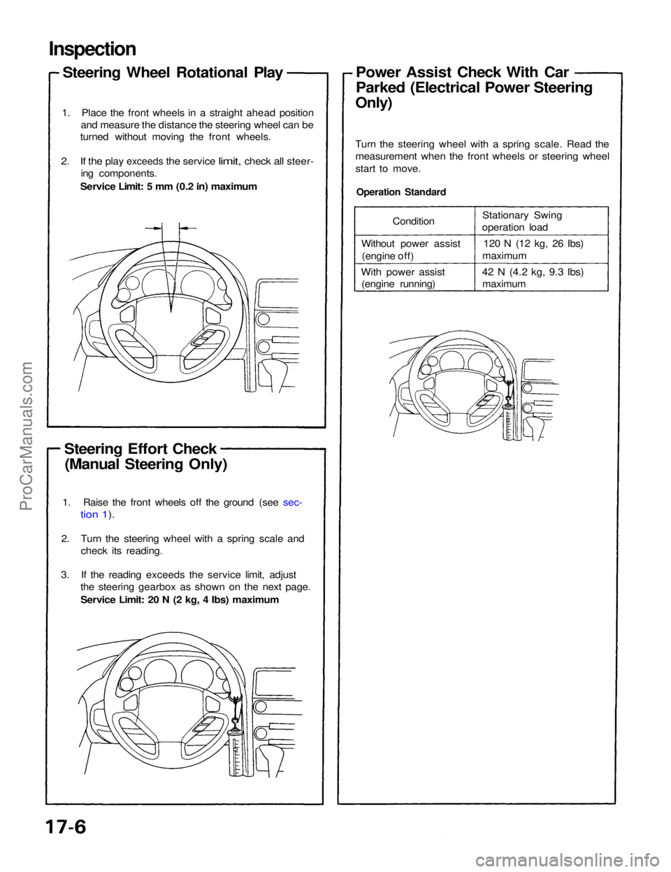
Steering Wheel Rotational Play
1. Place the front wheels in a straight ahead position and measure the distance the steering wheel can be
turned without moving the front wheels.
2. If the
play
exceeds
the
service
limit,
check
all
steer- ing components.
Service Limit: 5 mm (0.2 in) maximum
Steering Effort Check (Manual Steering Only)
Operation Standard
Turn the steering wheel with a spring scale. Read the
measurement when the front wheels or steering wheel
start to move.Power Assist Check With Car
Parked (Electrical Power Steering
Only)
1. Raise the front wheels off the ground (see sec-
tion 1).
2. Turn the steering wheel with a spring scale and check its reading.
3. If the reading exceeds the service limit, adjust the steering gearbox as shown on the next page.
Service Limit: 20 N (2 kg, 4 Ibs) maximum Condition
Without power assist (engine off)
With power assist (engine running) Stationary Swing
operation load
120 N (12 kg, 26
Ibs)
maximum
42 N
(4.2
kg, 9.3
Ibs) maximumProCarManuals.com
Page 1335 of 1640
Troubleshooting Procedures
Under normal conditions, the EPS indicator light in the gauge assembly comes on when the ignition switch is turned
to the ON position, then goes off after the engine is started. This indicates that the bulb and its circuits are operating
correctly.
EPS INDICATOR LIGHT
When the EPS control unit senses an abnormality in the system, the control unit memorizes the problem, the EPS indica-
tor light blinks at equal intervals, and the power steering assist is turned off.
When the EPS indicator light has been reported on, connect the two terminals of the service check connector with a
jumper wire. Then turn on the ignition switch and observe the blinking frequency.
SERVICE CHECK
CONNECTOR (BLU)
GRN/WHT
SERVICE CHECK CONNECTOR (BLU)
BLUProCarManuals.com
Page 1365 of 1640
Troubleshooting
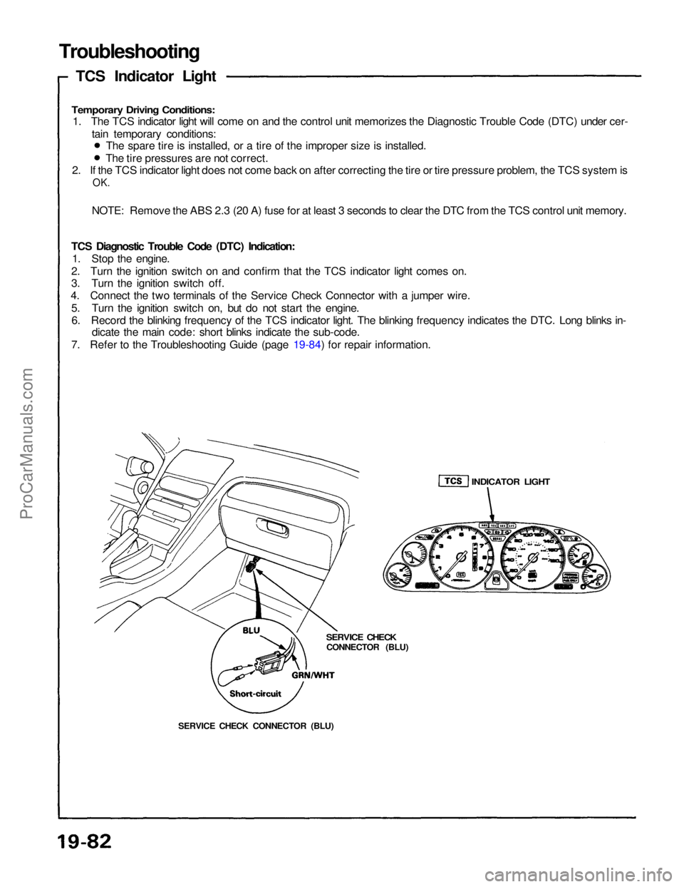
TCS Indicator Light
Temporary Driving Conditions:
1. The TCS indicator light will come on and the control unit memorizes the Diagnostic Trouble Code (DTC) under cer-
tain temporary conditions:
2. If the TCS indicator light does not come back on after correcting the tire or tire pressure problem, the TCS system is
OK.
NOTE: Remove the ABS 2.3 (20 A) fuse for at least 3 seconds to clear the DTC from the TCS control unit memory.
TCS Diagnostic Trouble Code (DTC) Indication: 1. Stop the engine.
2. Turn the ignition switch on and confirm that the TCS indicator light comes on.
3. Turn the ignition switch off.
4. Connect the two terminals of the Service Check Connector with a jumper wire.
5. Turn the ignition switch on, but do not start the engine.6. Record the blinking frequency of the TCS indicator light. The blinking frequency indicates the DTC. Long blinks in- dicate the main code: short blinks indicate the sub-code.
7. Refer to the Troubleshooting Guide (page 19-84) for repair information. The spare tire is installed, or a tire of the improper size is installed.
The tire pressures are not correct.
SERVICE CHECK CONNECTOR (BLU)
SERVICE CHECK
CONNECTOR (BLU)
INDICATOR LIGHTProCarManuals.com
Page 1366 of 1640
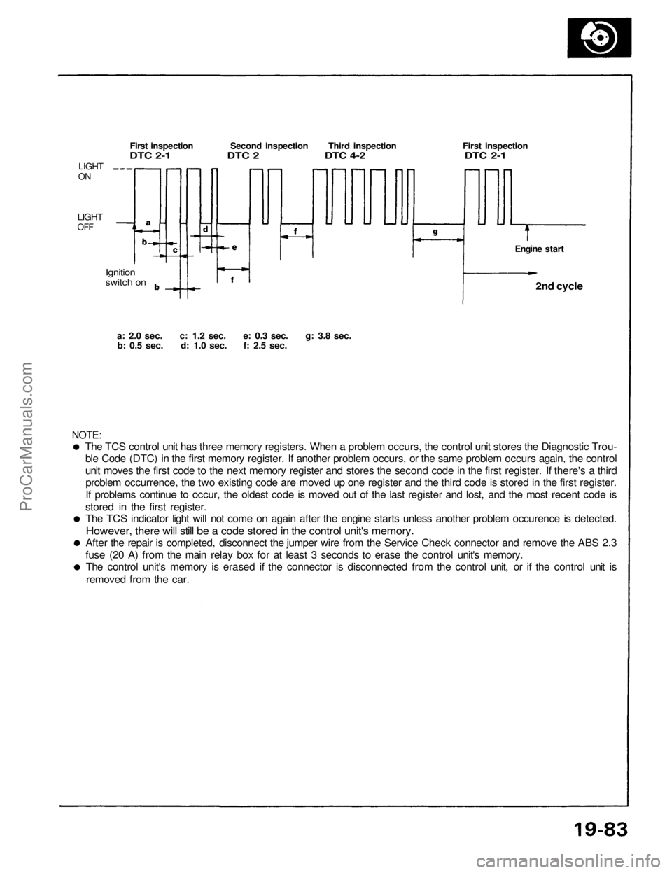
The TCS control unit has three memory registers. When a problem occurs, the control unit stores the Diagnostic Trou-
ble Code (DTC) in the first memory register. If another problem occurs, or the same problem occurs again, the control
unit moves the first code to the next memory register and stores the second code in the first register. If there's a thirdproblem occurrence, the two existing code are moved up one register and the third code is stored in the first register.
If problems continue to occur, the oldest code is moved out of the last register and lost, and the most recent code is
stored in the first register. The TCS indicator light will not come on again after the engine starts unless another problem occurence is detected.
However, there will still be a code stored in the control unit's memory.
After the repair is completed, disconnect the jumper wire from the Service Check connector and remove the ABS 2.3
fuse (20 A) from the main relay box for at least 3 seconds to erase the control unit's memory. The control unit's memory is erased if the connector is disconnected from the control unit, or if the control unit is
removed from the car.
NOTE:
a: 2.0
sec.
c: 1.2
sec.
e: 0.3
sec.
g: 3.8
sec.
b: 0.5
sec.
d: 1.0
sec.
f: 2.5
sec.
Ignition
switch on
LIGHT
ON
LIGHT
OFF
First inspection Second inspection Third inspection First inspection
DTC 2-1 DTC 2 DTC 4-2 DTC 2-1
Engine start2nd cycle
ProCarManuals.com
Page 1393 of 1640
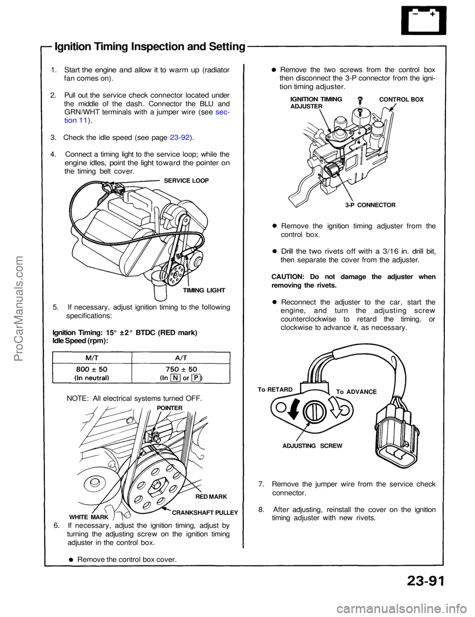
Ignition Timing Inspection and Setting
1. Start the engine and allow it to warm up (radiator
fan comes on).
2. Pull out the service check connector located under the middle of the dash. Connector the BLU andGRN/WHT terminals with a jumper wire (see sec-
tion 11).
3. Check the idle speed (see page 23-92).
4. Connect a timing light to the service loop; while the
engine idles, point the light toward the pointer on
the timing belt cover.
SERVICE LOOP
TIMING LIGHT
5. If necessary, adjust ignition timing to the following specifications:
Ignition Timing: 15° ±2° BTDC (RED mark)
Idle Speed (rpm):
NOTE: All electrical systems turned OFF. POINTER
RED MARK
CRANKSHAFT PULLEY
WHITE MARK
6. If necessary, adjust the ignition timing, adjust by turning the adjusting screw on the ignition timingadjuster in the control box.
Remove the control box cover. 7. Remove the jumper wire from the service check
connector.
8. After adjusting, reinstall the cover on the ignition timing adjuster with new rivets.ADJUSTING SCREW
To ADVANCE
To RETARD Reconnect the adjuster to the car, start the
engine, and turn the adjusting screw
counterclockwise to retard the timing, or
clockwise to advance it, as necessary.
CAUTION: Do not damage the adjuster when
removing the rivets. Remove the ignition timing adjuster from the
control box.
Drill the two rivets off with a 3/16 in. drill bit,
then separate the cover from the adjuster. 3-P CONNECTORCONTROL BOX
IGNITION TIMING
ADJUSTER
Remove the two screws from the control box
then disconnect the 3-P connector from the igni-
tion timing adjuster.ProCarManuals.com
Page 1448 of 1640
Actuator Cable Adjustment
1. Check that the actuator cable moves smoothly
with no binding or sticking.
2. Start the engine and warm it up to normal operating temperature (radiator fan comes on).
3. Measure how far the output linkage moves before the engine speed starts to increase.
Make sure you begin with the linkage at the fully
closed position. Free play should be 11 ± 1.5 mm (0.43
±
0.06 in).
OUTPUT
LINKAGE
ADJUSTING NUT
ACTUATOR
CABLE
LOCKNUT
FREE PLAY:
11 ± 1.5 mm
(0.43
±
0.06
in)
FULLY CLOSED POSITION
4. If the free play is not within specs, loosen the lock- nut and turn the adjusting nut as required.
NOTE: If necessary, check the throttle control
system (see section 11), then recheck the output
linkage free play.
5. Retighten the locknut and recheck the free play.ProCarManuals.com
Page 1462 of 1640
Oil Level
Engine Oil
Inspection
Replacement
1. Check engine oil with the engine off and the car parked on level ground.
2. Make certain that the oil level indicated on the dipstick is between the upper and lower marks.
3. If the level has dropped close to the lower mark, add oil until it reaches the upper mark.
CAUTION: Insert the dipstick carefully to avoid
bending it.
1. Warm up the engine.
2. Drain the engine oil.
WASHER
Replace.
OIL PAN DRAIN PLUG
45 N·m (4.5 kg-m, 33 Ib-ft)
DIPSTICK
UPPER
LOWER
3. Reinstall the drain plug with a new washer, and
refill with the recommended oil.
Engine Oil Viscosity for Outside Temperature Ranges.
NOTE: Oil filter should be replaced at each oil
change.ProCarManuals.com
Page 1477 of 1640
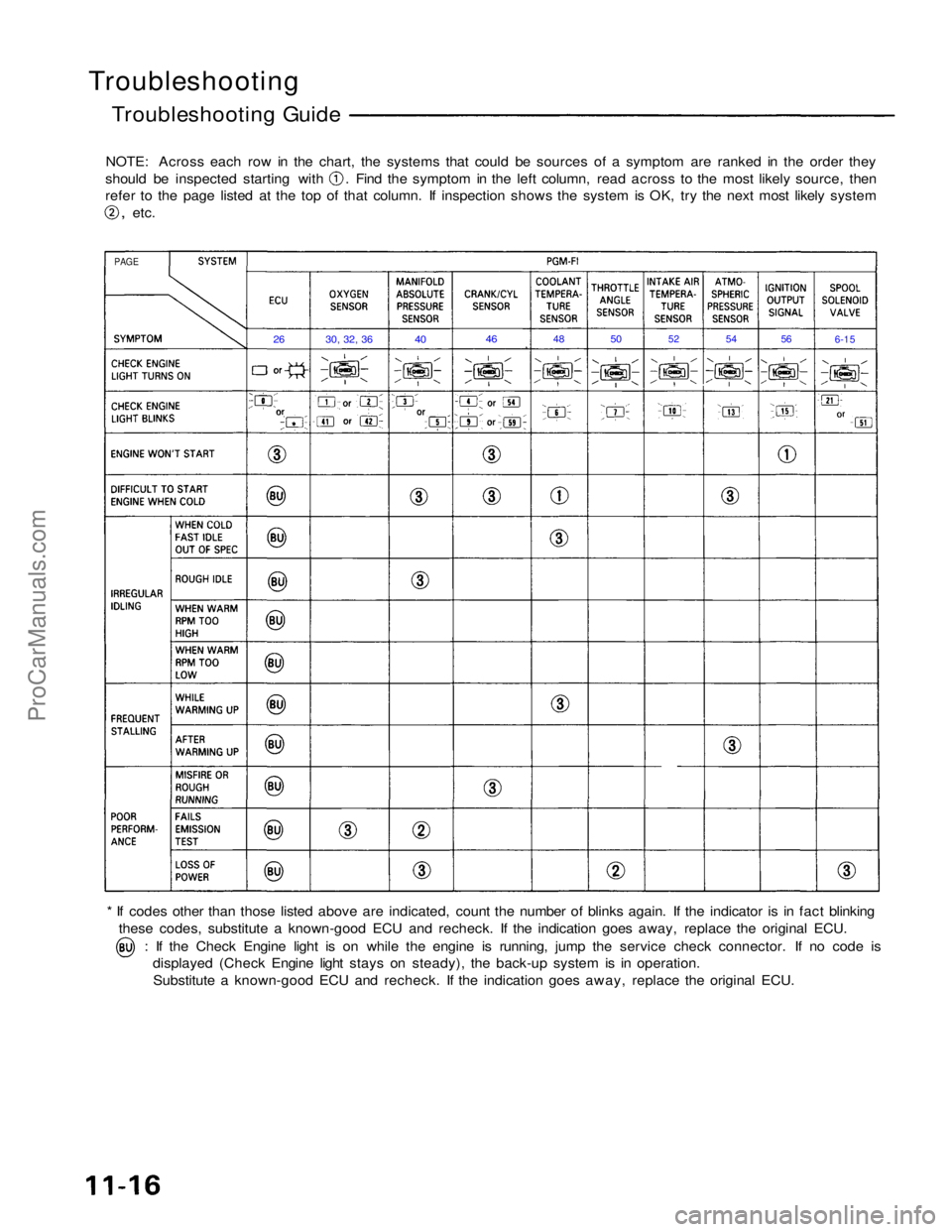
Troubleshooting
Troubleshooting Guide
NOTE: Across each row in the chart, the systems that could be sources of a symptom are ranked in the order they should be inspected starting with . Find the symptom in the left column, read across to the most likely source, then
refer to the page listed at the top of that column. If inspection shows the system is OK, try the next most likely system
,
etc.
* If codes other than those listed above are indicated, count the number of blinks again. If the indicator is in fact blinking these codes, substitute a known-good ECU and recheck. If the indication goes away, replace the original ECU. : If the Check Engine light is on while the engine is running, jump the service check connector. If no code is
displayed (Check Engine light stays on steady), the back-up system is in operation.
Substitute a known-good ECU and recheck. If the indication goes away, replace the original ECU.
PAGE
26
30, 32, 36
40
46
48
50
52
54
56
6-15ProCarManuals.com