Page 1490 of 1640
(From page 11-74)
Disconnect "D" connector from
ECU only, not the engine wire
harness.
Disconnect the negative battery
cable from the battery.
Check for continuity between D9
terminal and body ground.
Continuity ?
Disconnect GRN connector from
the alternator.
Disconnect GRN connector from
the alternator. GRN CONNECTOR
Connect WHT/RED wire to body
ground.
Check for continuity between D9
terminal and body ground.
Check for continuity between D9
terminal and body ground.
Does continuity exist ?
Does continuity exist ? See Alternator Inspec-
tion.
See Alternator Inspec-
tion.
Repair open in WHT/RED wire
between ECU (D9) and alter-
nator. Does continuity exist ?
Repair short in WHT/RED wire
between ECU (D9) and alter-
nator.ProCarManuals.com
Page 1491 of 1640
Idle Control System
Troubleshooting Flowchart
A/T Shift Position Signal
This signals the PGM-FI ECU when the transmission is in Neutral or Park.
Inspection of A/T Shift Position
Signal.
Turn the ignition switch ON.
Observe the A/T shift indicator and
select each position separately. See A/T Shift Position Indicator
Inspection.
Does the indicator light properly?
Turn the ignition switch OFF.
Connect the ECU test harness
between the ECU and connector. Disconnect "B" connector from
the engine wire harness only, not
the ECU (page 11-21).
10V
B7
A26
Turn the ignition switch ON.
Measure voltage between B7 ( + ) terminal and A26 (-) ter-
minal.
Is there approx. 10 V?
Substitute a known-good ECU
and recheck. If prescribed voltage
is now available, replace the
original ECU.
Turn the ignition switch OFF.
Reconnect "B" connector to the
engine wire harness.
Turn the ignition switch ON.
(To page 11-77)ProCarManuals.com
Page 1493 of 1640

Idle Control System
Troubleshooting Flowchart
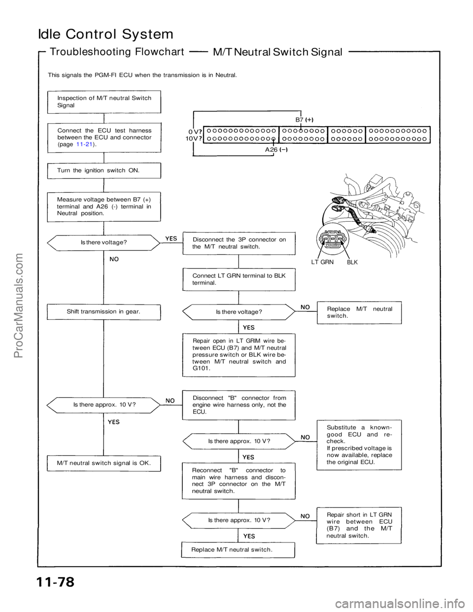
M/T Neutral Switch Signal
This signals the PGM-FI ECU when the transmission is in Neutral.
Inspection of M/T neutral Switch
Signal
Connect the ECU test harness
between the ECU and connector
(page 11-21).
0V
10V
B7
A26
Turn the ignition switch ON.
Measure voltage between B7 (+)
terminal and A26 (-) terminal in Neutral position.
Is there voltage? Disconnect the 3P connector on
the M/T neutral switch.
LT GRN
BLK
Connect LT GRN terminal to BLK
terminal.
Is there voltage?
Shift transmission in gear. Replace M/T neutral
switch.
Repair open in LT GRIM wire be-
tween ECU (B7) and M/T neutral
pressure switch or BLK wire be-
tween M/T neutral switch and G101.
Is there approx. 10 V? Disconnect "B" connector from
engine wire harness only, not the
ECU.
Is there approx. 10 V?
M/T neutral switch signal is OK. Substitute a known-
good ECU and re-
check.
If prescribed voltage is
now available, replace
the original ECU.
Reconnect "B" connector to
main wire harness and discon-
nect 3P connector on the M/T
neutral switch.
Is there approx. 10 V?
Repair short in LT GRN
wire between ECU
(B7)
and the M/T
neutral switch.
Replace M/T neutral switch.ProCarManuals.com
Page 1495 of 1640
(From page 11-80)
Is there approx. 10V?
Clutch switch signal is OK.
Turn the ignition switch OFF.
Disconnect the 3P connector
from the clutch switch.
Turn the ignition switch ON.
Measure voltage between C7 (+)
terminal and A26 (-) terminal with the clutch pedal depressed.
Is there approx. 10V? Replace the clutch
switch.
Turn the ignition switch OFF.
Disconnect "C" connector from
engine wire harness only, not the
ECU.
Turn the ignition switch ON.
Is there approx. 10V? Repair short in PNK
wire between ECU
(C7) and the clutch
switch.
Substitute a known-good ECU
and recheck. If prescribed
voltage is now available, replace
the original ECU.ProCarManuals.com
Page 1497 of 1640

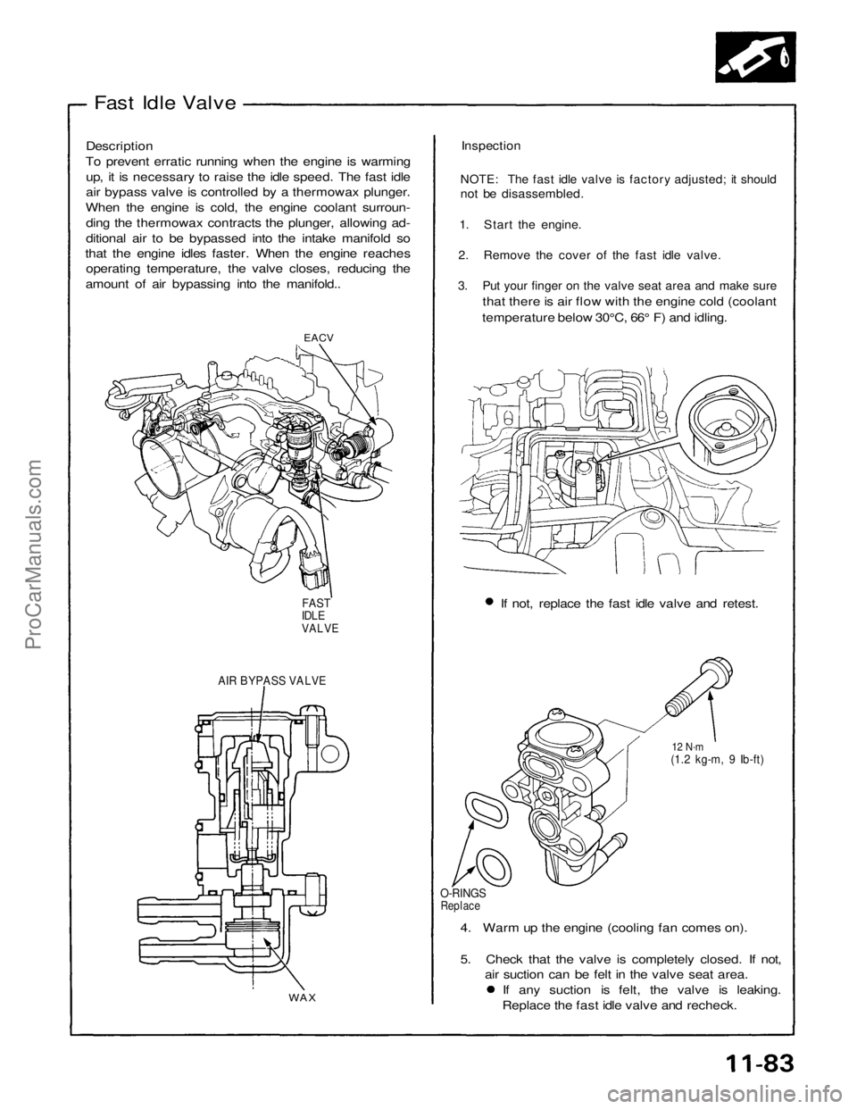
Fast Idle Valve
Description
To prevent erratic running when the engine is warming up, it is necessary to raise the idle speed. The fast idle
air bypass valve is controlled by a thermowax plunger.
When the engine is cold, the engine coolant surroun- ding the thermowax contracts the plunger, allowing ad-
ditional air to be bypassed into the intake manifold so
that the engine idles faster. When the engine reaches operating temperature, the valve closes, reducing the
amount of air bypassing into the manifold..
Inspection
NOTE: The fast idle valve is factory adjusted; it should
not be disassembled.
1. Start the engine.
2. Remove the cover of the fast idle valve.
3. Put your finger on the valve seat area and make sure
that there is air flow with the engine cold (coolant
temperature below 30°C, 66° F) and idling.
EACV
If not, replace the fast idle valve and retest.
FAST
IDLE
VALVE
AIR BYPASS VALVE
12 N·m
(1.2 kg-m, 9 Ib-ft)
O-RINGS
Replace
4. Warm up the engine (cooling fan comes on).
5. Check that the valve is completely closed. If not, air suction can be felt in the valve seat area. If any suction is felt, the valve is leaking.
Replace the fast idle valve and recheck.
WAXProCarManuals.com
Page 1498 of 1640

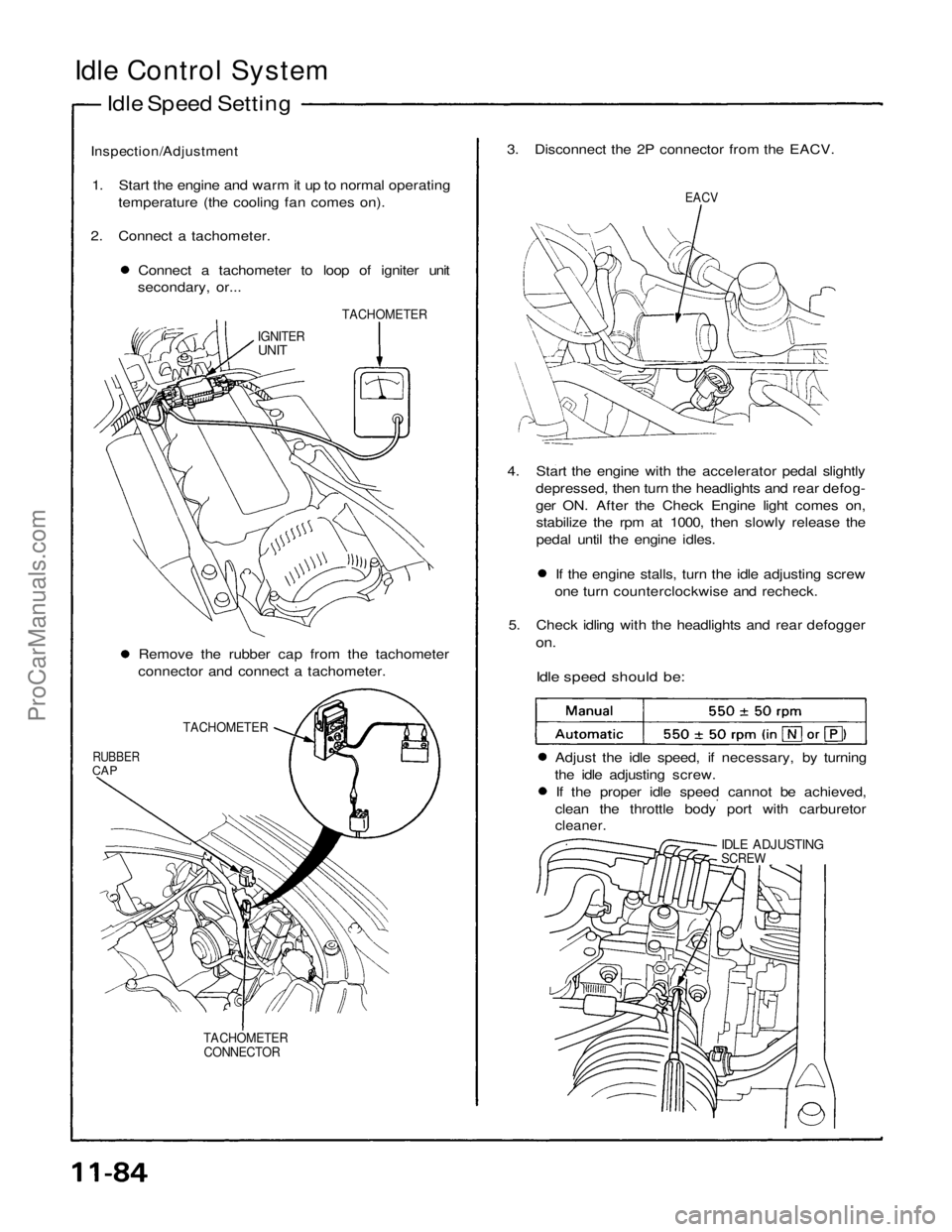
Idle Control System
Idle Speed Setting
Inspection/Adjustment
1. Start the engine and warm it up to normal operating temperature (the cooling fan comes on).
2. Connect a tachometer. Connect a tachometer to loop of igniter unit
secondary, or... 3. Disconnect the 2P connector from the EACV.
EACV
TACHOMETER
IGNITER
UNIT
4. Start the engine with the accelerator pedal slightlydepressed, then turn the headlights and rear defog-
ger ON. After the Check Engine light comes on,stabilize the rpm at 1000, then slowly release the
pedal until the engine idles. If the engine stalls, turn the idle adjusting screw
one turn counterclockwise and recheck.
5. Check idling with the headlights and rear defogger
on.
Idle speed should be:
Remove the rubber cap from the tachometer
connector and connect a tachometer.
TACHOMETER
RUBBER
CAP
Adjust the idle speed, if necessary, by turning
the idle adjusting screw. If the proper idle speed cannot be achieved,
clean the throttle body port with carburetor
cleaner.
IDLE ADJUSTING
SCREW
TACHOMETER CONNECTORProCarManuals.com
Page 1499 of 1640
6. Turn the ignition switch OFF.
7. Reconnect the 2P connector on the EACV, then
remove CLOCK fuse in the under-hood fuse/relay
box for 10 seconds to reset ECU.
8. Restart and idle the engine with no-load conditions
in which the headlights, blower fan, rear defogger,
cooling fan, and air conditioner are not operating
for one minute, then check the idle speed.
Idle speed should be:ProCarManuals.com
Page 1506 of 1640
Fuel Supply System
Pressure Regulator (cont'd)
3. Check that the fuel pressure rises when the vacuum hose from the regulator is disconnected again.
If the fuel pressure did not rise, check to see if it
rises with the fuel return hose lightly pinched.
If the fuel pressure still does not rise, replace the
pressure regulator.
Replacement
Do not smoke while working on fuel sys-
tem . Keep open flame away from work area.
1. Place a shop towel under pressure regulator, then
relieve fuel pressure (page
11-87).
2. Disconnect the vacuum hose and fuel return hose.
3. Remove the two 6 mm retainer bolts.
O-RING
Replace.
PRESSURE REGULATOR
RETURN HOSE
SHOP TOWEL
NOTE:
Replace the O-ring. When assembling the regulator, apply clean engine
oil to the O-ring and assemble it into its proper
position, taking care not to damage the O-ring.ProCarManuals.com