Page 1508 of 1640

Fuel Supply System
Fuel Pump
Description
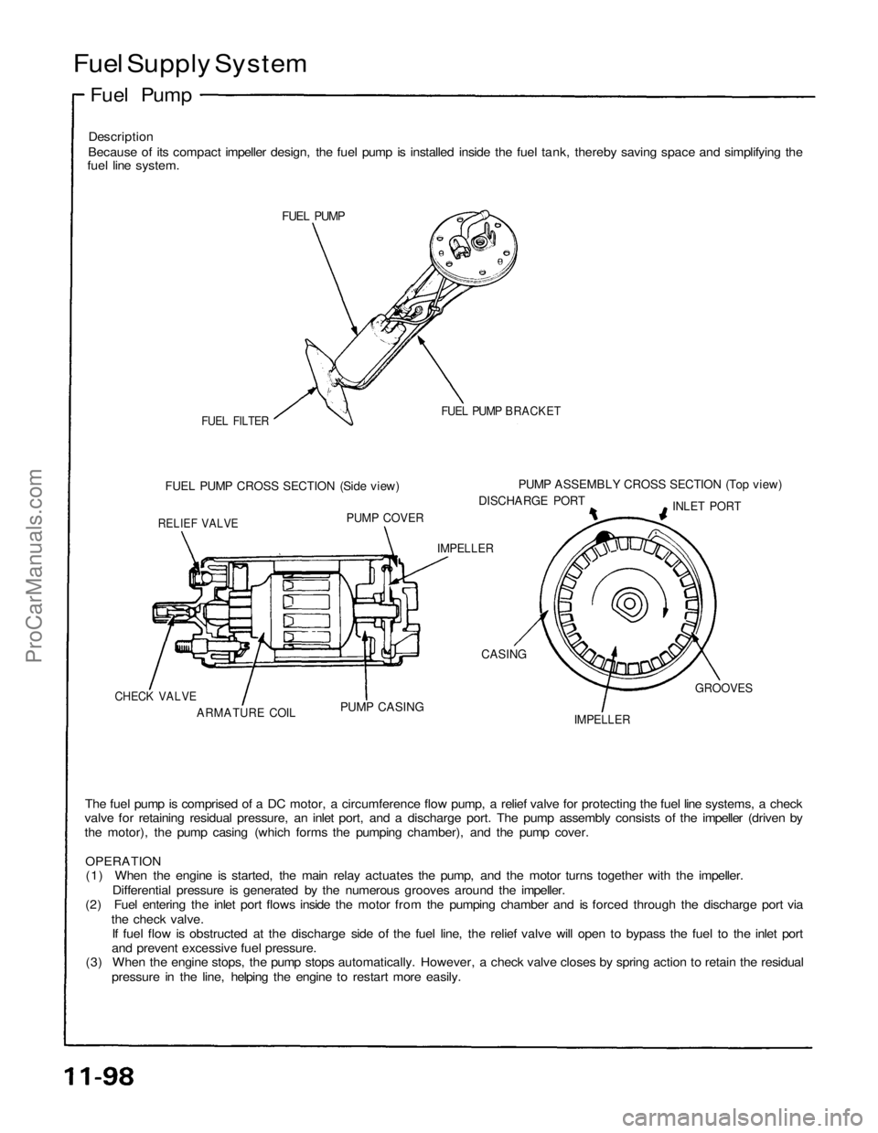
Because of its compact impeller design, the fuel pump is installed inside the fuel tank, thereby saving space and simplifying the
fuel line system.
FUEL PUMP
FUEL FILTER
FUEL PUMP BRACKET
FUEL PUMP CROSS SECTION (Side view)
PUMP ASSEMBLY CROSS SECTION (Top view)
DISCHARGE PORT
INLET PORT
RELIEF VALVE
PUMP COVER
IMPELLER
CASING
IMPELLER
GROOVES
PUMP CASING
ARMATURE COIL
CHECK VALVE
The fuel pump is comprised of a DC motor, a circumference flow pump, a relief valve for protecting the fuel line systems, a check
valve for retaining residual pressure, an inlet port, and a discharge port. The pump assembly consists of the impeller (driven by
the motor), the pump casing (which forms the pumping chamber), and the pump cover.
OPERATION
(1) When the engine is started, the main relay actuates the pump, and the motor turns together with the impeller.
Differential pressure is generated by the numerous grooves around the impeller.
(2) Fuel entering the inlet port flows inside the motor from the pumping chamber and is forced through the discharge port via
the check valve.
If fuel flow is obstructed at the discharge side of the fuel line, the relief valve will open to bypass the fuel to the inlet port
and prevent excessive fuel pressure.
(3) When the engine stops, the pump stops automatically. However, a check valve closes by spring action to retain the residual
pressure in the line, helping the engine to restart more easily.ProCarManuals.com
Page 1510 of 1640

Main Relay
Description
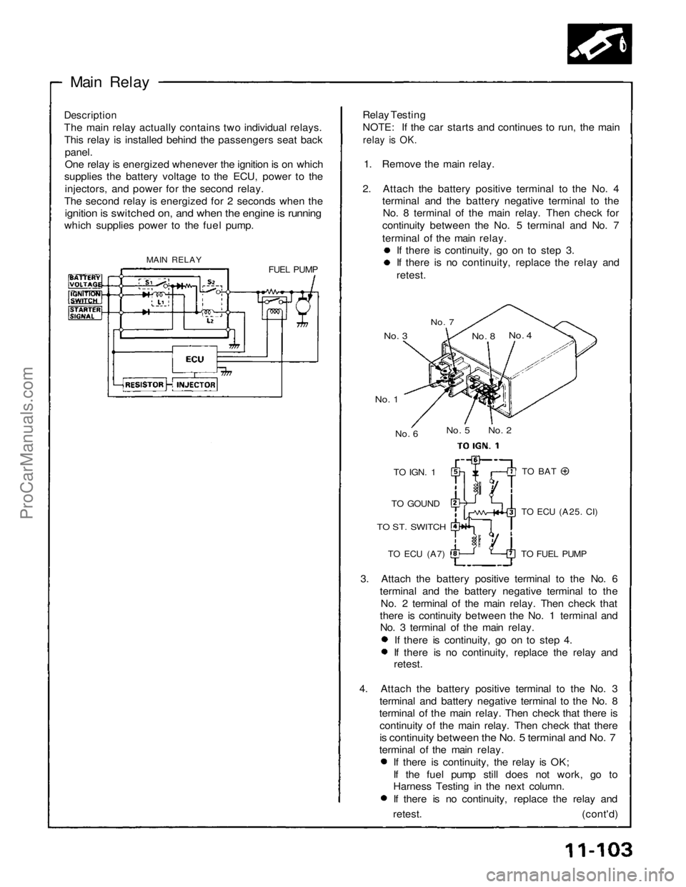
The main relay actually contains two individual relays. This relay is installed behind the passengers seat back
panel.
One relay is energized whenever the ignition is on which
supplies the battery voltage to the ECU, power to the
injectors, and power for the second relay.
The second relay is energized for 2 seconds when the
ignition is switched on, and when the engine is running
which supplies power to the fuel pump.
MAIN RELAY FUEL PUMPRelay Testing
NOTE: If the car starts and continues to run, the main
relay is OK.
1. Remove the main relay.
2. Attach the battery positive terminal to the No. 4 terminal and the battery negative terminal to theNo. 8 terminal of the main relay. Then check for
continuity between the No. 5 terminal and No. 7
terminal of the main relay. If there is continuity, go on to step 3. If there is no continuity, replace the relay and
retest.
No. 7
No. 3
No. 4
No. 8
No. 2
No. 5
No. 6
No. 1
TO
IGN.
1
TO GOUND
TO ST. SWITCH
TO ECU
(A7)
TO BAT
TO ECU
(A25.
CI)
TO FUEL PUMP
3. Attach the battery positive terminal to the No. 6 terminal and the battery negative terminal to theNo. 2 terminal of the main relay. Then check that
there is continuity between the No. 1 terminal and No. 3 terminal of the main relay.
If there is continuity, go on to step 4. If there is no continuity, replace the relay and
retest.
4. Attach the battery positive terminal to the No. 3 terminal and battery negative terminal to the No. 8
terminal of the main relay. Then check that there is
continuity of the main relay. Then check that there
is continuity between the No. 5 terminal and No. 7
terminal of the main relay. If there is continuity, the relay is OK;
If the fuel pump still does not work, go to
Harness Testing in the next column.
If there is no continuity, replace the relay and
retest. (cont'd)ProCarManuals.com
Page 1517 of 1640
System Description
The system supplies air for all engine needs. It consists of the air cleaner, air intake pipe, throttle body, EACV, fast idle
mechanism, and intake manifold. A resonator in the air intake pipe provides additional silencing as air is drawn into the
system.
ECU
EACV
TO MAIN
RELAY
BLU/RED
CHECK
VALVE
DASHPOT
DIAPHRAGM
YEL/BLK
FAST
IDLE
VALVEProCarManuals.com
Page 1519 of 1640

Throttle Cable
Inspection/Adjustment
1. Warm up the engine to normal operating tem-
perature (cooling fan comes on).
2. Check that the throttle cable operates smoothly with no binding or sticking. Repair as necessary.
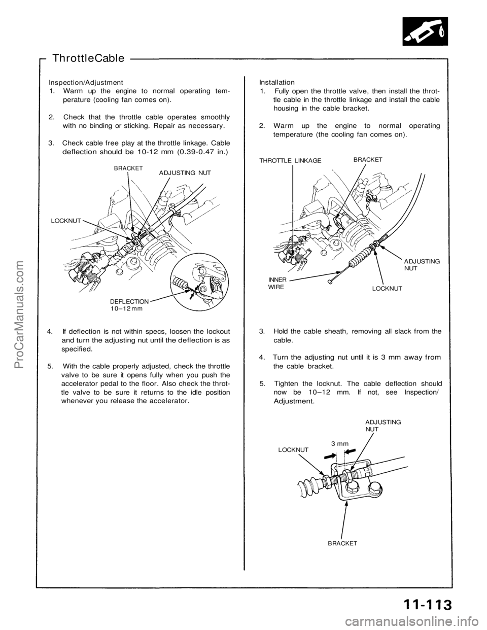
3. Check cable free play at the throttle linkage. Cable
deflection should be 10-12 mm (0.39-0.47 in.)
Installation
1. Fully open the throttle valve, then install the throt- tle cable in the throttle linkage and install the cablehousing in the cable bracket.
2. Warm up the engine to normal operating temperature (the cooling fan comes on).
THROTTLE LINKAGE
BRACKET
ADJUSTING
NUT
LOCKNUT
INNER
WIRE
ADJUSTING NUT
BRACKET
LOCKNUT
DEFLECTION
10–12
mm
4. If deflection is not within specs, loosen the lockout
and turn the adjusting nut until the deflection is as
specified.
5. With the cable properly adjusted, check the throttle valve to be sure it opens fully when you push the
accelerator pedal to the floor. Also check the throt-
tle valve to be sure it returns to the idle position whenever you release the accelerator. 3. Hold the cable sheath, removing all slack from the
cable.
4. Turn the adjusting nut until it is 3 mm away from
the cable bracket.
5. Tighten the locknut. The cable deflection should now be 10–12 mm. If not, see Inspection/
Adjustment.
ADJUSTING
NUT
LOCKNUT
3 mm
BRACKETProCarManuals.com
Page 1520 of 1640

Air Intake System
Throttle Body
Description
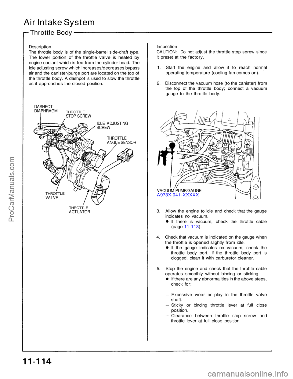
The throttle body is of the single-barrel side-draft type.
The lower portion of the throttle valve is heated by
engine coolant which is fed from the cylinder head. Theidle adjusting screw which increases/decreases bypass
air and the canister/purge port are located on the top of
the throttle body. A dashpot is used to slow the throttle as it approaches the closed position.
Inspection
CAUTION: Do not adjust the throttle stop screw since
it preset at the factory.
1. Start the engine and allow it to reach normal operating temperature (cooling fan comes on).
2. Disconnect the vacuum hose (to the canister) from the top of the throttle body; connect a vacuum
gauge to the throttle body.
DASHPOT
DIAPHRAGM
THROTTLE
STOP SCREW
IDLE ADJUSTING
SCREW
THROTTLE
ANGLE SENSOR
VACUUM PUMP/GAUGE
A973X-041 -XXXXX
THROTTLE
VALVE
THROTTLE
ACTUATOR
3. Allow the engine to idle and check that the gauge
indicates no vacuum. If there is vacuum, check the throttle cable
(page 11-113).
4. Check that vacuum is indicated on the gauge when
the throttle is opened slightly from idle.
If the gauge indicates no vacuum, check the
throttle body port. If the throttle body port is clogged, clean it with carburetor cleaner.
5. Stop the engine and check that the throttle cable operates smoothly without binding or sticking. If there are any abnormalities in the above steps,
check for:
Excessive wear or play in the throttle valve
shaft.
Sticky or binding throttle lever at full close
position.
Clearance between throttle stop screw and
throttle lever at full close position.ProCarManuals.com
Page 1524 of 1640
Chamber Volume Control System
Description
Satisfactory power performance is achieved by closing and opening the chamber volume control valves. High torque at
low RPM is achieved when the valves are closed, whereas high power at high RPM is achieved by when the valves are
opened.
CHAMBER VOLUME CONTROL SOLENOID
VALVE ON
ENGINE RPM IS ABOVE 4,800 rpm
OPEN
BLK/YEL
To No. 2 FUSE
CLOSE
CHECK
VALVE
VACUUM
TANK
RED/BLU
ECU
CHAMBER
VOLUME
CONTROL
DIAPHRAGM
CHAMBER
VOLUME
CONTROL
VALVE
(cont'd)ProCarManuals.com
Page 1528 of 1640
System Description
Tailpipe Emission
The emission control system includes a three-way catalytic converter, exhaust gas recirculation (EGR) system,
crankcase ventilation system and evaporative control
system.
The emission control system is designed to meet federal and
state emission standards.
Inspection
Do not smoke during this procedure. Keep
any open flame away from your work area.
1. Starting the engine and warm it up to normal operating temperature by driving the car on theroad.
2. Connect a tachometer.
3. Check idle speed and adjust the idle speed, if necessary (page 11-84).
4. Warm up and calibrate the CO meter according to the meter manufacturer's instructions.
5. Check idle CO with the headlights, heater blower, rear window defogger, cooling fan, and air conditioner off.
CO meter should indicate 0.1 % maximum.ProCarManuals.com
Page 1531 of 1640
Emission Control System
Positive Crankcase Ventilation System
Description The Positive Crankcase Ventilation (PCV) system is
designed to prevent blow-by gas from escaping to theatmosphere. The PCV valve contains a spring-loaded
plunger. When the engine starts, the plunger in the PCV
valve is lifted in proportion to intake manifold vacuum and
the blow-by gas is drawn directly into the intake manifold.
PCV HOSE
BLOW-BY VAPOR
FRESH AIR
PCV VALVE
Inspection
1 Check the crankcase ventilation hoses and connec- tions for leaks and clogging.
BREATHER
PIPE
2. At idle, make sure there is a clicking sound from the PCV valve when the hose between PCV valve and
intake manifold in lightly pinched with your fingers or
pliers.
If there is no clicking sound, check the PCV valve
grommet for cracks or damage. If the grommet is
OK, replace the PCV valve and recheck.
PCV VALVE
PCV HOSE
Gently pinch here
BREATHER HOSE
FRONT OF
VEHICLEProCarManuals.com