Page 1002 of 1640
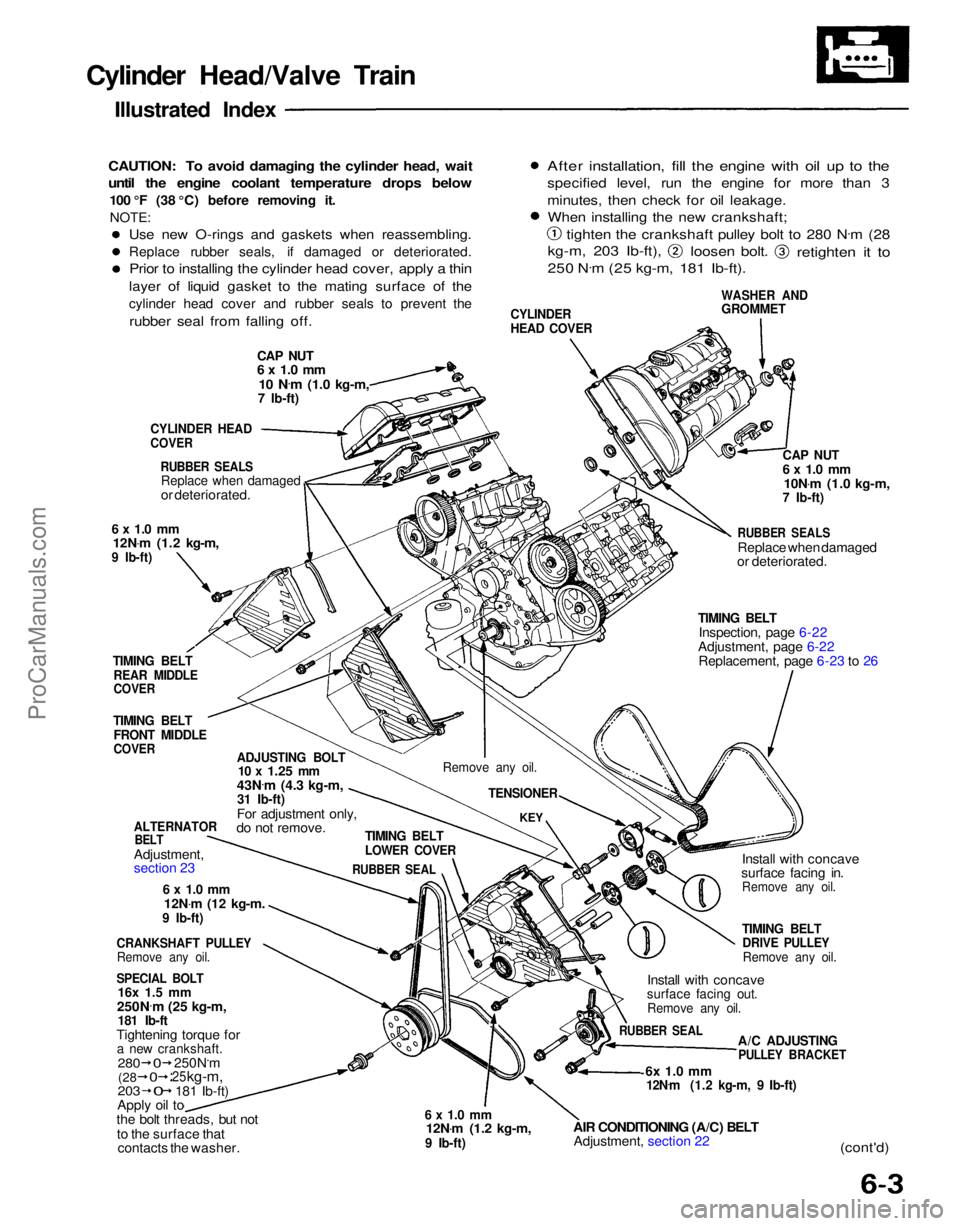
Cylinder Head/Valve Train
Illustrated Index
CAUTION: To avoid damaging the cylinder head, wait
until the engine coolant temperature drops below
100 °F (38 °C) before removing it.NOTE:
CAP NUT
6 x 1.0 mm
10 N .
m
(1.0 kg-m,
7 Ib-ft)
CYLINDER
HEAD COVER
WASHER AND
GROMMET
After installation, fill the engine with oil up to the
specified level, run the engine for more than 3
minutes, then check for oil leakage.
When installing the new crankshaft;
tighten the crankshaft pulley bolt to 280 N .
m (28
kg-m, 203 Ib-ft),
loosen bolt.
retighten it to
250 N .
m (25 kg-m, 181 Ib-ft).
CYLINDER HEAD
COVER
RUBBER SEALS
Replace when damaged
or deteriorated.
6 x 1.0 mm
12N .
m (1.2 kg-m,
9 Ib-ft)
TIMING BELT
REAR MIDDLE
COVER
TIMING BELT
FRONT MIDDLE
COVER
ADJUSTING BOLT
10 x
1.25
mm
43N .
m (4.3 kg-m,
31 Ib-ft)
For adjustment only,
do not remove.
ALTERNATOR
BELT
Adjustment,
section 23
6 x 1.0 mm
12N .
m
(12
kg-m.
9 Ib-ft)
CRANKSHAFT PULLEY
Remove any oil.
SPECIAL BOLT
16x 1.5 mm
250N .
m (25 kg-m,
181 Ib-ft
Tightening torque for
a new crankshaft.
203
Apply oil to
the bolt threads, but not
to the surface that contacts the washer.
6 x 1.0 mm
12N .
m (1.2 kg-m,
9 Ib-ft)
AIR CONDITIONING (A/C) BELT
Adjustment, section 22
6x 1.0 mm
12N .
m (1.2 kg-m, 9 Ib-ft)
(cont'd)
A/C ADJUSTING
PULLEY BRACKET
RUBBER SEAL
Install with concave
surface facing out.
Remove any oil.
TIMING BELT
DRIVE PULLEY
Remove any oil.
Install with concave
surface facing in.
Remove any oil.
TIMING BELT
Inspection, page 6-22
Adjustment, page 6-22 Replacement, page 6-23 to 26
RUBBER SEALS
Replace when damaged
or deteriorated.
CAP NUT
6 x 1.0 mm
10N .
m (1.0 kg-m,
7 Ib-ft)
TIMING BELT
LOWER COVER
RUBBER SEAL
KEY
Remove any oil.
TENSIONER
280
250N.m
25
kg-m,
181 Ib-ft)
(28
0
0
0
Use new O-rings and gaskets when reassembling.
Replace rubber seals, if damaged or deteriorated.
Prior to installing the cylinder head cover, apply a thin
layer of liquid gasket to the mating surface of the
cylinder head cover and rubber seals to prevent the
rubber seal from falling off.ProCarManuals.com
Page 1006 of 1640
1. Disconnect the 2P connector from the VTEC
solenoid valve.
2. Measure resistance between the YEL (front) or BLU/YEL (rear) terminal and body ground.
Resistance: approx 14—30 ohms 4. If filters are normal, push the VTEC solenoid valve
with your finger and check its movement.
FILTER
Replace.
YEL (front) or BLU/YEL (rear)
3. If the resistance is within specifications, remove the VTEC valve assembly from the cylinder head,and check the VTEC valve filter for clogging.
VTEC VALVE
ASSEMBLY
VTEC VALVE
FILTER
Replace.
6 x 1.0 mm
12 N ·
m (1,2 kg-m, 9 Ib-ft)
If there is clogging, replace the engine oil filter
and engine oil.
6x1.0
mm
12 N .
m (1.2 kg-m, 9 Ib-ft)
If VTEC solenoid valve is normal, check the
engine oil pressure.
VTEC Valve Inspection
VTEC
14
30ProCarManuals.com
Page 1007 of 1640
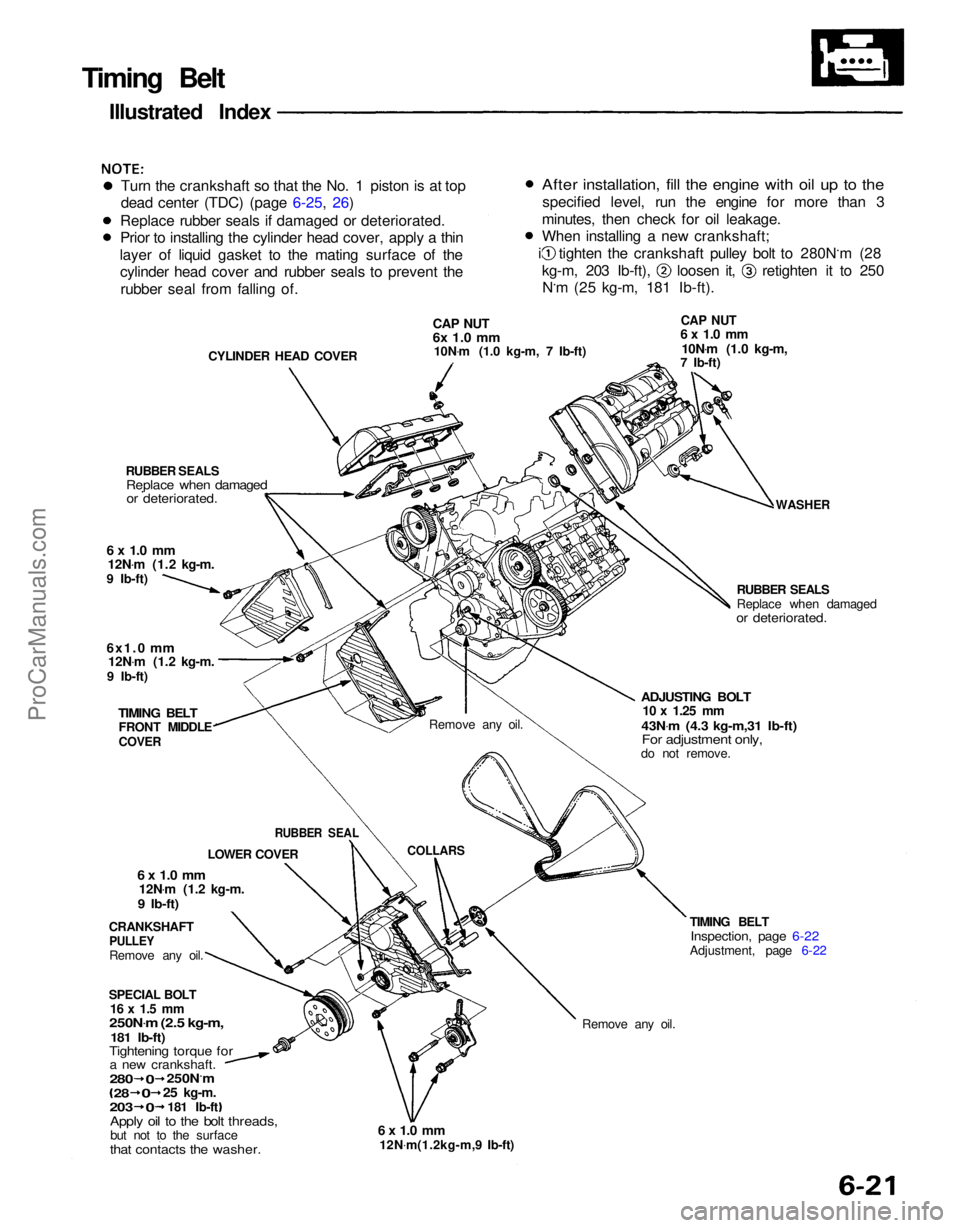
Remove any oil.
TIMING BELT
Inspection, page 6-22
Adjustment, page 6-22
6 x 1.0 mm
12N .
m(1.2kg-m,9 Ib-ft)
Timing Belt
Illustrated Index
Turn the crankshaft so that the No. 1 piston is at top
dead center (TDC) (page 6-25, 26)
Replace rubber seals if damaged or deteriorated.
Prior to installing the cylinder head cover, apply a thin
layer of liquid gasket to the mating surface of the cylinder head cover and rubber seals to prevent the
rubber seal from falling of.
CYLINDER HEAD COVER
CAP NUT
6x 1.0 mm
10N .
m (1.0 kg-m, 7 Ib-ft)
CAP NUT
6 x 1.0 mm
10N .
m (1.0 kg-m,
7 Ib-ft)
WASHER
RUBBER SEALS
Replace when damaged
or deteriorated.
ADJUSTING BOLT
10 x
1.25
mm
43N .
m (4.3 kg-m,31 Ib-ft)
For adjustment only,
do not remove.
Remove any oil.
COLLARS
RUBBER SEALS
Replace when damaged
or deteriorated.
6 x 1.0 mm
12N .
m (1.2 kg-m.
9 Ib-ft)
6x1.0
mm
12N .
m (1.2 kg-m.
9 Ib-ft)
TIMING BELT
FRONT MIDDLE
COVER
CRANKSHAFT
PULLEY
Remove any oil.
6 x 1.0 mm
12N .
m (1.2 kg-m.
9 Ib-ft)
SPECIAL BOLT
16 x 1.5 mm
250N .
m (2.5 kg-m,
181 Ib-ft)
Tightening torque for
a new crankshaft.
Apply oil to the bolt threads,
but not to the surface
that contacts the washer.
280
0
250N.m
28
0
25
kg-m.
203
0
181 Ib-ft LOWER COVER
RUBBER SEAL
After installation, fill the engine with oil up to the
specified level, run the engine for more than 3
minutes, then check for oil leakage.
When installing a new crankshaft; i tighten the crankshaft pulley bolt to 280N.m (28
kg-m, 203 Ib-ft), loosen it, retighten it to 250
N.m (25 kg-m, 181 Ib-ft).ProCarManuals.com
Page 1012 of 1640
Prior to installing the cylinder head cover, apply
a thin layer of liquid gasket to the mating surface
of the cylinder head cover and rubber seals to pre-
vent the rubber seal from falling off.
After
installation,
fill
the
engine
with
oil up to the
specified level, run the engine for more than 3 minutes, then check for oil leakage.
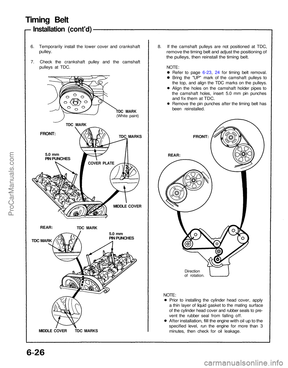
8. If the camshaft pulleys are not positioned at TDC,
remove the timing belt and adjust the positioning of
the pulleys, then reinstall the timing belt.
6. Temporarily install the lower cover and crankshaft
pulley.
7. Check the crankshaft pulley and the camshaft pulleys at TDC.
FRONT:
5.0 mm
PIN PUNCHES
MIDDLE COVER
REAR:
TDC MARK
5.0 mm
PIN PUNCHES
Direction
of rotation.
FRONT:
REAR:
TDC MARK
TDC MARK
(White paint)
TDC MARKS
COVER PLATE
TDC MARK
MIDDLE COVER TDC MARKS
Timing Belt
Installation (cont'd)
Refer to page 6-23, 24 for timing belt removal.
Bring the "UP" mark of the camshaft pulleys to
the top, and align the TDC marks on the pulleys.
Align the holes on the camshaft holder pipes to
the camshaft holes, insert 5.0 mm pin punches
and fix them at TDC.
Remove the pin punches after the timing belt has
been reinstalled.
NOTE:
NOTE:ProCarManuals.com
Page 1039 of 1640
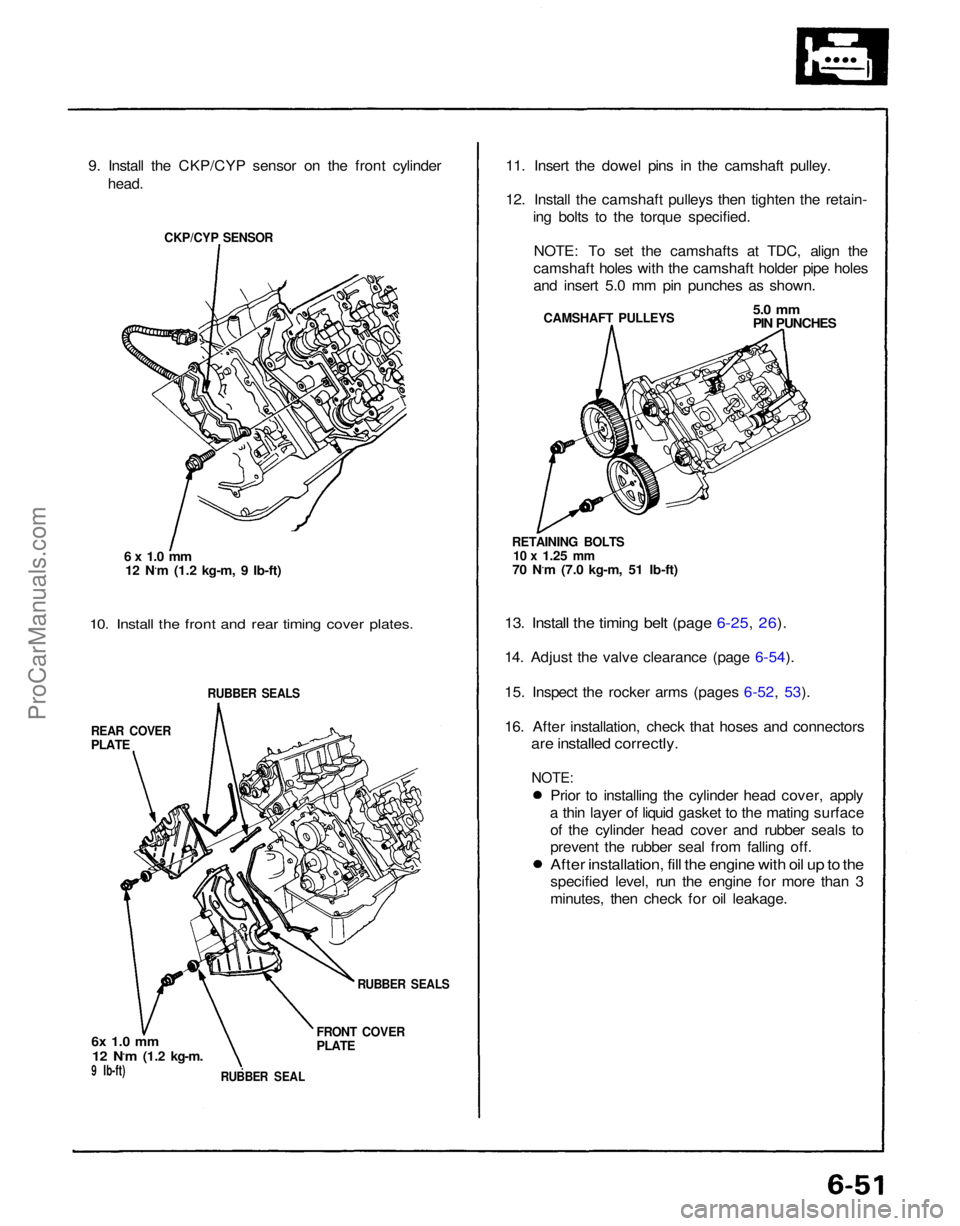
9. Install the CKP/CYP sensor on the front cylinder
head.
CKP/CYP SENSOR
6 x 1.0 mm
12 N.m (1.2 kg-m, 9 Ib-ft)
10. Install the front and rear timing cover plates.
RUBBER SEALS
REAR COVER
PLATE
6x 1.0 mm
12 N.m
(1.2 kg-m.
9 Ib-ft)
RUBBER SEAL
FRONT COVER
PLATE
RUBBER SEALS
11. Insert the dowel pins in the camshaft pulley.
12. Install the camshaft pulleys then tighten the retain-
ing bolts to the torque specified.
NOTE: To set the camshafts at TDC, align the
camshaft holes with the camshaft holder pipe holes
and insert 5.0 mm pin punches as shown.
CAMSHAFT PULLEYS
5.0 mm
PIN PUNCHES
RETAINING BOLTS
10 x
1.25
mm
70 N.m (7.0 kg-m, 51 Ib-ft)
13. Install the timing belt (page 6-25, 26).
14. Adjust the valve clearance (page 6-54).
15. Inspect the rocker arms (pages 6-52, 53).
16. After installation, check that hoses and connectors
are installed correctly.
Prior to installing the cylinder head cover, apply
a thin layer of liquid gasket to the mating surface of the cylinder head cover and rubber seals to
prevent the rubber seal from falling off.
After installation, fill the engine with oil up to the
specified level, run the engine for more than 3
minutes, then check for oil leakage.
NOTE:ProCarManuals.com
Page 1044 of 1640
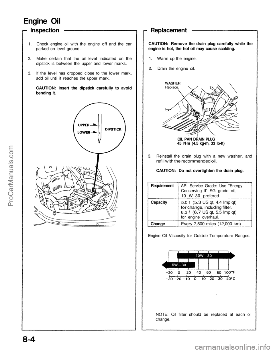
Engine Oil
Inspection
1. Check engine oil with the engine off and the car parked on level ground.
2. Make certain that the oil level indicated on the dipstick is between the upper and lower marks.
3. If the level has dropped close to the lower mark, add oil until it reaches the upper mark.
CAUTION: Insert the dipstick carefully to avoid
bending it. Replacement
CAUTION: Remove the drain plug carefully while the
engine is hot, the hot oil may cause scalding.
1. Warm up the engine.
2. Drain the engine oil.
WASHER
Replace.
OIL PAN DRAIN PLUG
45 N .
m (4.5 kg-m, 33 Ib-ft)
3. Reinstall the drain plug with a new washer, and
refill with the recommended oil.
CAUTION: Do not overtighten the drain plug.
Requirement
Capacity
Change API Service Grade: Use "Energy
Conserving II" SG grade oil,
10 W–30 prefered
5.0
Every 7,500 miles (12,000 km)
NOTE: Oil filter should be replaced at each oil
change.
Engine Oil Viscosity for Outside Temperature Ranges.
(5.3
US qt, 4.4 Imp qt)
for change, including filter.
6.3
(6.7
US qt, 5.5 Imp qt)
for engine overhaul.ProCarManuals.com
Page 1049 of 1640
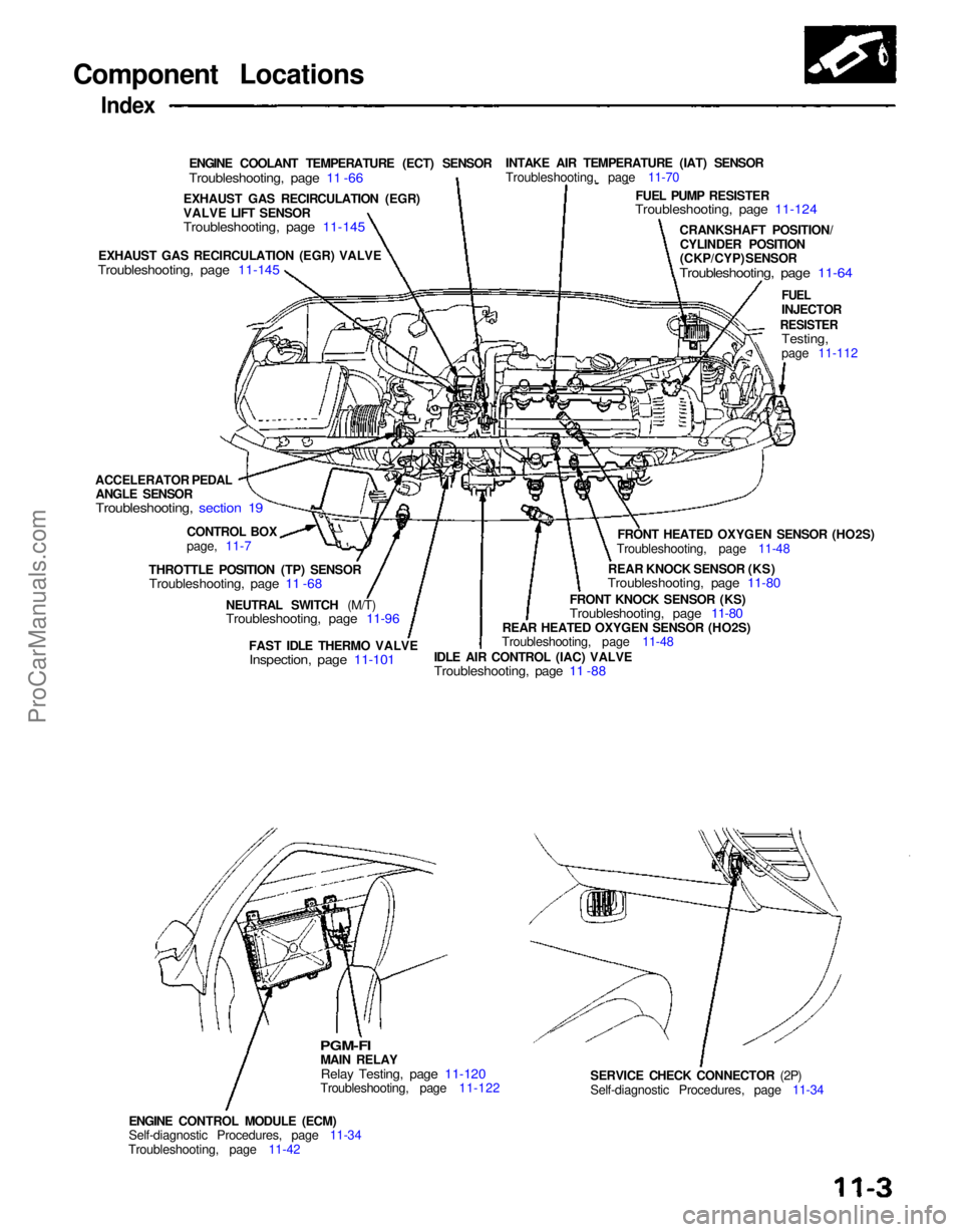
Component Locations
Index
ENGINE COOLANT TEMPERATURE (ECT) SENSOR
Troubleshooting, page 11 -66
INTAKE AIR TEMPERATURE (IAT) SENSOR
Troubleshooting, page 11-70
FUEL PUMP RESISTER
Troubleshooting, page 11-124
CRANKSHAFT POSITION/CYLINDER POSITION
(CKP/CYP) SENSOR
Troubleshooting, page 11-64
FUEL
INJECTOR
RESISTER
Testing,
page 11-112
FRONT HEATED OXYGEN SENSOR (HO2S)
Troubleshooting, page 11-48
REAR KNOCK SENSOR (KS)
Troubleshooting, page 11-80
FRONT KNOCK SENSOR (KS)
Troubleshooting, page 11-80
REAR HEATED OXYGEN SENSOR (HO2S)
Troubleshooting, page 11-48
IDLE AIR CONTROL (IAC) VALVE
Troubleshooting, page 11 -88
FAST IDLE THERMO VALVE
Inspection, page 11-101
NEUTRAL SWITCH (M/T)
Troubleshooting, page 11-96
SERVICE CHECK CONNECTOR (2P)
Self-diagnostic Procedures, page 11-34
ENGINE CONTROL MODULE (ECM)
Self-diagnostic Procedures, page 11-34
Troubleshooting, page 11-42
PGM-FI
MAIN RELAY
Relay Testing, page 11-120
Troubleshooting, page 11-122
THROTTLE POSITION (TP) SENSOR
Troubleshooting, page 11 -68
CONTROL BOX
page, 11-7
ACCELERATOR PEDAL
ANGLE SENSOR
Troubleshooting, section 19
EXHAUST GAS RECIRCULATION (EGR) VALVE
Troubleshooting, page 11-145
EXHAUST GAS RECIRCULATION (EGR)
VALVE LIFT SENSOR
Troubleshooting, page 11-145ProCarManuals.com
Page 1055 of 1640
System Description
Electrical Connections
FUSES
CLOCK (7.5 A)*
ACG
(120 A)**
ACG(S) (20 A)**
IG COIL (30 A)**
No. 2 (15 A)
No. 5 (10 A)
No.
4(15
A)
No. 7
(7.5
A)
In the under-hood
fuse/relay box In the engine
compartment
fuse/relay box
CKP/CYP
SENSOR
TO A/T
GEAR
POSITION
SWITCH
NEUTRAL
SWITCH
(M/T)
AUTO A/C
CONTROL
UNIT
CLUTCH
SWITCH
(M/T)
SERVICE
CHECK
CONNECTOR
A/C
PRESSURE
SWITCH A
A/C
PRESSURE
SWITCH B FUEL PUMP
RESISTORProCarManuals.com