1991 ACURA NSX check engine
[x] Cancel search: check enginePage 237 of 1640
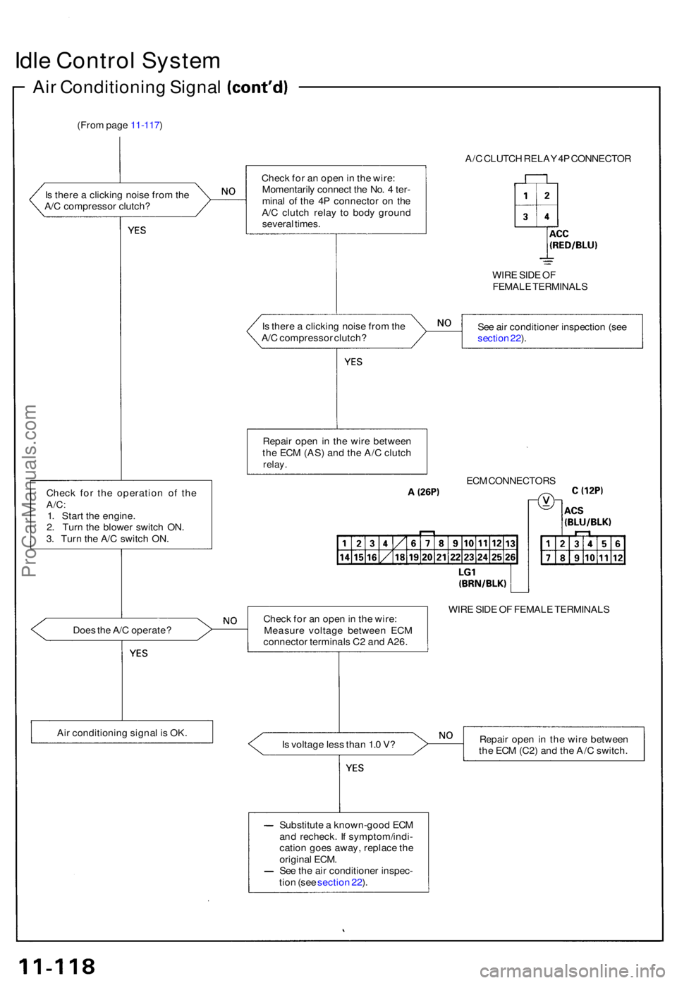
Idle Contro l Syste m
Air Conditionin g Signa l
(From pag e 11-117 )
I s ther e a clickin g nois e fro m th e
A/ C compresso r clutch ?
Chec k fo r th e operatio n o f th e
A/C :1. Star t th e engine .
2 . Tur n th e blowe r switc h ON .
3 . Tur n th e A/ C switc h ON .
Doe s th e A/ C operate ?
Ai r conditionin g signa l i s OK . A/
C CLUTC H RELA Y 4P CONNECTO R
Chec k fo r a n ope n in th e wire :
Momentaril y connec t th e No . 4 ter -
mina l o f th e 4 P connecto r o n th e
A/ C clutc h rela y t o bod y groun d
severa l times .
WIRE SID E O F
FEMAL E TERMINAL S
I s ther e a clickin g nois e fro m th e
A/ C compresso r clutch ? Se
e ai r conditione r inspectio n (se e
sectio n 22 ).
Repai r ope n in th e wir e betwee n
th e EC M (AS ) an d th e A/ C clutc h
relay.
ECM CONNECTOR S
Chec k fo r a n ope n in th e wire :
Measur e voltag e betwee n EC M
connecto r terminal s C 2 an d A26 . WIR
E SID E O F FEMAL E TERMINAL S
I s voltag e les s tha n 1. 0 V ? Repai
r ope n in th e wir e betwee n
th e EC M (C2 ) an d th e A/ C switch .
Substitut e a known-goo d EC M
an d recheck . I f symptom/indi -
catio n goe s away , replac e th e
origina l ECM .
Se e th e ai r conditione r inspec -
tio n (se e sectio n 22 ).
ProCarManuals.com
Page 238 of 1640
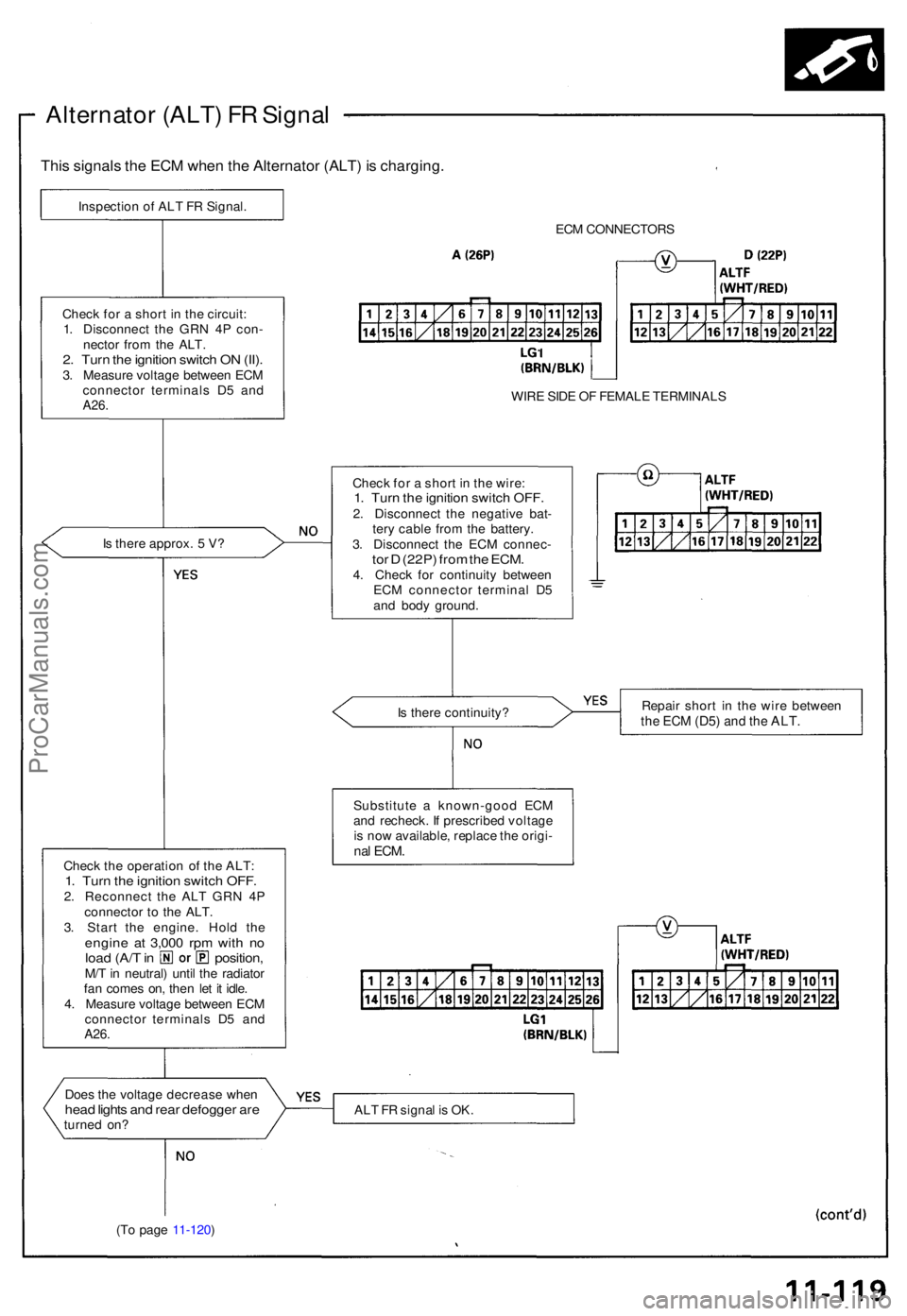
Alternator (ALT ) F R Signa l
This signal s th e EC M whe n th e Alternato r (ALT ) i s charging .
Inspection o f AL T F R Signal .
ECM CONNECTOR S
WIR E SID E O F FEMAL E TERMINAL S
Chec k fo r a shor t i n th e wire :
1. Tur n th e ignitio n switc h OFF .2. Disconnec t th e negativ e bat -
ter y cabl e fro m th e battery .
3 . Disconnec t th e EC M connec -
tor D (22P ) fro m th e ECM .4. Chec k fo r continuit y betwee n
EC M connecto r termina l D 5
an d bod y ground .
I
s ther e approx . 5 V ?
Chec
k fo r a shor t i n th e circuit :
1 . Disconnec t th e GR N 4 P con -
necto r fro m th e ALT .
2. Tur n th e ignitio n switc h O N (II) .3. Measur e voltag e betwee n EC M
connecto r terminal s D 5 an d
A26 .
Is ther e continuity ? Repai
r shor t i n th e wir e betwee nthe EC M (D5 ) and th e ALT .
Substitut e a known-goo d EC M
an d recheck . I f prescribe d voltag e
i s no w available , replac e th e origi -
nal ECM .Chec k th e operatio n o f th e ALT :1. Tur n th e ignitio n switc h OFF .2. Reconnec t th e AL T GR N 4 P
connecto r t o th e ALT .
3 . Star t th e engine . Hol d th e
engin e a t 3,00 0 rp m wit h n oloa d (A/ T in position ,M/T in neutral ) unti l th e radiato r
fa n come s on , the n le t i t idle .
4 . Measur e voltag e betwee n EC M
connecto r terminal s D 5 an d
A26.
Doe s th e voltag e decreas e whe nhead light s an d rea r defogge r ar eturne d on ? AL
T F R signa l i s OK .
(T o pag e 11-120 )
ProCarManuals.com
Page 242 of 1640
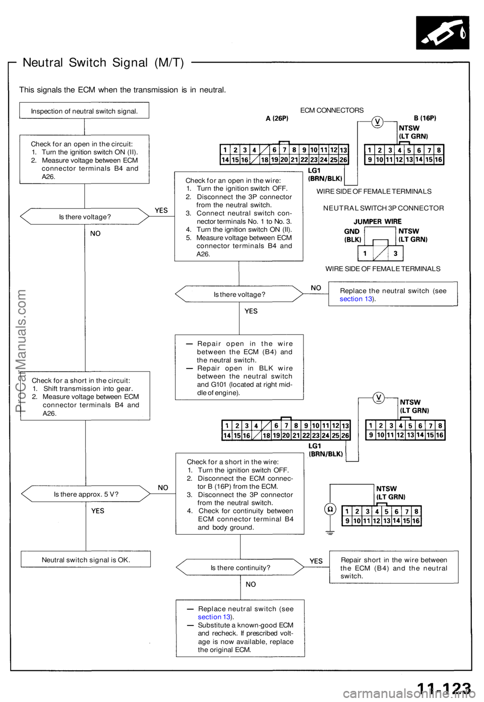
Neutral Switc h Signa l (M/T )
This signal s th e EC M whe n th e transmissio n i s i n neutral .
Inspectio n o f neutra l switc h signal .
Chec k fo r a n ope n in th e circuit :
1 . Tur n th e ignitio n switc h O N (II) .
2 . Measur e voltag e betwee n EC M
connecto r terminal s B 4 an d
A26 .
Is ther e voltage ?
Chec k fo r a shor t i n th e circuit :
1 . Shif t transmissio n int o gear .
2 . Measur e voltag e betwee n EC M
connecto r terminal s B 4 an d
A26 .
Is ther e approx . 5 V ?
Neutra l switc h signa l i s OK . EC
M CONNECTOR S
Chec k fo r a n ope n in th e wire :
1 . Tur n th e ignitio n switc h OFF .
2 . Disconnec t th e 3 P connecto r
fro m th e neutra l switch .
3 . Connec t neutra l switc h con -
necto r terminal s No . 1 to No . 3 .
4 . Tur n th e ignitio n switc h O N (II) .
5 . Measur e voltag e betwee n EC M
connecto r terminal s B 4 an d
A26 .
WIR E SID E O F FEMAL E TERMINAL S
WIR E SID E O F FEMAL E TERMINAL S
I s ther e voltage ? Replac
e th e neutra l switc h (se e
sectio n 13 ).
Repai r ope n i n th e wir e
betwee n th e EC M (B4 ) an d
th e neutra l switch .
Repai r ope n i n BL K wir e
betwee n th e neutra l switc h
an d G10 1 (locate d a t righ t mid -
dl e o f engine) .
Chec k fo r a shor t i n th e wire :
1 . Tur n th e ignitio n switc h OFF .
2 . Disconnec t th e EC M connec -
to r B (16P ) fro m th e ECM .
3 . Disconnec t th e 3 P connecto r
fro m th e neutra l switch .
4 . Chec k fo r continuit y betwee n
EC M connecto r termina l B 4
an d bod y ground .
I s ther e continuity ? Repai
r shor t i n th e wir e betwee n
th e EC M (B4 ) an d th e neutra l
switch .
Replac e neutra l switc h (se e
sectio n 13 ).
Substitut e a known-goo d EC M
an d recheck . I f prescribe d volt -
ag e i s no w available , replac e
th e origina l ECM . NEUTRA
L SWITC H 3 P CONNECTO R
ProCarManuals.com
Page 248 of 1640
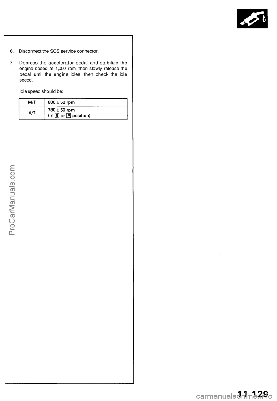
6. Disconnect the SCS service connector.
7. Depress the accelerator pedal and stabilize the
engine speed at 1,000 rpm, then slowly release the
pedal until the engine idles, then check the idle
speed.
Idle speed should be:ProCarManuals.com
Page 259 of 1640

Fuel Pum p Rela y
Troubleshootin g Flowchar t
Inspection o f fue l pum p relay .
Tur n th e ignitio n switc h t o STAR T
(III) position .
Does th e engin e start ?
Chec k fo r a n ope n in th e circuit :
1 . Sto p th e engine .
2. Tur n th e ignitio n switc h O N (II) .3. Measur e voltag e betwee n
EC M connecto r termina l F 4
an d bod y ground .
I s ther e batter y voltage ?
Proble m verification :
1 . Star t th e engine . Hol d th e
engin e a t 3,00 0 rp m wit h n o
loa d (A/ T in position ,M/T in neutral ) unti l th e radia -
to r fa n come s on , the n le t i t
idl e fo r a t leas t on e minute .
2. Tur n th e ignitio n switc h OFF .3. Disconnec t # 4 hos e fro m th e
instal l pipe , connec t vacuu m
pum p t o th e hose .
4 . Appl y vacuu m 2 7 t o 4 0 kp a
(200 t o 300 mmHg , 8 to 1 2in.Hg) .
5 . Star t th e engine .
6 . Hol d engin e spee d a t 6,50 0
rpm (A/ T in position ,M/T in neutral) .
7 . Measur e voltag e betwee n
EC M connecto r termina l F 4
an d bod y ground .
I s ther e les s tha n 1. 0 V ? Inspec
t th e fue l pum p resisto r
(se e pag e 11-141 ).
ECM CONNECTO R F (26P )
WIR E SID E O F FEMAL E TERMINAL S
(T o pag e 11-140 )
4 HOS E
CONTRO LBOX
VACUU M PUMP /GAUGEA973X-04 1-XXXX X
Substitut e a known-goo d EC M
an d recheck . I f prescribe d volt -
ag e i s no w available , replac e th e
origina l ECM .
Fue l pum p rela y circui t i s OK .
ProCarManuals.com
Page 296 of 1640
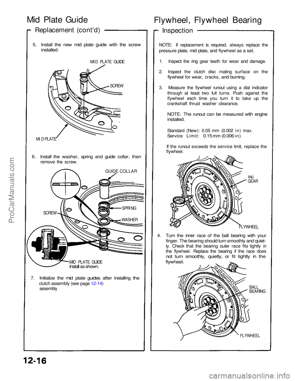
Mid Plate Guide
Replacement (cont'd)
5. Install the new mid plate guide with the screw
installed.
MII D PLATE GUIDE
SCREW
MI D PLATE
6. Install the washer, spring and guide collar, then
remove the screw.
GUIDE COLLAR
SCREW SPRI
NG
WASHER
MID PLATE GUIDE
Install as shown.
7. Initialize the mid plate guides after installing the
clutch assembly (see page 12-14)
assembly Flywheel, Flywheel Bearing
Inspection
NOTE: If replacement is required, always replace the
pressure plate, mid plate, and flywheel as a set.
1. Inspect the ring gear teeth for wear and damage.
2. Inspect the clutch disc mating surface on the
flywheel for wear, cracks, and burning.
3. Measure the flywheel runout using a dial indicator through at least two full turns. Push against the
flywheel esch time you turn it to take up the
crankshaft thrust washer clearance.
NOTE: The runout can be measured with engine
installed.
Standard (New): 0.05 mm (0.002 in) max.
Service Limit: 0.15 mm (0.006 in)
If the runout exceeds the service limit, replace the
flywheel.
RING
GEAR
FLYWHEEL
4. Turn the inner race of the ball bearing with your
finger. The bearing should turn smoothly and quiet-
ly. Check that the bearing outer race fits tightly in
the flywheel. Replace the bearing if the race does
not turn smoothly, quietly, or fit tightly in the
flywheel.
BALL
BEARING
FLYWHEELProCarManuals.com
Page 420 of 1640
Troubleshooting Precautions
EPS Indicator Light
Under normal conditions, the EPS indicator light in the gauge assembly comes on when the ignition switch is turned to
the ON (II) position, then goes off after the engine is started. This indicates that the bulb and its circuits are operating cor-
rectly. If there is any trouble in the system, the EPS indicator light turns on during driving, and the power steering assist is
turned off. When the EPS indicator light comes on, the control unit memorizes the DTC. In this case, the control unit does
not activate the EPS system after the engine starts again but it keeps the EPS indicator light on.
Diagnostic Trouble Code (DTC)
• The lowest DTC is indicated first.
• The DTCs continue blinking until the ignition switch is turned off.
• The DTCs are erased from the control unit when the EPS control unit VBU power supply or connector is disconnected.
• The EPS system can be reset and the control unit's memory can be erased by disconnecting the CLOCK (7.5 A) fuse for
more than ten seconds.
Self-diagnosis:
The CPU (central processing unit) controls the following when it detects a problem during self-diagnosis:
1. Turns the EPS indicator light ON to alert the driver.
2. Power assist stops, and normal manual steering operation resumes (except DTC 21 and DTC 33).
3. The EPS control unit memorizes the diagnostic trouble code (DTC).
4. After the DTC is stored in the control unit, the CPU stops self-diagnosis.
Troubleshooting:
• Before starting the troubleshooting, clear the DTC by disconnecting the CLOCK (7.5 A) fuse for ten seconds or more,
and test-drive the car. Check that the symptom of the trouble appears again, and then troubleshoot. If the problem is an
intermittent problem, the system does not become active after the engine starts even though the problem is solved.
• When both EPS indicator light and A/T "D" indicator light come on, perform the A/T troubleshooting first.
• When the customer's reported problem cannot be verified in the car, ask the customer about the conditions when the
EPS indicator light came ON, then test-drive the car under those conditions, if possible. If the EPS indicator light does
not come ON during the test, check for loose connections or poor contacts at the connectors by wiggling the harness,
etc.
• The connector terminal numbers are viewed from the wire side for the female terminals and from the terminal side for
the male terminals.
• After the repair, test-drive the car and check that the EPS indicator light does not come ON again during the test. (Refer
to the Symptom-to-System Chart for diagnostic period.)ProCarManuals.com
Page 521 of 1640
Anti-lock Brake System (ABS) Description
Features/Construction/Operation (cont'd)
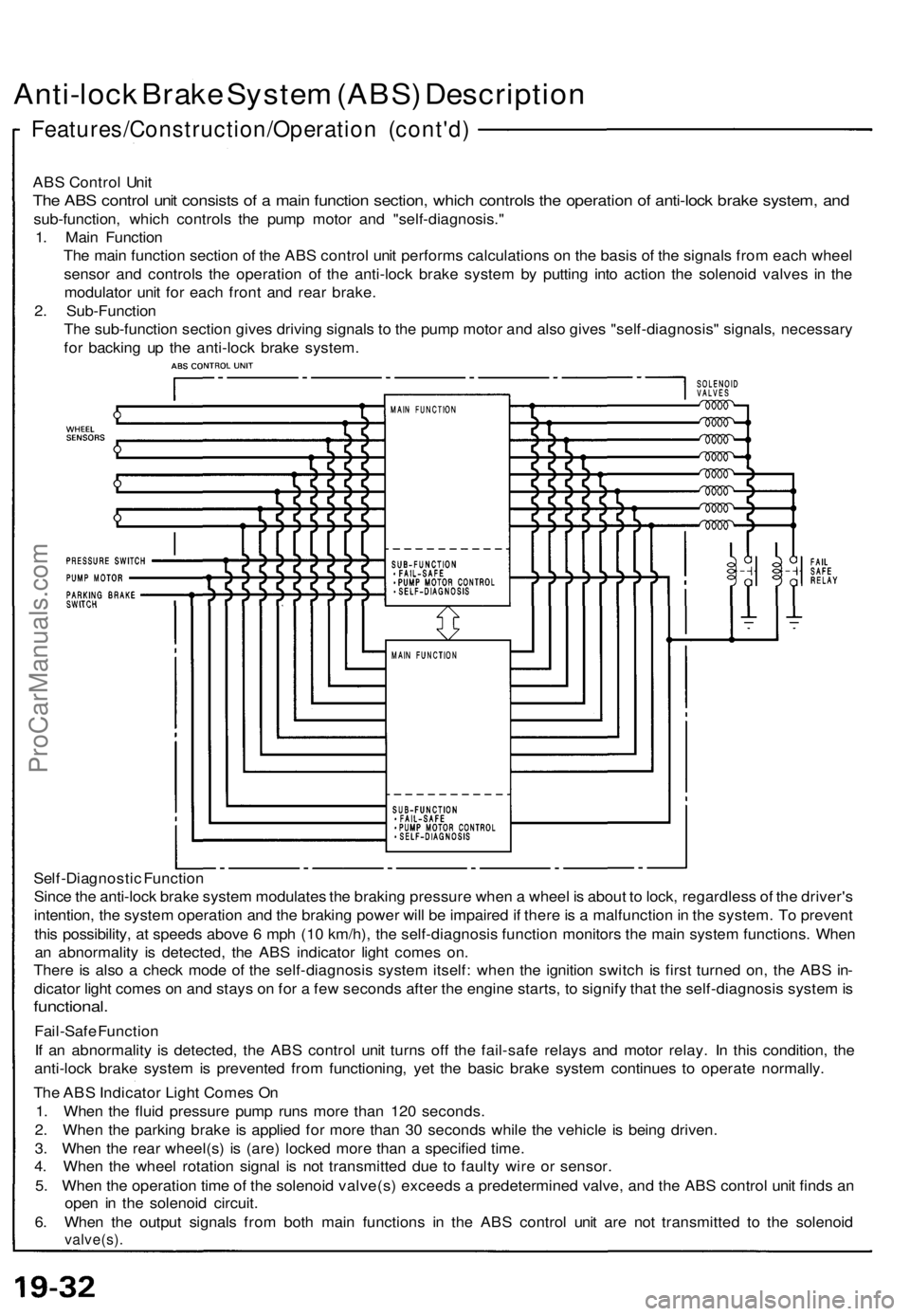
ABS Control Unit
The ABS control unit consists of a main function section, which controls the operation of anti-lock brake system, and
sub-function, which controls the pump motor and "self-diagnosis."
1. Main Function
The main function section of the ABS control unit performs calculations on the basis of the signals from each wheel
sensor and controls the operation of the anti-lock brake system by putting into action the solenoid valves in the
modulator unit for each front and rear brake.
2. Sub-Function
The sub-function section gives driving signals to the pump motor and also gives "self-diagnosis" signals, necessary
for backing up the anti-lock brake system.
Self-Diagnostic Function
Since the anti-lock brake system modulates the braking pressure when a wheel is about to lock, regardless of the driver's
intention, the system operation and the braking power will be impaired if there is a malfunction in the system. To prevent
this possibility, at speeds above 6 mph (10 km/h), the self-diagnosis function monitors the main system functions. When
an abnormality is detected, the ABS indicator light comes on.
There is also a check mode of the self-diagnosis system itself: when the ignition switch is first turned on, the ABS in-
dicator light comes on and stays on for a few seconds after the engine starts, to signify that the self-diagnosis system is
functional.
Fail-Safe Function
If an abnormality is detected, the ABS control unit turns off the fail-safe relays and motor relay. In this condition, the
anti-lock brake system is prevented from functioning, yet the basic brake system continues to operate normally.
The ABS Indicator Light Comes On
1. When the fluid pressure pump runs more than 120 seconds.
2. When the parking brake is applied for more than 30 seconds while the vehicle is being driven.
3. When the rear wheel(s) is (are) locked more than a specified time.
4. When the wheel rotation signal is not transmitted due to faulty wire or sensor.
5. When the operation time of the solenoid valve(s) exceeds a predetermined valve, and the ABS control unit finds an
open in the solenoid circuit.
6. When the output signals from both main functions in the ABS control unit are not transmitted to the solenoid
valve(s).ProCarManuals.com