Page 784 of 1640
Fan Relay Tests
Check continuity at the relay terminals.
• There should be continuity between the C and D ter-
minals.
• There should be continuity between the A and B ter-
minals when power and ground are connected to the
C and D terminals.
• There should be no continuity between the A and B
terminals when power is disconnected.
• Radiator fan low relay
• Radiator fan high relay
• Condenser fan relay
Engine compartment fan relay (A/T)ProCarManuals.com
Page 860 of 1640

(G551) '95-'96 Models.
(G401,G402,G551) '93-94 Models or
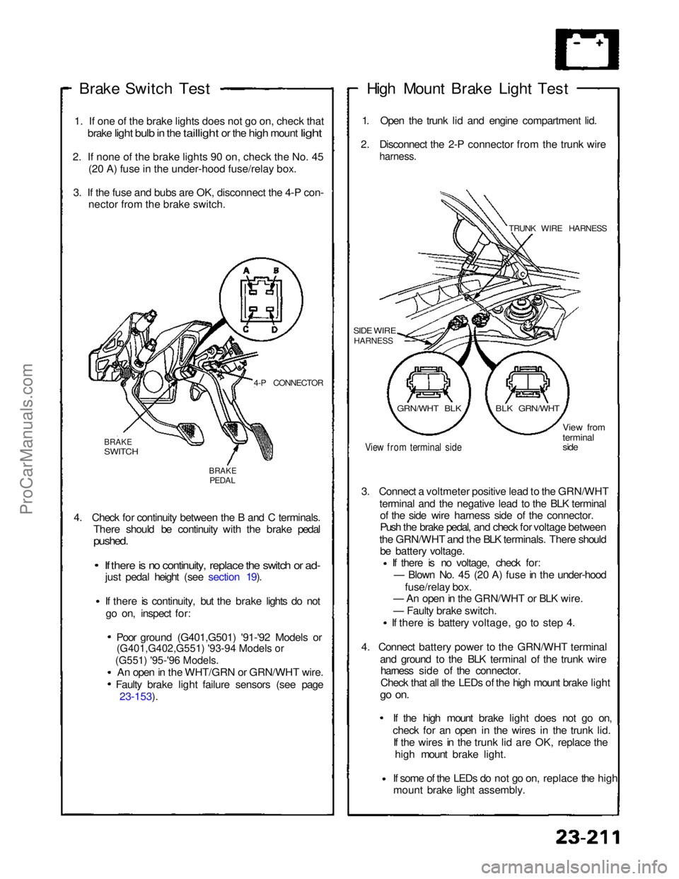
Brake Switch
Test
1
.
If one of the brake lights does not go on, check that
brake
light bulb in the taillight or the high mount light
2
.
If none of the brake lights 90 on, check the No. 45 (2
0
A) fuse in the under-hood fuse/relay box.
3
.
If the fuse and bubs are OK, disconnect the 4-P con- necto
r
from the brake switch.
4-P CONNECTOR
BRAKE
SWITCH
BRAKE
PEDAL
4. Check for continuity between the B and C terminals. There should be continuity with the brake pedal
pushed.
If there is no continuity, replace the switch or ad-
just pedal height (see section 19).
If there is continuity, but the brake lights do not
go on, inspect for:
Poor ground (G401,G501) '91-'92 Models or
An open in the WHT/GRN or GRN/WHT wire. Faulty brake light failure sensors (see page 23-153). High Mount Brake Light Test
1. Open the trunk lid and engine compartment lid.
2. Disconnect the 2-P connector from the trunk wire
harness.
TRUNK WIRE HARNESS
SIDE WIRE
HARNESS
View from terminal side
View from
terminal
side
3. Connect a voltmeter positive lead to the GRN/WHT terminal and the negative lead to the BLK terminalof the side wire harness side of the connector.
Push the brake pedal, and check for voltage between
the GRN/WHT and the BLK terminals. There should be battery voltage. If there is no voltage, check for:
— Blown No. 45 (20 A) fuse in the under-hood
fuse/relay box.
— An open in the GRN/WHT or BLK wire.
— Faulty brake switch.
If there is battery voltage, go to step 4.
4. Connect battery power to the GRN/WHT terminal and ground to the BLK terminal of the trunk wireharness side of the connector.
Check that all the LEDs of the high mount brake light
go on.
If the high mount brake light does not go on,check for an open in the wires
in the trunk lid.
If the wires in the trunk lid are OK, replace the
high mount brake light.
If some of the LEDs do not go on,
replace the high
mount brake light assembly.
GRN/WHT BLK
BLK GRN/WHTProCarManuals.com
Page 956 of 1640
Engine Compartment Lid Switch
Test
1. Open the engine compartment lid.
2. Disconnect the 2-P connector from the engine
compartment lid switch.
3. Check continuity at the switch connector terminals.
• There should be continuity between the terminals
with the lever released (lid open).
• There should be no continuity with the lever
pushed down (lid closed).
LEVER
View from
terminal side
2-P CONNECTOR
Hood Switch Test
1. Open the hood.
2. Disconnect the 2-P connector from the hood
switch.
3. Check continuity at switch connector terminals.
• There should be continuity between the terminals
with the lever released (hood open).
• There should be no continuity with the lever
pushed down (hood closed).
LEVER
2-P CONNECTOR
View from
terminal sideProCarManuals.com
Page 966 of 1640

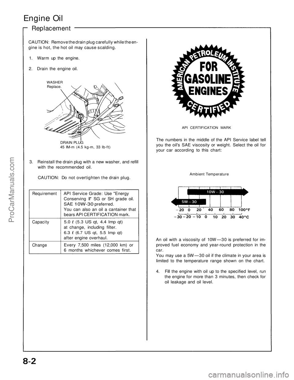
Engine Oil
Replacement
CAUTION: Remove the drain plug carefully while the en-
gine is hot, the hot oil may cause scalding.
1. Warm up the engine.
2. Drain the engine oil.
WASHER
Replace.
DRAIN PLUG
45 IM-m (4.5 kg-m, 33 Ib-ft)
3. Reinstall the drain plug with a new washer, and refill
with the recommended oil.
CAUTION: Do not overtighten the drain plug.
Requirement
API Service Grade: Use "Energy
Conserving II" SG or SH grade oil.
SAE
10W-30
preferred.
You can also an oil a cantainer that
bears API CERTIFICATION mark.
Capacity
5.0
(5.3
US qt, 4.4 Imp qt)
at change, including filter.
6.3
(6.7
US qt, 5.5 Imp qt)
after engine overhaul.
Change
Every 7,500 miles (12,000 km) or
6 months whichever comes first.
API CERTIFICATION MARK
The numbers in the middle of the API Service label tell
you the oil's SAE viscosity or weight. Select the oil for
your car according to this chart:
Ambient Temperature
An oil with a viscosity of 10W —30 is preferred for im-
proved fuel economy and year-round protection in the
car.
You may use a 5W —30 oil if the climate in your area is
limited to the temperature range shown on the chart.
4. Fill the engine with oil up to the specified level, run
the engine for more than 3 minutes, then check for
oil leakage and oil level.ProCarManuals.com
Page 995 of 1640
Engine Removal/Installation
(cont'd)
49. Remove the two bolts from the side engine mount near the alternator. Pivot the mounting bracket into
the housing of the body.
50. Remove the transmission mounting bolt.
51. Remove the twelve subframe-to-body mounting
bolts.
52. Raise the car a few inches.
53. Check that all wires and hoses are disconnected
from the engine assembly.
54. Raise the car completely off the engine/suspension assembly. Roll the assembly from under the car.
TRUCK GUIDE HOLE
(BODY)
TAPERED PUNCH
GUIDE HOLE
(SIDE BEAM)
NOTE: When installing, align the bolt holes of the
beam brackets and body with a tapered punch.ProCarManuals.com
Page 996 of 1640
55. Attach a chain hoist to the engine. Remove the
front and rear mounting bolts, then separate the
engine from the suspension and the beam
assembly.
CAUTION: Do not hit the engine oil cooler on the
rear right beam bracket.
FRONT ENGINE
MOUNT
REAR ENGINE
MOUNT
56. Install the engine in the reverse order of removal:
NOTE:
Combine the front beam and the rear beam rod
assembly, then torque the four mounting bolts.
Check that the set ring on the end of each
driveshaft clicks into place.
CAUTION: Use new set rings.
(cont'd)
Align the bolt holes of the beam brackets and
body with a tapered punch (page 5-28).
Temporarily torque the two front beam nuts and
front engine mounting bolt when installing the
A/C compressor.ProCarManuals.com
Page 997 of 1640
55. Attach a chain hoist to the engine. Remove the
front and rear mounting bolts, then separate the
engine from the suspension and the beam
assembly.
CAUTION: Do not hit the engine oil cooler on the
rear right beam bracket.
FRONT ENGINE
MOUNT
REAR ENGINE
MOUNT
56. Install the engine in the reverse order of removal:
NOTE:
Combine the front beam and the rear beam rod
assembly, then torque the four mounting bolts.
Check that the set ring on the end of each
driveshaft clicks into place.
CAUTION: Use new set rings.
(cont'd)
Align the bolt holes of the beam brackets and
body with a tapered punch (page 5-28).
Temporarily torque the two front beam nuts and
front engine mounting bolt when installing the
A/C compressor.ProCarManuals.com
Page 998 of 1640

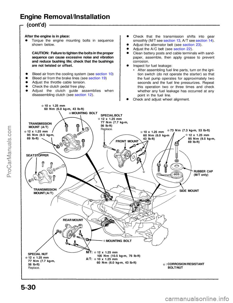
Engine Removal/Installation
(cont'd)
Torque the engine mounting bolts in sequenceshown below.
CAUTION: Failure to tighten the bolts in the proper
sequence can cause excessive noise and vibration
and reduce bushing life; check that the bushings
are not twisted or offset.
Bleed air from the cooling system (see section 10)
Bleed air from the brake lines (see section 19)
Adjust the throttle cable tension.
Check the clutch pedal free play.
Adjust the clutch guide assemblies when
disassembling clutch (see section 12). Check that the transmission shifts into gear
smoothly (M/T see section 13, A/T see section 14).
Adjust the alternator belt (see section 23).
Adjust the A/C belt (see section 22).
Clean battery posts and cable terminals with sand-
paper, assemble, then apply grease to prevent
corrosion.
Inspect for fuel leakage:
• After assembling fuel line parts, turn on the igni- tion switch (do not operate the starter) so that
the fuel pump operates for approximately two seconds and the fuel line pressurizes. Repeat
this operation two or three times and check whether any fuel leakage has occurred at any
point in the fuel line.
Check and adjust wheel alignment.
10 x
1.25
mm
60 N .
m (6.0 kg-m, 43 Ib-ft)
MOUNTING BOLT SPECIAL BOLT
12 x
1.25
mm
77 N .
m
(7.7 kg-m,
56 Ib-ft)
Replace.
10 x
1.25
mm
60 N .
m
(6.0 kg-m
43 Ib-ft) 73 N.m (7.3 kg-m, 53 Ib-ft)
12 x
1.25
mm
95 N .
m
(9.5 kg-m,
69 Ib-ft)
RUBBER CAP
(M/T only)
SIDE MOUNT
: CORROSION RESISTANT
BOLT/NUT
12 x
1.25
mm
105 N .
m (10.5 kg-m, 76 Ib-ft)
10 x
1.25
mm
60 N .
m (6.0 kg-m, 43 Ib-ft) MOUNTING BOLT FRONT MOUNT
TRANSMISSION
MOUNT (A/T)
12 x
1.25
mm
95 N .
m
(9.5 kg-m,
69 Ib-ft)
SEAT STOPPER
TRANSMISSION
MOUNT (A/T)
REAR MOUNT
SPECIAL NUT
12 x
1.25
mm
77 N .
m
(7.7 kg-m,
56 Ib-ft)
Replace.
M/T:
A/T:
After the engine is in place:ProCarManuals.com