1991 ACURA NSX check engine
[x] Cancel search: check enginePage 531 of 1640
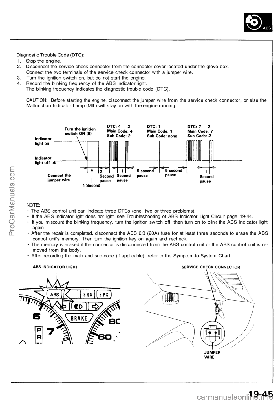
Diagnostic Trouble Code (DTC):
1. Stop the engine.
2. Disconnect the service check connector from the connector cover located under the glove box.
Connect the two terminals of the service check connector with a jumper wire.
3. Turn the ignition switch on, but do not start the engine.
4. Record the blinking frequency of the ABS indicator light.
The blinking frequency indicates the diagnostic trouble code (DTC).
CAUTION: Before starting the engine, disconnect the jumper wire from the service check connector, or else the
Malfunction Indicator Lamp (MIL) will stay on with the engine running.
NOTE:
• The ABS control unit can indicate three DTCs (one, two or three problems).
• If the ABS indicator light does not light, see Troubleshooting of ABS Indicator Light Circuit page 19-44.
• If you miscount the blinking frequency, turn the ignition switch off, then turn on to blink the ABS indicator light
again.
• After the repair is completed, disconnect the ABS 2,3 (20A) fuse for at least three seconds to erase the ABS
control unit's memory. Then turn the ignition key on again and recheck.
• The memory is erased if the connector is disconnected from the ABS control unit or the ABS control unit is re-
moved from the body.
• After recording the main and sub-code (if applicable), refer to the Symptom-to-System Chart.ProCarManuals.com
Page 558 of 1640
Steering angle sensor system check
1. Start the engine,
2. Push the TCS switch three times within three seconds.
NOTE: Always maintain the same number of rota-
tions.
3. Turn the steering wheel slowly from left to right more than 1.5 turns.
NOTE:
Start checking after the steering wheel moves at
least 1.5 turns from right to left.
Turn the steering wheel slowly, no faster than
one turn in four seconds.
4. Push the TCS switch twice within three seconds. NOTE: Always maintain the same number of rota-
tions.
5. Return the steering wheel to the left side slowly, and check the number of times the TCS indicator light
flashes after the wheel has moved approximately
one turn.
NOTE:
Start the check from the beginning when the steer-ing wheel moves at least one turn from left to
right, Turn the steering wheel slowly, no faster than one
turn in four seconds.
Standard number of times the TCS indicator light
flashes:
Manual Transmission: 5 times
Automatic Transmission: 2 times
6. If there is an abnormality, check the troubleshooting flowchart (see page 19-98('91-'93)('94-'96)
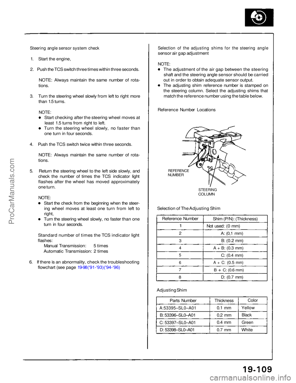
Selection of the adjusting shims for the steering angle
sensor air gap adjustment
NOTE:
The adjustment of the air gap between the steeringshaft and the steering angle sensor should be carried
out in order to obtain adequate sensor output.
The adjusting shim reference number is stamped on
the steering column. Select the adjusting shims that match the reference number using the table below.
Reference Number Locations
REFERENCE
NUMBER
STEERING
COLUMN
Selection of The Adjusting Shim
Adjusting Shim Parts Number
A:53395–SL0–A01
B: 53396–SL0–A01
C: 53397–SL0–A01
D: 53398–SL0–A01
Thickness
0.1 mm
0.2 mm
0.4 mm
0.7 mm
Color
Yellow
Black
Green
White
Reference Number
1
2
3
4
5
6
7
8
Shim (P/N): (Thickness)
Not used: (0 mm)
A:
(0,1
mm)
B:
(0.2
mm)
A + B:
(0.3
mm)
C:
(0.4
mm)
A + C:
(0.5
mm)
B + C:
(0.6
mm)
D:
(0.7
mm)ProCarManuals.com
Page 686 of 1640
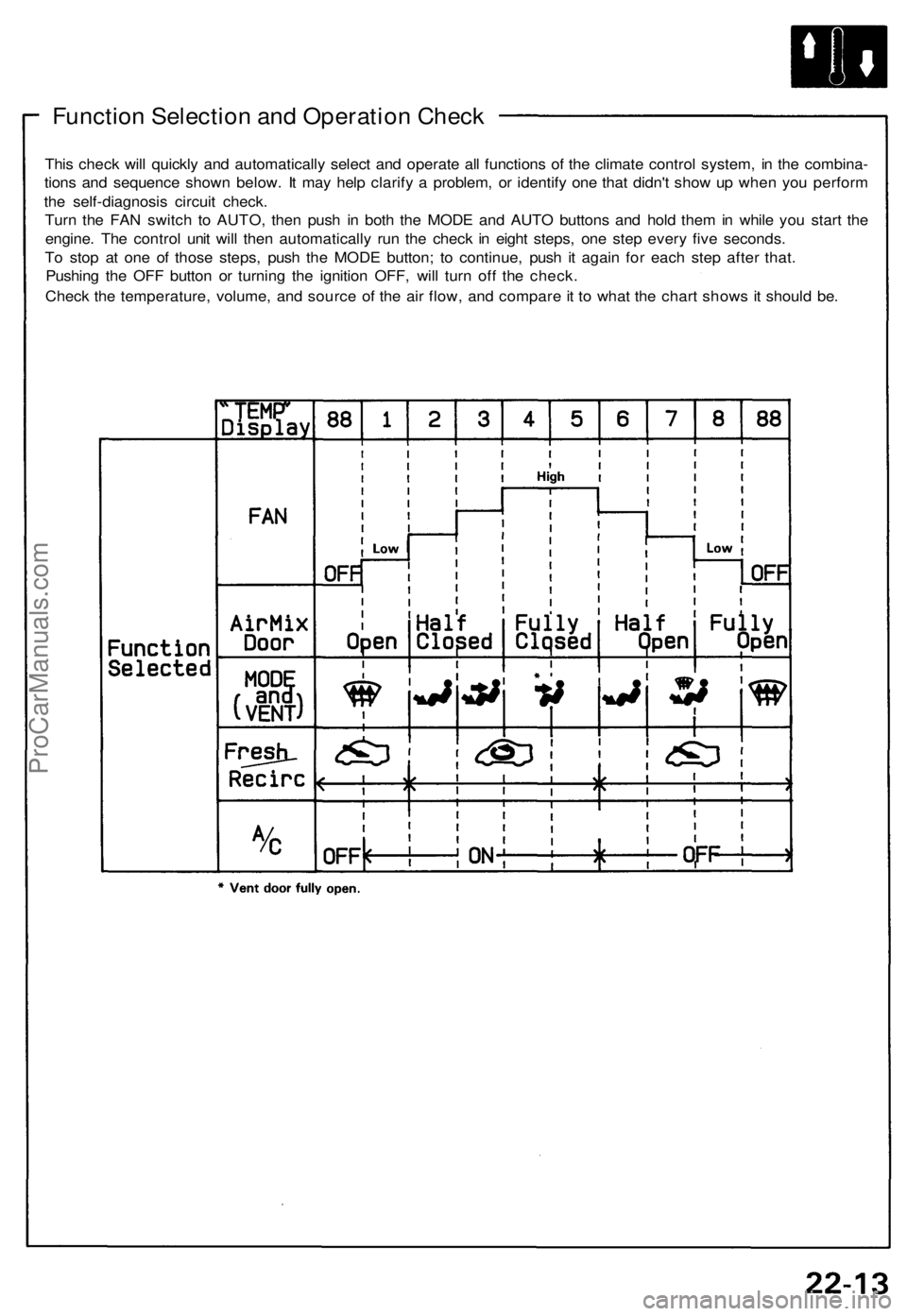
Function Selection and Operation Check
This check will quickly and automatically select and operate all functions of the climate control system, in the combina-
tions and sequence shown below. It may help clarify a problem, or identify one that didn't show up when you perform
the self-diagnosis circuit check.
Turn the FAN switch to AUTO, then push in both the MODE and AUTO buttons and hold them in while you start the
engine. The control unit will then automatically run the check in eight steps, one step every five seconds.
To stop at one of those steps, push the MODE button; to continue, push it again for each step after that.
Pushing the OFF button or turning the ignition OFF, will turn off the check.
Check the temperature, volume, and source of the air flow, and compare it to what the chart shows it should be.ProCarManuals.com
Page 687 of 1640
Troubleshooting
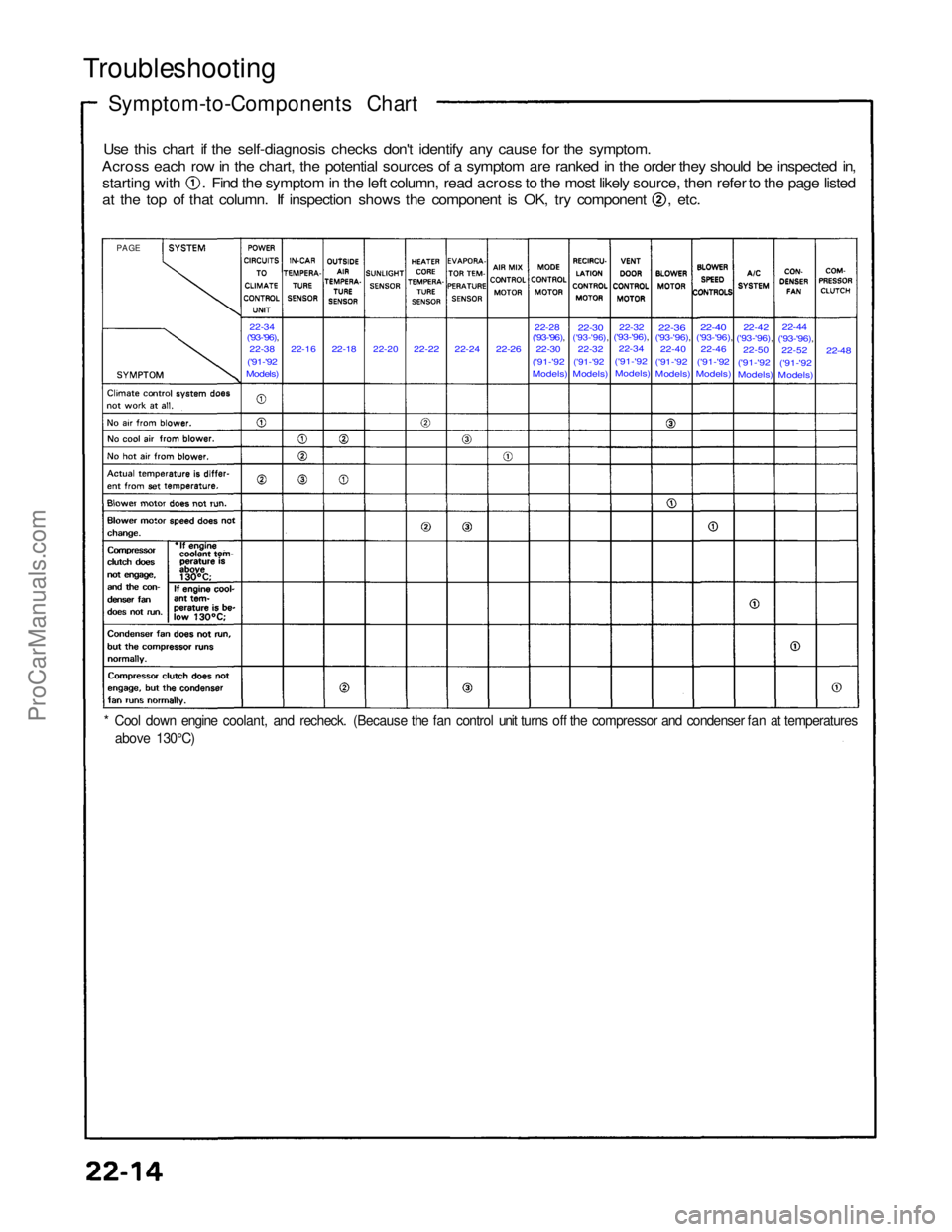
Symptom-to-Components Chart
Use this chart if the self-diagnosis checks don't identify any cause for the symptom.
Across each row in the chart, the potential sources of a symptom are ranked in the order they should be inspected in, starting with . Find the symptom in the left column, read across to the most likely source, then refer to the page listed
at the top of that column. If inspection shows the component is OK, try component , etc.
22-34
('93-'96),
22-38
('91-'92
Models)
22-16
22-18
22-20
22-22
22-24
22-26
22-30
('93-'96),22-28
('91-'92
Models)
22-30
('93-'96),
22-32
('91-'92
Models)
22-32
('93-'96),
22-34
('91-'92 Models)
22-36
('93-'96),
22-40
('91-'92 Models)
22-40
('93-'96),
22-46
('91-'92
Models)
22-42
('93-'96),
22-50
('91-'92 Models)
22-44
('93-'96),
22-52
('91-'92
Models)
22-48
PAGE
* Cool down engine coolant, and recheck. (Because the fan control unit turns off the compressor and condenser fan at temperatures above 130°C)ProCarManuals.com
Page 729 of 1640
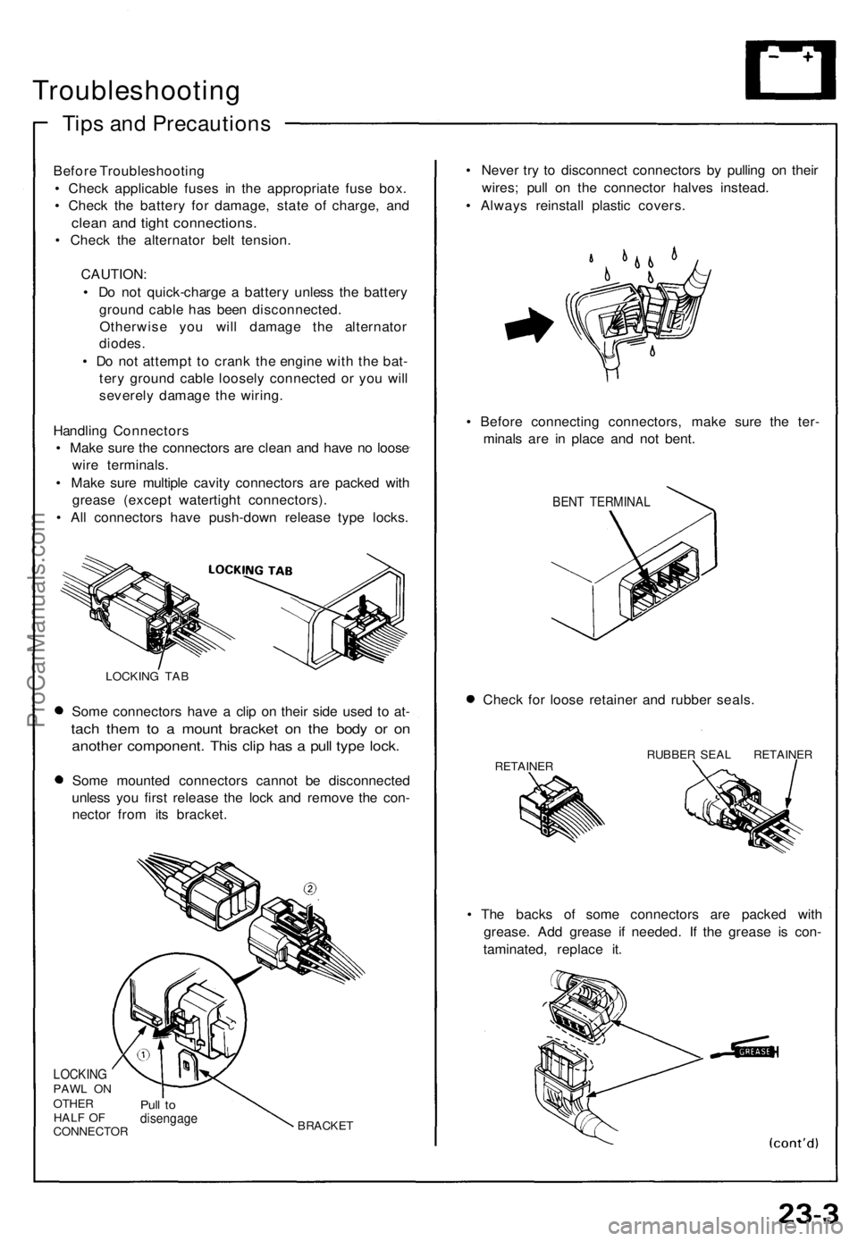
Troubleshooting
Tips and Precautions
Before Troubleshooting
• Check applicable fuses in the appropriate fuse box.
• Check the battery for damage, state of charge, and
clean and tight connections.
• Check the alternator belt tension.
CAUTION:
• Do not quick-charge a battery unless the battery
ground cable has been disconnected.
Otherwise you will damage the alternator
diodes.
• Do not attempt to crank the engine with the bat-
tery ground cable loosely connected or you will
severely damage the wiring.
Handling Connectors
• Make sure the connectors are clean and have no loose
wire terminals.
• Make sure multiple cavity connectors are packed with
grease (except watertight connectors).
• All connectors have push-down release type locks.
LOCKING TAB
Some connectors have a clip on their side used to at-
tach them to a mount bracket on the body or on
another component. This clip has a pull type lock.
Some mounted connectors cannot be disconnected
unless you first release the lock and remove the con-
nector from its bracket.
LOCKING
PAWL ON
OTHER
HALF OF
CONNECTOR
Pull to
disengage
BRACKET
• Never try to disconnect connectors by pulling on their
wires; pull on the connector halves instead.
• Always reinstall plastic covers.
• Before connecting connectors, make sure the ter-
minals are in place and not bent.
BENT TERMINAL
Check for loose retainer and rubber seals.
RETAINER
RUBBER SEAL RETAINER
• The backs of some connectors are packed with
grease. Add grease if needed. If the grease is con-
taminated, replace it.ProCarManuals.com
Page 749 of 1640
- I f th e starte r stil l doe s no t cran k th e engine ,
remov e th e starte r an d diagnos e it s interna l
problems .
- I f th e starte r crank s th e engine , chec k fo r a n
ope n i n th e BLK/WH T wir e an d connector s be -
twee n th e starte r an d ignitio n switch . Chec k th e
ignitio n switch .
On car s wit h automati c transmission , chec k th e
A/ T gea r positio n switc h (neutra l positio n
switch ) an d connector .
O n car s with manua l transmission , chec k th e
starte r cu t relay , clutc h interloc k switc h an d
connectors .
NOTE : Chec k th e No . 2 9 (5 0 A ) fus e an d th e
starte r cu t relay , an d inspec t th e securit y alar m
system .
3 . Chec k fo r wea r o r damage :
Th e starte r shoul d cran k th e engin e smoothl y an d
steadily .
If th e starte r engages , bu t crank s th e engin e er -
ratically , remov e th e starte r motor . Inspec t th e
starter , driv e gea r an d flywhee l rin g gea r fo r
damage .
Check th e driv e gea r overrunnin g clutc h fo r bindin g
or slippin g whe n th e armatur e i s rotated with th e
driv e gea r held . Replac e th e gear s i f damaged .
4 . Chec k crankin g voltag e an d curren t draw :
Voltag e shoul d b e n o les s tha n 8. 5 volts .
Curren t shoul d b e n o mor e tha n 35 0 amperes .
I f voltag e i s to o low , o r curren t dra w to o high ,
chec k for :
• Lo w battery .
• Ope n circui t i n starte r armatur e commutato r
segments .
• Starte r armatur e dragging .
• Shorte d armatur e winding .
• Excessiv e dra g i n engine . 5
. Chec k crankin g rpm :
Engin e spee d durin g crankin g shoul d b e abov e 10 0
rpm .
If spee d i s to o low , chec k for :
Loos e batter y o r starte r terminals .
Excessivel y wor n starte r brushes .
Ope n circui t i n commutato r segments .
Dirt y o r damage d helica l splin e o r driv e gear .
Defectiv e driv e gea r overrunnin g clutch .
6 . Chec k th e starte r disengagement :
Depres s th e clutc h peda l al l th e wa y (M/T ) o r shif t
to positio n (A/T) , tur n th e ignitio n switc h
to "Star t (III) " an d releas e to O N (II) .
The starter drive gea r shoul d disengag e fro m th e
flywhee l rin g gear .
I f th e driv e gea r hang s u p o n th e flywhee l rin g gear ,
check :
• Solenoi d plunge r an d switc h fo r malfunction .
• Driv e gea r assembl y fo r dir t o r damage d over -
runnin g clutch .
ProCarManuals.com
Page 751 of 1640
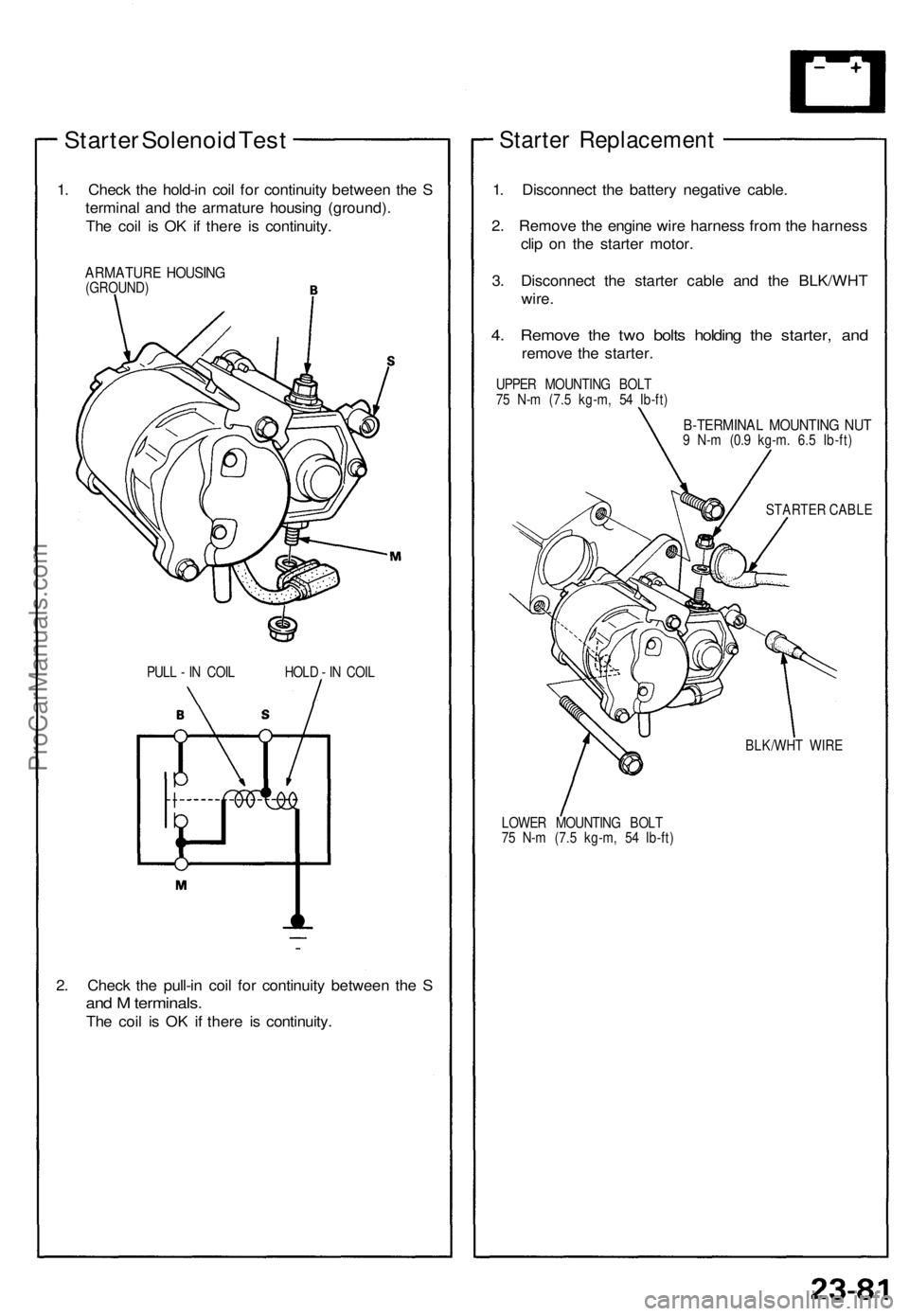
Starter Solenoid Test
1. Check the hold-in coil for continuity between the S
terminal and the armature housing (ground).
The coil is OK if there is continuity.
ARMATURE HOUSING
(GROUND)
PULL - IN COIL HOLD - IN COIL
2. Check the pull-in coil for continuity between the S
and M terminals.
The coil is OK if there is continuity.
Starter Replacement
1. Disconnect the battery negative cable.
2. Remove the engine wire harness from the harness
clip on the starter motor.
3. Disconnect the starter cable and the BLK/WHT
wire.
4. Remove the two bolts holding the starter, and
remove the starter.
UPPER MOUNTING BOLT
75 N-m (7.5 kg-m, 54 Ib-ft)
B-TERMINAL MOUNTING NUT
9 N-m (0.9 kg-m. 6.5 Ib-ft)
STARTER CABLE
LOWER MOUNTING BOLT
75 N-m (7.5 kg-m, 54 Ib-ft)
BLK/WHT WIREProCarManuals.com
Page 760 of 1640
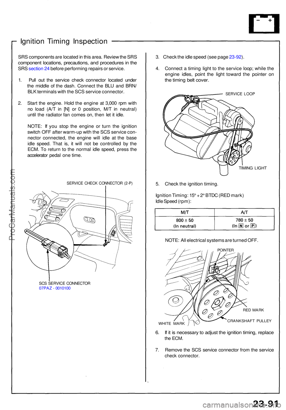
Ignition Timin g Inspectio n
SRS component s ar e locate d in thi s area . Revie w th e SR S
componen t locations , precautions , an d procedure s in th e
SR S sectio n 24 befor e performin g repair s o r service .
1 . Pul l ou t th e servic e chec k connecto r locate d unde r
th e middl e o f th e dash . Connec t th e BL U an d BRN /
BL K terminal s wit h th e SC S servic e connector .
2 . Star t th e engine . Hol d th e engin e a t 3,00 0 rp m wit h
n o loa d (A/ T i n [N ] o r 0 position , M/ T i n neutral )
unti l th e radiato r fa n come s on , the n le t i t idle .
NOTE : I f yo u sto p th e engin e o r tur n th e ignitio n
switc h OF F afte r warm-u p wit h th e SC S servic e con -
necto r connected , th e engin e wil l idl e a t th e bas e
idl e speed . Tha t is , i t wil l no t b e controlle d b y th e
ECM . T o retur n t o th e norma l idl e speed , pres s th e
accelerato r peda l on e time .
SERVIC E CHEC K CONNECTO R (2-P )
SCS SERVIC E CONNECTO R07PAZ - 001010 0
3. Chec k th e idl e spee d (se e pag e 23-92 ).
4 . Connec t a timin g ligh t t o th e servic e loop ; whil e th e
engin e idles , poin t th e ligh t towar d th e pointe r o n
the timin g bel t cover .
SERVIC E LOO P
TIMIN G LIGH T
5. Chec k th e ignitio n timing .
Ignitio n Timing : 15 ° + 2° BTD C (RE D mark )
Idl e Spee d (rpm) :
NOTE : Al l electrica l system s ar e turne d OFF .
POINTE R
WHITE MAR K
RED MAR K
CRANKSHAF T PULLE Y
6. I f i t i s necessar y to adjus t th e ignitio n timing , replac e
the ECM .
7. Remov e th e SC S servic e connecto r fro m th e servic e
check connector .
ProCarManuals.com