1991 ACURA NSX charging
[x] Cancel search: chargingPage 1097 of 1640
Idle Control System
Troubleshooting Flowchart
Alternator (ALT) FR Signal
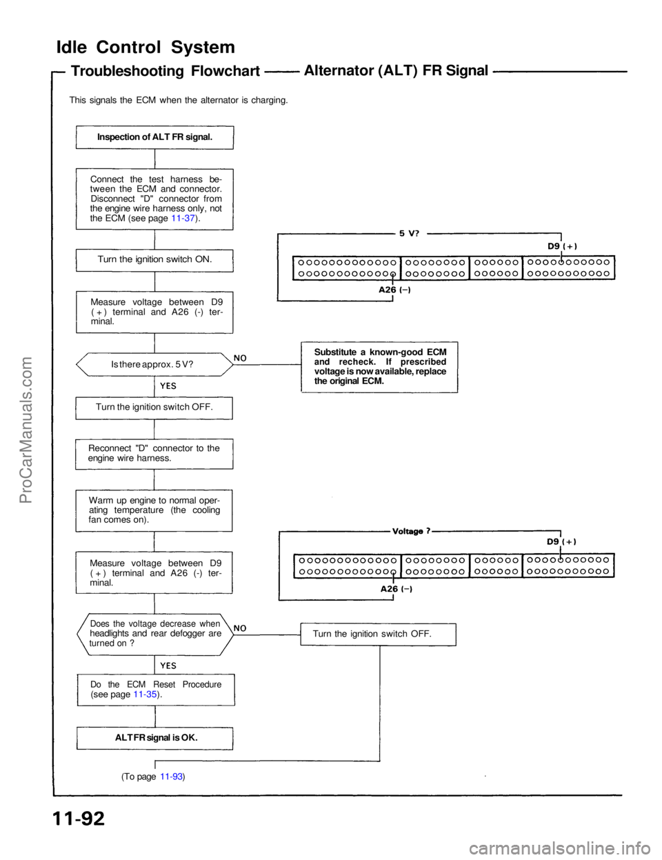
This signals the ECM when the alternator is charging.
Inspection of ALT FR signal.
Connect the test harness be-
tween the ECM and connector.
Disconnect "D" connector from
the engine wire harness only, not
the ECM (see page 11-37).
Turn the ignition switch ON.
Measure voltage between D9 ( + ) terminal and A26 (-) ter-
minal.
Is there approx. 5 V?
Turn the ignition switch OFF.
Reconnect "D" connector to the
engine wire harness.
Warm up engine to normal oper-ating temperature (the cooling
fan comes on).
Measure voltage between D9( + ) terminal and A26 (-) ter-
minal.
Does the voltage decrease when
headlights and rear defogger are
turned on ?
Do the ECM Reset Procedure
(see page 11-35).
ALT FR signal is OK.(To page 11-93) Substitute a known-good ECM
and recheck. If prescribed
voltage is now available, replace
the original ECM.
Turn the ignition switch OFF.ProCarManuals.com
Page 1396 of 1640
Charging System
Alternator Overhaul
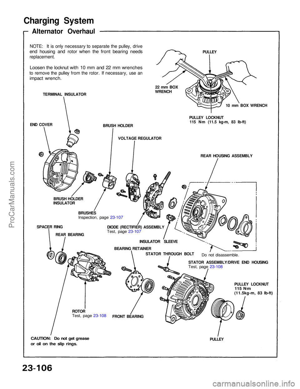
NOTE: It is only necessary to separate the pulley, drive
end housing and rotor when the front bearing needs
replacement.
Loosen the locknut with 10 mm and 22 mm wrenches
to remove the pulley from the rotor. If necessary, use an
impact wrench.
TERMINAL INSULATOR
END COVER BRUSH HOLDER
22 mm BOX
WRENCH
VOLTAGE REGULATOR
BRUSH HOLDER
INSULATOR
SPACER RING
REAR BEARING
BRUSHES
Inspection, page 23-107
DIODE (RECTIFIER) ASSEMBLY
Test, page 23-107
INSULATOR SLEEVE
BEARING RETAINER STATOR THROUGH BOLT
Do not disassemble.
STATOR ASSEMBLY/DRIVE END HOUSING
Test, page 23-108
PULLEY LOCKNUT
115 N .
m
(11.5kg-m, 83 Ib-ft)
PULLEY
FRONT BEARING
ROTOR
Test, page 23-108
CAUTION: Do not get grease
or oil on the slip rings.
PULLEY
10 mm BOX WRENCH
PULLEY LOCKNUT 115 N .
m (11.5 kg-m, 83 Ib-ft)
REAR HOUSING ASSEMBLYProCarManuals.com
Page 1400 of 1640
Gauge Assembly
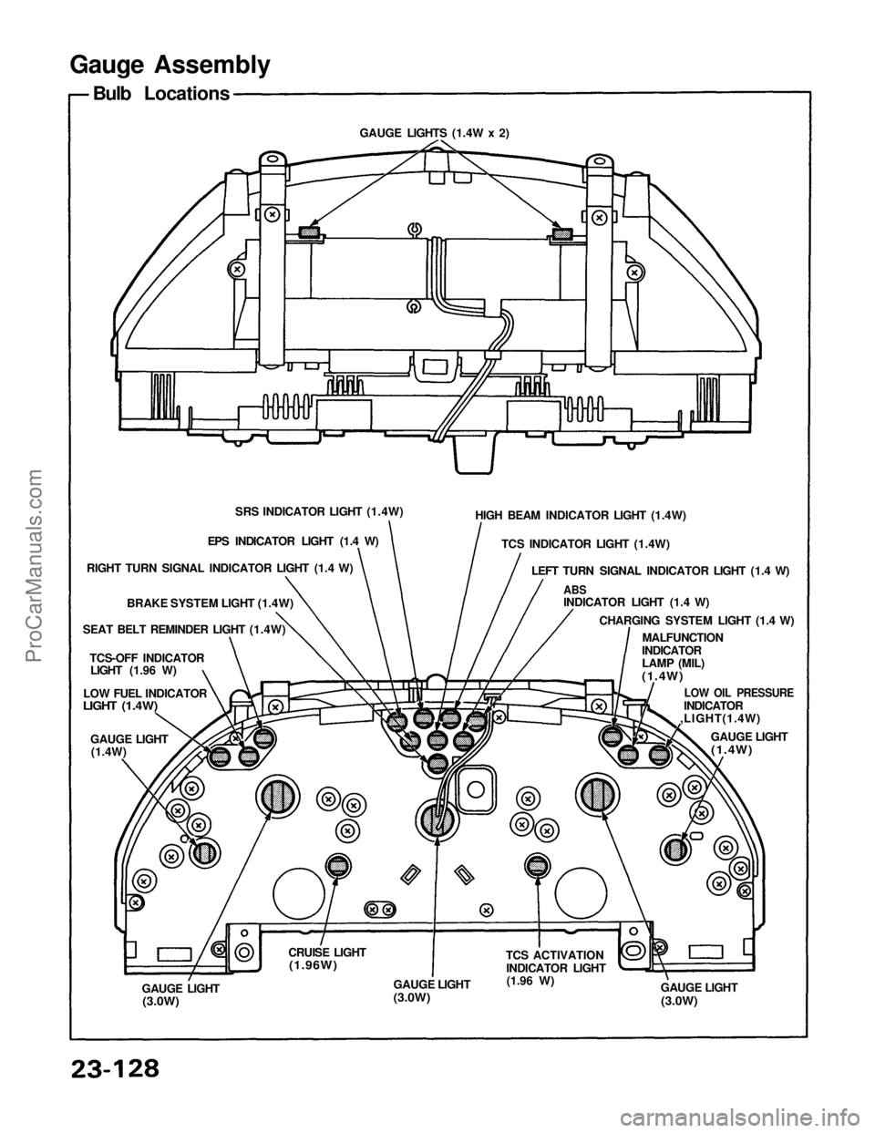
Bulb Locations
SRS INDICATOR LIGHT (1.4W)
EPS INDICATOR LIGHT (1.4 W)
RIGHT TURN SIGNAL INDICATOR LIGHT (1.4 W)
BRAKE SYSTEM LIGHT (1.4W)
SEAT BELT REMINDER LIGHT (1.4W)
TCS-OFF INDICATOR
LIGHT (1.96 W)
LOW FUEL INDICATOR
LIGHT (1.4W)
GAUGE LIGHT
(1.4W)
GAUGE LIGHT
(3.0W)
CRUISE LIGHT
(1.96W)
GAUGE LIGHT
(3.0W)
TCS ACTIVATION
INDICATOR LIGHT
(1.96
W)
GAUGE LIGHT
(3.0W)
GAUGE LIGHT
(1.4W)
LOW OIL PRESSURE
INDICATOR
,LIGHT(1.4W)
MALFUNCTION
INDICATOR
LAMP (MIL)
(1.4W)
CHARGING SYSTEM LIGHT (1.4 W)
ABS
INDICATOR LIGHT (1.4 W)
LEFT TURN SIGNAL INDICATOR LIGHT (1.4 W)
TCS INDICATOR LIGHT (1.4W)
HIGH BEAM INDICATOR LIGHT (1.4W)
GAUGE LIGHTS (1.4W x 2)ProCarManuals.com
Page 1480 of 1640
PGM-FI Control System
System Description
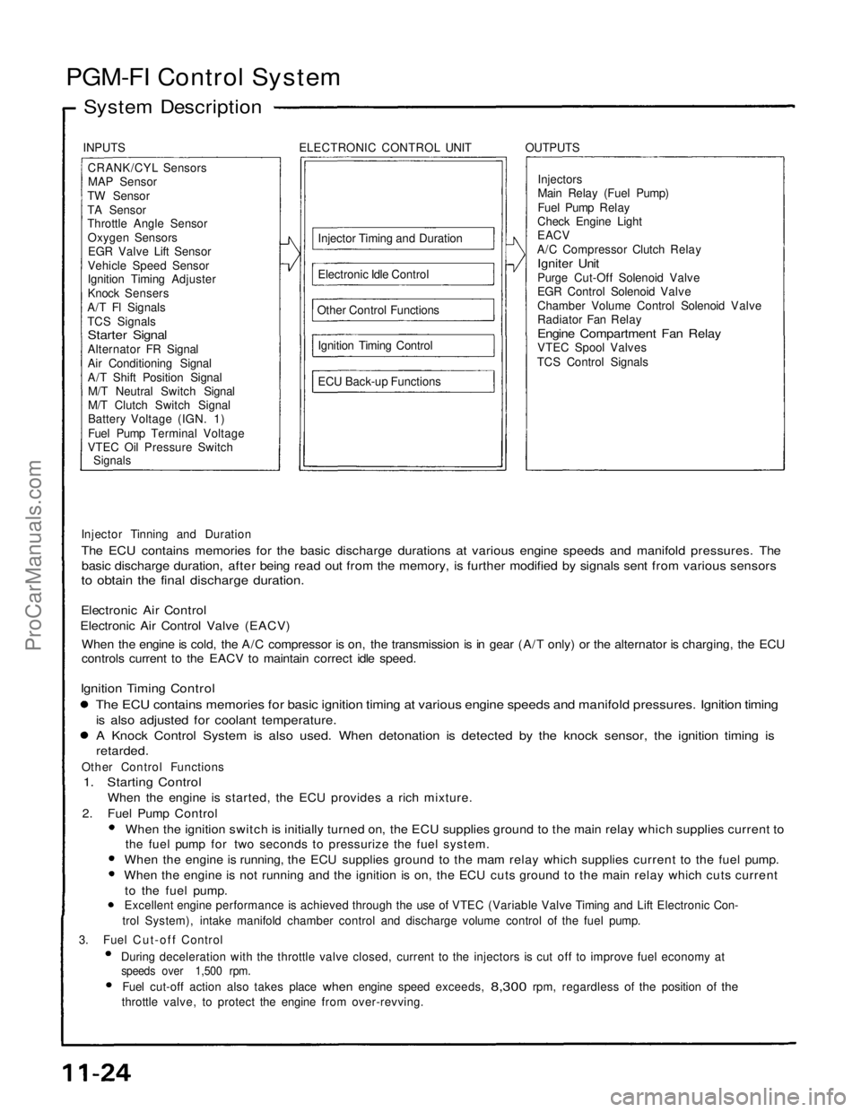
INPUTS ELECTRONIC CONTROL UNIT OUTPUTSCRANK/CYL SensorsMAP Sensor
TW Sensor
TA Sensor
Throttle Angle Sensor Oxygen SensorsEGR Valve Lift Sensor
Vehicle Speed Sensor
Ignition Timing Adjuster
Knock Sensers
A/T Fl Signals
TCS Signals
Starter Signal
Alternator FR Signal
Air Conditioning Signal
A/T Shift Position Signal M/T Neutral Switch Signal
M/T Clutch Switch Signal
Battery Voltage (IGN. 1)
Fuel Pump Terminal Voltage
VTEC Oil Pressure Switch
Signals
Injector Timing and Duration
Electronic Idle Control
Other Control Functions Ignition Timing Control
ECU Back-up Functions Injectors
Main Relay (Fuel Pump)
Fuel Pump Relay
Check Engine Light
EACV
A/C Compressor Clutch Relay
Igniter Unit
Purge Cut-Off Solenoid Valve
EGR Control Solenoid Valve
Chamber Volume Control Solenoid Valve
Radiator Fan Relay
Engine Compartment Fan Relay
VTEC Spool Valves
TCS Control Signals
Injector Tinning and Duration
The ECU contains memories for the basic discharge durations at various engine speeds and manifold pressures. The
basic discharge duration, after being read out from the memory, is further modified by signals sent from various sensors
to obtain the final discharge duration.
Electronic Air Control
Electronic Air Control Valve (EACV)
When the engine is cold, the A/C compressor is on, the transmission is in gear (A/T only) or the alternator is charging, the ECU
controls current to the EACV to maintain correct idle speed.
Ignition Timing Control
The ECU contains memories for basic ignition timing at various engine speeds and manifold pressures. Ignition timing
is also adjusted for coolant temperature.
A Knock Control System is also used. When detonation is detected by the knock sensor, the ignition timing is
retarded.
Other Control Functions
1. Starting Control
When the engine is started, the ECU provides a rich mixture.
2. Fuel Pump Control
When the ignition switch is initially turned on, the ECU supplies ground to the main relay which supplies current to
the fuel pump for two seconds to pressurize the fuel system.
When the engine is running, the ECU supplies ground to the mam relay which supplies current to the fuel pump.
When the engine is not running and the ignition is on, the ECU cuts ground to the main relay which cuts current
to the fuel pump.
Excellent engine performance is achieved through the use of VTEC (Variable Valve Timing and Lift Electronic Con-
trol System), intake manifold chamber control and discharge volume control of the fuel pump.
3. Fuel Cut-off Control During deceleration with the throttle valve closed, current to the injectors is cut off to improve fuel economy at
speeds over 1,500 rpm.
Fuel cut-off action also takes place
when
engine speed exceeds,
8,300
rpm, regardless
of the
position
of the
throttle valve, to protect the engine from over-revving.ProCarManuals.com
Page 1489 of 1640
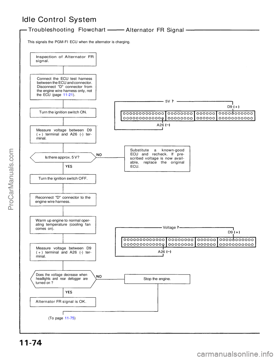
Idle Control System
Troubleshooting Flowchart Alternator FR Signal
This signals the PGM-FI ECU when the alternator is charging.
Inspection of Alternator FR
signal.
Connect the ECU test harness
between the ECU and connector.
Disconnect "D" connector from
the engine wire harness only, not
the ECU (page 11-21).
Turn the ignition switch ON.
Measure voltage between D9 ( + ) terminal and A26 (-) ter-
minal.
Is there approx. 5 V?
5V
D9
A26
Substitute a known-good ECU and recheck. If pre-
scribed voltage is now avail-
able, replace the original ECU.
Turn the ignition switch OFF.
Reconnect "D" connector to the
engine wire harness.
Warm up engine to normal oper-
ating temperature (cooling fan
comes on).
Voltage
D9
A26
Measure voltage between D9
( + ) terminal and A26 (-) ter-
minal.
Stop the engine.
Does the voltage decrease when
headlights and rear defogger are
turned on ?
Alternator FR signal is OK.
(To page 11-75)ProCarManuals.com
Page 1569 of 1640
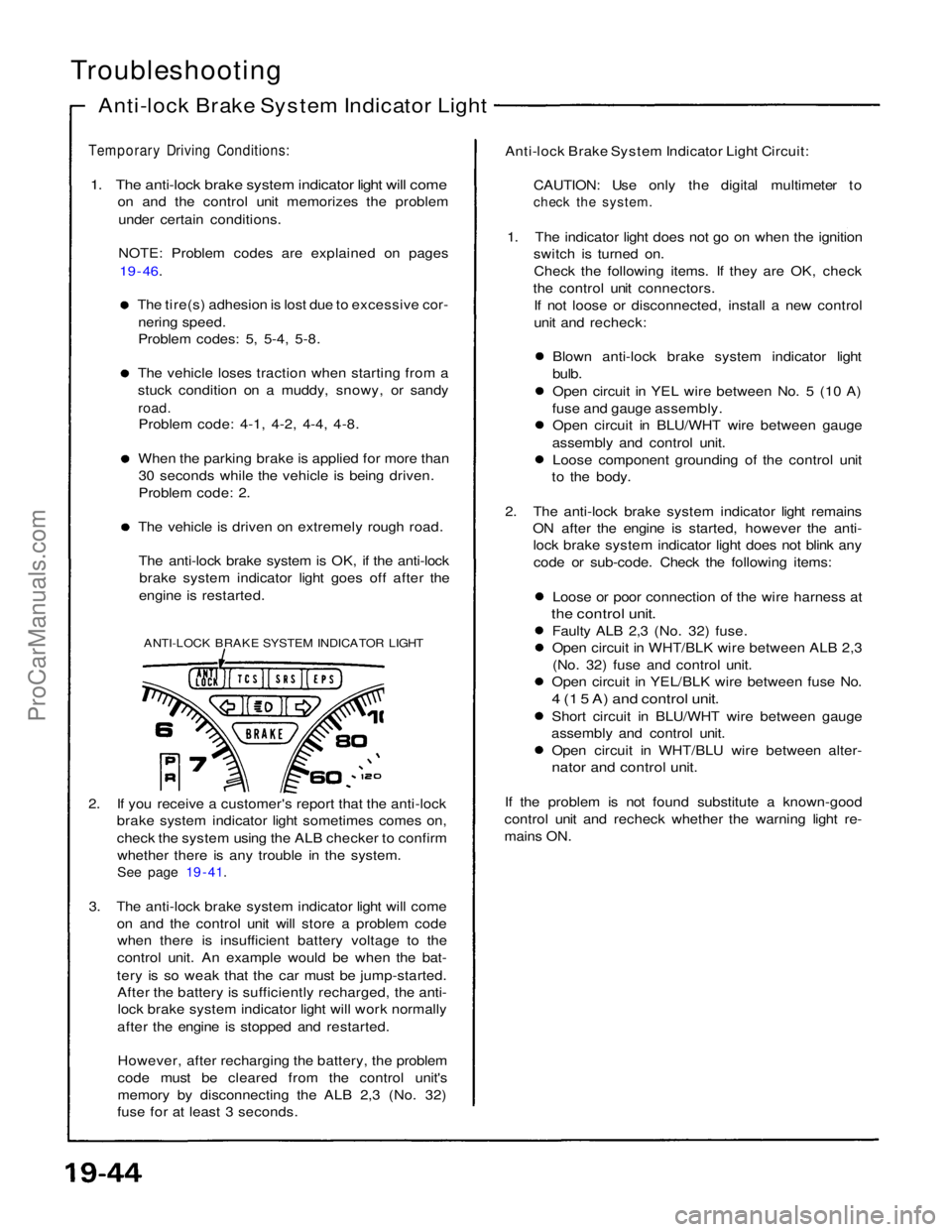
Troubleshooting
Anti-lock Brake System Indicator Light
Temporary Driving Conditions:
1. The anti-lock brake system indicator light will come
on and the control unit memorizes the problem
under certain conditions.
NOTE: Problem codes are explained on pages
19 - 46.
The tire(s) adhesion is lost due to excessive cor-
nering speed.
Problem codes: 5, 5-4, 5-8. The vehicle loses traction when starting from a
stuck condition on a muddy, snowy, or sandy
road.
Problem code: 4-1, 4-2, 4-4, 4-8. When the parking brake is applied for more than
30 seconds while the vehicle is being driven.
Problem code: 2. The vehicle is driven on extremely rough road.
The anti-lock brake system is OK, if the anti-lock brake system indicator light goes off after the
engine is restarted.
ANTI-LOCK BRAKE SYSTEM INDICATOR LIGHT
2. If you receive a customer's report that the anti-lock brake system indicator light sometimes comes on,
check the system using the ALB checker to confirm
whether there is any trouble in the system.
See page 19 - 41.
3. The anti-lock brake system indicator light will come on and the control unit will store a problem codewhen there is insufficient battery voltage to the
control unit. An example would be when the bat-
tery is so weak that the car must be jump-started. After the battery is sufficiently recharged, the anti-lock brake system indicator light will work normally
after the engine is stopped and restarted.
However, after recharging the battery, the problem
code must be cleared from the control unit's
memory by disconnecting the ALB 2,3 (No. 32)
fuse for at least 3 seconds. Anti-lock Brake System Indicator Light Circuit:
CAUTION: Use only the digital multimeter to
check the system.
1. The indicator light does not go on when the ignition switch is turned on.
Check the following items. If they are OK, check
the control unit connectors. If not loose or disconnected, install a new control
unit and recheck:
Blown anti-lock brake system indicator light
bulb.
Open circuit in YEL wire between No. 5 (10 A)
fuse and gauge assembly. Open circuit in BLU/WHT wire between gauge
assembly and control unit. Loose component grounding of the control unit
to the body.
2. The anti-lock brake system indicator light remains ON after the engine is started, however the anti-lock brake system indicator light does not blink any
code or sub-code. Check the following items:
Loose or poor connection of the wire harness at
the control unit.
Faulty ALB 2,3 (No. 32) fuse.
Open circuit in WHT/BLK wire between ALB 2,3(No. 32) fuse and control unit.
Open circuit in YEL/BLK wire between fuse No.
4 (1 5 A) and control unit.
Short circuit in BLU/WHT wire between gauge
assembly and control unit. Open circuit in WHT/BLU wire between alter-
nator and control unit.
If the problem is not found substitute a known-good
control unit and recheck whether the warning light re-
mains ON.ProCarManuals.com