Page 766 of 1640
Charging Syste m
Componen t Locatio n Inde x
CHARGIN G SYSTE M LIGH T(Built int o th e gaug e assembly )Test, pag e 23-10 0
BATTER YTest, pag e 23-6 8
ALTERNATO R BEL TAdjustment , pag e 23-10 9
ALTERNATO R• Alternato r an d Regulato r Test , pag e 23-10 2
• Replacement , pag e 23-10 5
• Overhaul , pag e 23-10 6
ProCarManuals.com
Page 767 of 1640

Charging Syste m
Troubleshootin g
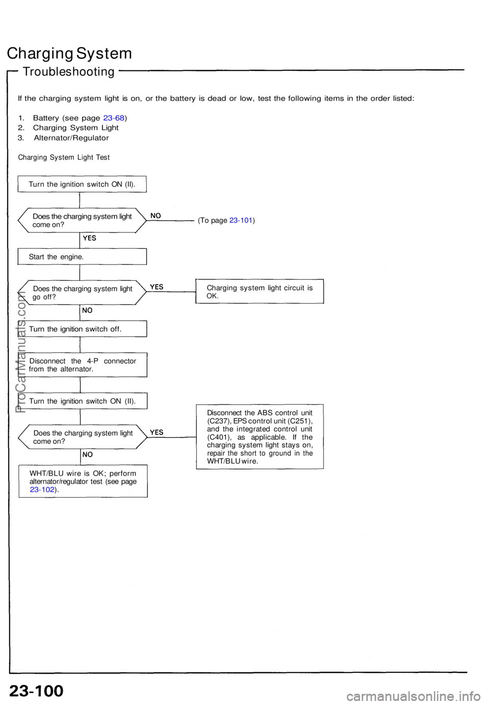
If th e chargin g syste m ligh t i s on , o r th e batter y i s dea d o r low , tes t th e followin g item s i n th e orde r listed :
1. Batter y (se e pag e 23-68 )
2. Chargin g Syste m Ligh t
3. Alternator/Regulato r
Charging Syste m Ligh t Tes t
Does th e chargin g syste m ligh tcom e on ?
Star t th e engine .
Doe s th e chargin g syste m ligh t
go off ?
Turn th e ignitio n switc h off .
Disconnec t th e 4- P connecto r
fro m th e alternator .
Tur n th e ignitio n switc h O N (II) .
WHT/BL U wir e i s OK ; perfor m
alternator/regulato r tes t (se e pag e
23-102 ).
Doe s th e chargin g syste m ligh t
com e on ? (T
o pag e 23-101 )
Chargin g syste m ligh t circui t i s
OK .
Disconnec t th e AB S contro l uni t
(C237) , EP S contro l uni t (C251) ,
an d th e integrate d contro l uni t
(C401) , a s applicable . I f th e
chargin g syste m ligh t stay s on ,
repai r th e shor t t o groun d i n th eWHT/BL U wire .
Tur
n th e ignitio n switc h O N (II) .
ProCarManuals.com
Page 769 of 1640
Charging System
Troubleshooting
Alternator/Regulator Test
Use the SUN VAT-40 (or equivalent) tester.
2. Attach the negative tester cable and the voltmeter
negative lead to the top of the intake manifold.
LOAD ADJUSTER
(CARBON PILE)
FULL FIELD
LEAD (BLU)
VOLTMETER
NEGATIVE
LEAD (BLK)
VOLT
SELECTOR
FIELD
SELECTOR
INDUCTIVE
PICK-UP
(GRN)
POSITIVE
CABLE (RED)
NEGATIVE
CABLE (BLK)
VOLTMETER
POSITIVE
LEAD (RED)
1. Attach the positive tester cable and the voltmeter
positive lead to the jump start terminal in the
engine compartment fuse/relay box.
POSITIVE CABLE
VOLTMETER
POSITIVE LEAD
JUMP
START
TERMINAL
- ENGINE COMPARTMENT
FUSE/RELAY BOX
VOLTMETER
NEGATIVE LEAD
NEGATIVE CABLE
NEGATIVE MARK
3. Attach the inductive pick-up to the B terminal wire
of the alternator with its arrow pointing away from
the terminal.
NOTE: The arrow must point away from the B
terminal.
INDUCTIVE PICK-UP
ARROW
ALTERNATOR
B TERMINAL
ALTERNATOR
TEST SELECTOR
SWITCHProCarManuals.com
Page 770 of 1640
NOTE: B e sur e th e batter y is sufficientl y charge d
(see pag e 23-68 ).
Connec t th e Su n VAT-4 0 (se e
pag e 23-102 ) an d tur n th e selec -
to r switc h t o positio n 1 (star -
ting) .
Star t th e engin e an d le t i t idl e un -
ti l i t reache s norma l operatin g
temperature .
Raise th e engin e spee d t o 2,00 0rpm an d hol d i t there .
Is th e voltag e ove r 15. 1 V ?
Releas e th e accelerato r peda l
and le t th e engin e idle .
Mak e sur e al l accessorie s ar eturne d off . Tur n th e selecto rswitch t o positio n 2 (charging) .
Remove th e inductiv e pick-u p
an d zer o th e ammeter .
Attach th e inductiv e pick-u p t oth e B termina l wir e o f th ealternato r wit h it s arro w pointin gaway fro m th e terminal .
Rais e th e engin e spee d t o 2,00 0
rpm an d hol d i t there .
Is th e voltag e les s tha n 13. 9 V ?
(T o pag e 23-104 ) Replac
e th e voltag e regulator .
Tes t th e batter y (se e pag e23-68).
ProCarManuals.com
Page 771 of 1640

Charging Syste m
Troubleshootin g
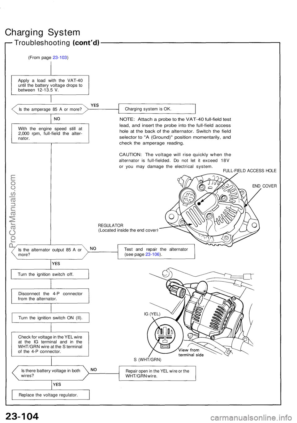
(From pag e 23-103 )
Appl y a loa d wit h th e VAT-4 0
unti l th e batter y voltag e drop s t o
betwee n 12-13. 5 V .
Is th e amperag e 8 5 A or more ?
With th e engin e spee d stil l a t2,00 0 rpm , full-fiel d th e alter -nator.
Turn th e ignitio n switc h off .
Disconnec t th e 4- P connecto r
fro m th e alternator .
Tur n th e ignitio n switc h O N (II) .
Chec k fo r voltag e in th e YE L wir e
a t th e I G termina l an d i n th e
WHT/GR N wir e a t th e S termina l
o f th e 4- P connector .
I s ther e batter y voltag e in bot h
wires ?
Chargin g syste m is OK .
NOTE : Attac h a prob e to th e VAT-4 0 full-fiel d tes t
lead , an d inser t th e prob e int o th e full-fiel d acces s
hole a t th e bac k o f th e alternator . Switc h th e fiel d
selecto r t o " A (Ground) " positio n momentarily , an d
chec k th e amperag e reading .
CAUTION : Th e voltag e wil l ris e quickl y whe n th e
alternato r i s full-fielded . D o no t le t i t excee d 18 V
o r yo u ma y damag e th e electrica l system .
FULL-FIEL D ACCES S HOL E
END COVE R
REGULATO R(Located insid e th e en d cove r
I s th e alternato r outpu t 8 5 A or
more ?Test an d repai r th e alternato r
(se e pag e 23-106 ).
IG (YEL )
S (WHT/GRN )
Repair ope n in th e YE L wir e o r th eWHT/GR N wire .
Replac e th e voltag e regulator .
ProCarManuals.com
Page 773 of 1640
Charging Syste m
Alternato r Overhau l
NOTE: I t i s onl y necessar y t o separat e th e pulley , driv e
end housin g an d roto r whe n th e fron t bearin g need s
replacement .
Loosen th e locknu t wit h 1 0 m m an d 2 2 m m wrenche s
to remov e th e pulle y fro m th e rotor . I f necessary , us e a n
impac t wrench .
TERMINA L INSULATO R
PULLEY
22 m m BO XWRENC H
10 m m BO X WRENC H
EN D COVE R PULLE
Y LOCKNU T
11 5 N- m (11. 5 kg-m , 8 3 Ib-ft )
REA R HOUSIN G ASSEMBLY
BRUS H HOLDE R
INSULATO R
BRUSHE S
Inspection , pag e 23-10 7
SPACE R RIN G
REA R BEARIN GDIOD
E (RECTIFIER ) ASSEMBL YTest, pag e 23-10 7
INSULATO R SLEEV E
BEARIN G RETAINE R
STATO R THROUG H BOL T
Do no t disassemble .
STATOR ASSEMBLY/DRIV E EN D HOUSIN GTest, pag e 23-10 8
PULLE Y LOCKNU T115 N- m(11. 5 kg-m , 8 3 Ib-ft )
ROTO RTest, pag e 23-10 8
CAUTION : D o no t ge t greas e
o r oi l o n th e sli p rings .
FRONT BEARIN G
PULLEY
BRUSH HOLDE R
VOLTAG E REGULATO R
ProCarManuals.com
Page 775 of 1640
Charging System
Rotor Slip Ring Test
1. Check that there is continuity between the slip rings.
2. Check that there is no continuity between the slip
rings and the rotor or rotor shaft.
ROTOR SHAFT
SLIP RINGS
ROTOR
3. If the rotor fails either continuity check, replace the
alternator.
Stator Test
1. Check that there is continuity between each pair of
leads.
2. Check that there is no continuity between each lead
and the coil core.
LEADS
COIL CORE
3. If the coil fails either continuity check, replace the
alternator.ProCarManuals.com
Page 789 of 1640
Gauge Assembly
Bulb Locations
GAUGE LIGHTS (1.4W x 2)
SRS INDICATOR LIGHT (1.4 W)
RIGHT TURN SIGNAL INDICATOR LIGHT (1.4 W)
EPS INDICATOR LIGHT (1.4 W)
BRAKE SYSTEM LIGHT (1.4 W)
SEAT BELT REMINDER LIGHT (1.4 W)
TCS INDICATOR
LIGHT (1.96 W)
LOW FUEL INDICATOR
LIGHT (1.4 W)
GAUGE LIGHT
(1.4
W)
HIGH BEAM INDICATOR LIGHT (1.4 W)
LEFT TURN SIGNAL INDICATOR LIGHT (1.4 W)
ABS
INDICATOR LIGHT (1.4 W)
CHARGING SYSTEM LIGHT (1.4 W)
MALFUNCTION
INDICATOR
LAMP (MIL)
(1.4W)
LOW OIL PRESSURE
INDICATOR
LIGHT (1.4 W)
GAUGE LIGHT
(1.4
W)
GAUGE LIGHT
(3.0
W)
GAUGE LIGHT
(3.0
W)
GAUGE LIGHT
(3.0
W)
CRUISE INDICATOR LIGHT
(1.96
W)ProCarManuals.com