Page 1107 of 1640
6. Turn the ignition switch OFF.
7. Reconnect the 2P connector on the IAC valve, then
remove CLOCK fuse in the under-hood fuse/relay
box for 10 seconds to reset ECM.
8. Restart and idle the engine with no-load conditions
in which the headlights, blower fan, rear defogger,
cooling fan, and air conditioner are not operating
for one minute, then check the idle speed.
Idle speed should be:
M/T
A/T
800
50 rpm
750
50 rpm
(in or range)ProCarManuals.com
Page 1138 of 1640

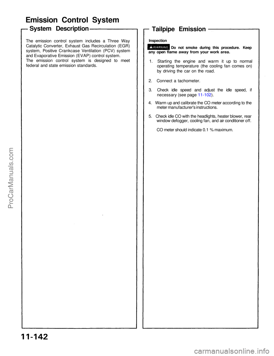
Emission Contro l Syste m
The emissio n contro l syste m include s a Thre e Wa y
Catalyti c Converter , Exhaus t Ga s Recirculatio n (EGR )
system , Positiv e Crankcas e Ventilatio n (PCV ) syste m
an d Evaporativ e Emissio n (EVAP ) contro l system .
Th e emissio n contro l syste m i s designe d t o mee t
federa l an d stat e emissio n standards .
Tailpipe Emissio n
1. Startin g th e engin e an d war m i t u p t o norma l
operatin g temperatur e (th e coolin g fa n come s on )
b y drivin g th e ca r o n th e road .
2 . Connec t a tachometer .
3 . Chec k idl e spee d an d adjus t th e idl e speed , i f
necessar y (se e pag e 11-102 ).
4 . War m up an d calibrat e th e C O mete r accordin g to th e
mete r manufacturer' s instructions .
5 . Chec k idl e C O wit h th e headlights , heate r blower , rea r
windo w defogger , coolin g fan , an d ai r conditione r off .
C O mete r shoul d indicat e 0. 1 % maximum .
System Descriptio n
Do no t smok e durin g thi s procedure . Kee pany ope n flam e awa y fro m you r wor k area .
Inspectio n
ProCarManuals.com
Page 1428 of 1640

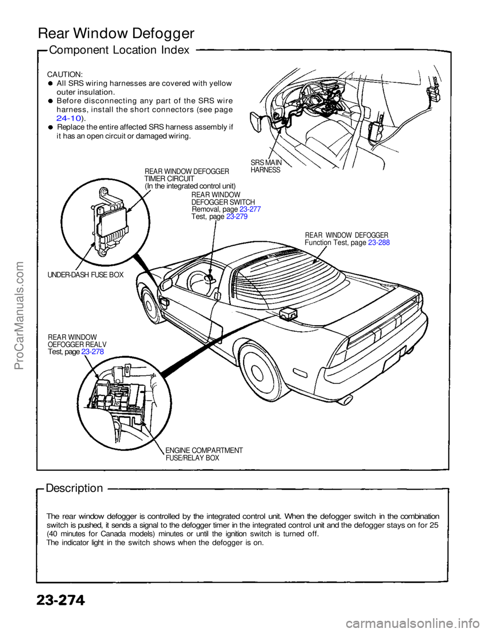
Rear Window Defogger
Component Location Index
CAUTION:
Al
l
SRS wiring harnesses are covered with yellow
outer insulation.
Befor
e
disconnecting any part of the SRS wire
harness
,
install the short connectors (see page
24-10).
Replac
e
the entire affected SRS harness assembly if
it
has an open circuit or damaged wiring.
REA
R
WINDOW DEFOGGERTIME
R
CIRCUIT(I
n
the integrated control unit)
SRS MAIN
HARNESS
REA
R
WINDOWDEFOGGE
R
SWITCHRemoval
,
page 23-277
Test, page 23-279
REAR WINDOW DEFOGGER
Functio
n
Test, page 23-288
UNDER-DASH FUSE BOX
REA
R
WINDOWOEFOGGE
R
REALV
Test, page 23-278
ENGIN
E
COMPARTMENT
FUSE/RELAY BOX
Description
The rear window defogger is controlled by the integrated control unit. When the defogger switch in the combination
switch is pushed, it sends a signal to the defogger timer in the integrated control unit and the defogger stays on for 25
(40 minutes for Canada models) minutes or until the ignition switch is turned off.
The indicator light in the switch shows when the defogger is on.ProCarManuals.com
Page 1430 of 1640

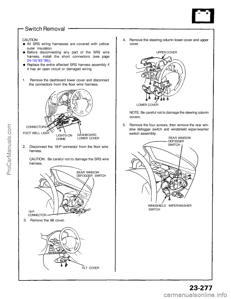
Switch Removal
CAUTION: All SRS wiring harnesses are covered with yellow
outer insulation. Before disconnecting any part of the SRS wire
harness, install the short connectors (see page
24-10('93-'96)). Replace the entire affected SRS harness assembly if
it has an open circuit or damaged wiring.
1. Remove the dashboard tower cover and disconnect
the connectors from the floor wire harness.
CONNECTORS
FOOT WELL LIGHT LIGHTS-ON
CHIME
DASHBOARD
LOWER COVER
2. Disconnect the 18-P connector from the floor wire
harness.
CAUTION: Be careful not to damage the SRS wire
harness.
BEAR WINDOW
DEFOGGER SWITCH
18-P
CONNECTOR
3.
Remove
the
tilt
cover.
TILT COVER
4. Remove the steering column lower cover and upper
cover.
UPPER COVER
LOWER COVER
NOTE: Be careful not to damage the steering column
covers.
5. Remove the four screws, then remove the rear win- dow defogger switch and windshield wiper/washer
switch assembly.
REAR WINDOW
DEFOGGER
SWITCH
WINDSHIELD WIPER/WASHER SWITCHProCarManuals.com
Page 1431 of 1640
Rear Window Defogger
Switch Light Bulb Replacement
1. Remove the steering column lower and upper covers.
2. Remove the four screws from the combination
switch.
3. Remove the rear window defogger switch (see previous page).
4. Remove the rear window defogger switch bulbs.
BULBS (0.91 W)
REAR WINDOW
DEFOGGER SWITCH Relay Test
1. Remove the defogger relay in the engine compart- ment fuse/relay box.
2. There should be continuity between the C and D terminals.
3. There should be continuity between the A and B terminals when power and ground are connected to
the C and D terminals.
There should be no continuity when power isdisconnected.ProCarManuals.com
Page 1489 of 1640
Idle Control System
Troubleshooting Flowchart Alternator FR Signal
This signals the PGM-FI ECU when the alternator is charging.
Inspection of Alternator FR
signal.
Connect the ECU test harness
between the ECU and connector.
Disconnect "D" connector from
the engine wire harness only, not
the ECU (page 11-21).
Turn the ignition switch ON.
Measure voltage between D9 ( + ) terminal and A26 (-) ter-
minal.
Is there approx. 5 V?
5V
D9
A26
Substitute a known-good ECU and recheck. If pre-
scribed voltage is now avail-
able, replace the original ECU.
Turn the ignition switch OFF.
Reconnect "D" connector to the
engine wire harness.
Warm up engine to normal oper-
ating temperature (cooling fan
comes on).
Voltage
D9
A26
Measure voltage between D9
( + ) terminal and A26 (-) ter-
minal.
Stop the engine.
Does the voltage decrease when
headlights and rear defogger are
turned on ?
Alternator FR signal is OK.
(To page 11-75)ProCarManuals.com
Page 1498 of 1640

Idle Control System
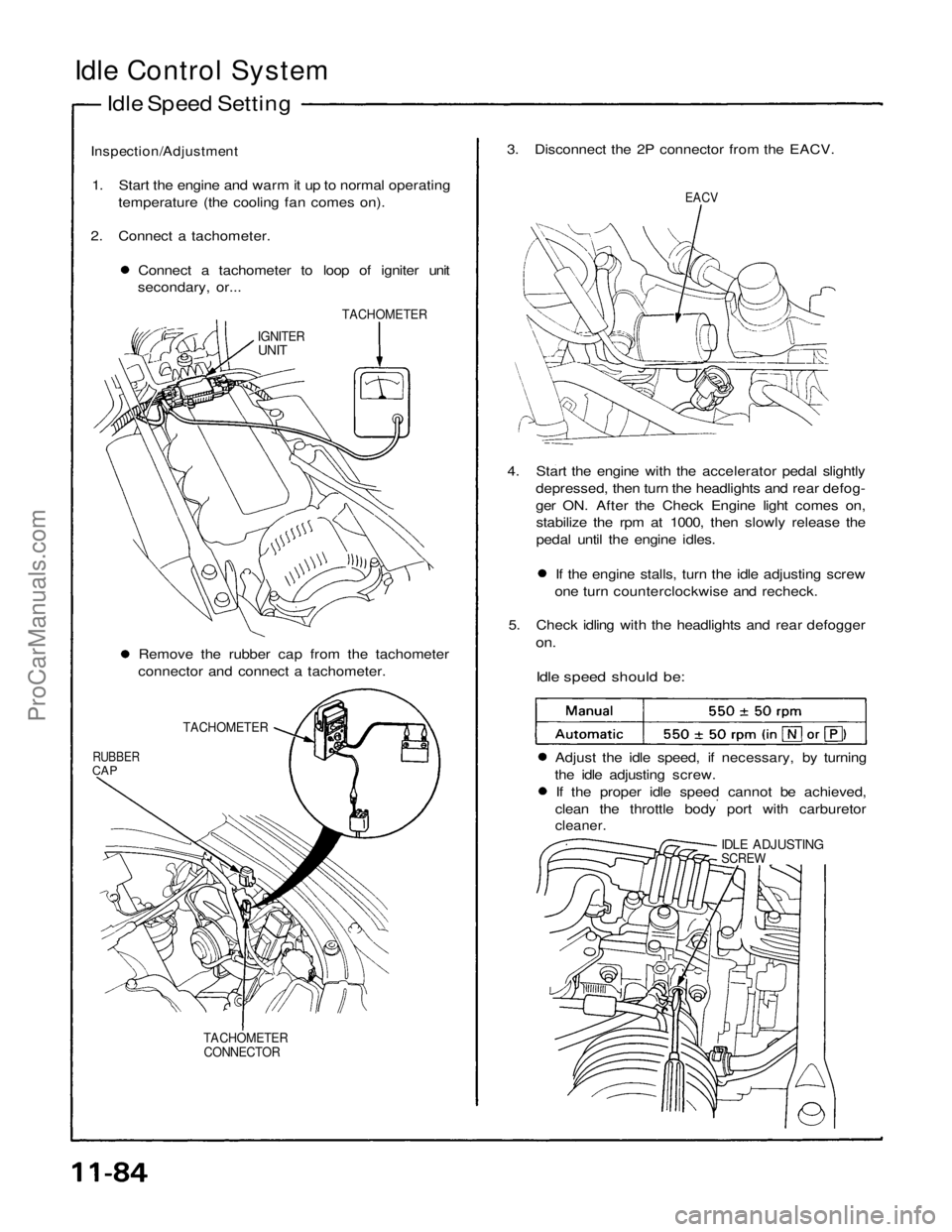
Idle Speed Setting
Inspection/Adjustment
1. Start the engine and warm it up to normal operating temperature (the cooling fan comes on).
2. Connect a tachometer. Connect a tachometer to loop of igniter unit
secondary, or... 3. Disconnect the 2P connector from the EACV.
EACV
TACHOMETER
IGNITER
UNIT
4. Start the engine with the accelerator pedal slightlydepressed, then turn the headlights and rear defog-
ger ON. After the Check Engine light comes on,stabilize the rpm at 1000, then slowly release the
pedal until the engine idles. If the engine stalls, turn the idle adjusting screw
one turn counterclockwise and recheck.
5. Check idling with the headlights and rear defogger
on.
Idle speed should be:
Remove the rubber cap from the tachometer
connector and connect a tachometer.
TACHOMETER
RUBBER
CAP
Adjust the idle speed, if necessary, by turning
the idle adjusting screw. If the proper idle speed cannot be achieved,
clean the throttle body port with carburetor
cleaner.
IDLE ADJUSTING
SCREW
TACHOMETER CONNECTORProCarManuals.com
Page 1499 of 1640
6. Turn the ignition switch OFF.
7. Reconnect the 2P connector on the EACV, then
remove CLOCK fuse in the under-hood fuse/relay
box for 10 seconds to reset ECU.
8. Restart and idle the engine with no-load conditions
in which the headlights, blower fan, rear defogger,
cooling fan, and air conditioner are not operating
for one minute, then check the idle speed.
Idle speed should be:ProCarManuals.com