Page 238 of 1640
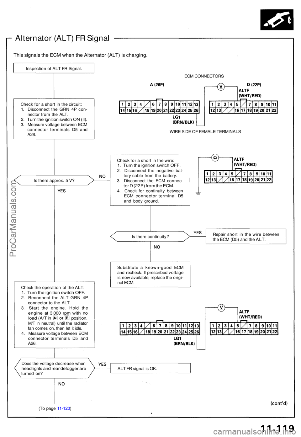
Alternator (ALT ) F R Signa l
This signal s th e EC M whe n th e Alternato r (ALT ) i s charging .
Inspection o f AL T F R Signal .
ECM CONNECTOR S
WIR E SID E O F FEMAL E TERMINAL S
Chec k fo r a shor t i n th e wire :
1. Tur n th e ignitio n switc h OFF .2. Disconnec t th e negativ e bat -
ter y cabl e fro m th e battery .
3 . Disconnec t th e EC M connec -
tor D (22P ) fro m th e ECM .4. Chec k fo r continuit y betwee n
EC M connecto r termina l D 5
an d bod y ground .
I
s ther e approx . 5 V ?
Chec
k fo r a shor t i n th e circuit :
1 . Disconnec t th e GR N 4 P con -
necto r fro m th e ALT .
2. Tur n th e ignitio n switc h O N (II) .3. Measur e voltag e betwee n EC M
connecto r terminal s D 5 an d
A26 .
Is ther e continuity ? Repai
r shor t i n th e wir e betwee nthe EC M (D5 ) and th e ALT .
Substitut e a known-goo d EC M
an d recheck . I f prescribe d voltag e
i s no w available , replac e th e origi -
nal ECM .Chec k th e operatio n o f th e ALT :1. Tur n th e ignitio n switc h OFF .2. Reconnec t th e AL T GR N 4 P
connecto r t o th e ALT .
3 . Star t th e engine . Hol d th e
engin e a t 3,00 0 rp m wit h n oloa d (A/ T in position ,M/T in neutral ) unti l th e radiato r
fa n come s on , the n le t i t idle .
4 . Measur e voltag e betwee n EC M
connecto r terminal s D 5 an d
A26.
Doe s th e voltag e decreas e whe nhead light s an d rea r defogge r ar eturne d on ? AL
T F R signa l i s OK .
(T o pag e 11-120 )
ProCarManuals.com
Page 247 of 1640
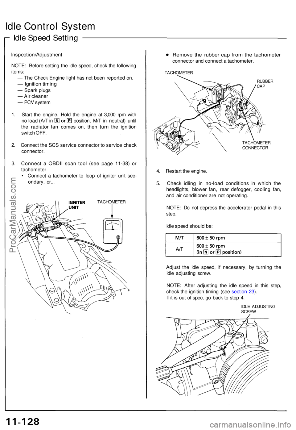
Idle Contro l Syste m
Idle Spee d Settin g
Inspection/Adjustmen t
NOTE: Befor e settin g th e idl e speed , chec k th e followin g
items :
— Th e Chec k Engin e ligh t ha s no t bee n reporte d on .
— Ignitio n timin g
— Spar k plug s
— Ai r cleane r
— PC V syste m
1 . Star t th e engine . Hol d th e engin e a t 3,00 0 rp m wit h
no loa d (A/ T in position , M/ T in neutral ) unti l
th e radiato r fa n come s on , the n tur n th e ignitio n
switc h OFF .
2 . Connec t th e SC S servic e connecto r t o servic e chec k
connector .
3. Connec t a OBDI I sca n too l (se e pag e 11-38 ) o r
tachometer .
• Connec t a tachomete r t o loo p o f ignite r uni t sec -
ondary , or.. .
TACHOMETE R
Remove th e rubbe r ca p fro m th e tachomete r
connector an d connec t a tachometer .
TACHOMETE R
RUBBERCAP
TACHOMETE RCONNECTOR
4. Restar t th e engine .
5 . Chec k idlin g i n no-loa d condition s i n whic h th e
headlights , blowe r fan , rea r defogger , coolin g fan ,
an d ai r conditione r ar e no t operating .
NOTE : D o no t depres s th e accelerato r peda l i n thi s
step .
Idl e spee d shoul d be :
Adjus t th e idl e speed , i f necessary , b y turnin g th e
idl e adjustin g screw .
NOTE : Afte r adjustin g th e idl e spee d i n thi s step ,
chec k th e ignitio n timin g (se e sectio n 23 ).
I f i t i s ou t o f spec , g o bac k t o ste p 4 .
IDL E ADJUSTIN GSCREW
ProCarManuals.com
Page 276 of 1640
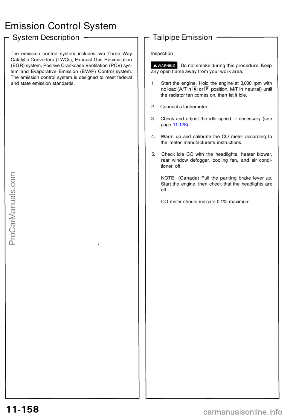
Emission Contro l Syste m
System Descriptio n
The emissio n contro l syste m include s tw o Thre e Wa y
Catalyti c Converter s (TWCs) , Exhaus t Ga s Recirculatio n
(EGR ) system , Positiv e Crankcas e Ventilatio n (PCV ) sys -
te m an d Evaporativ e Emissio n (EVAP ) Contro l system .
Th e emissio n contro l syste m is designe d t o mee t federa l
an d stat e emissio n standards .
Tailpipe Emissio n
Inspectio n
Do no t smok e durin g thi s procedure . Kee p
an y ope n flam e awa y fro m you r wor k area .
1 . Star t th e engine . Hol d th e engin e a t 3,00 0 rp m wit h
no loa d (A/ T in position , M/ T in neutral ) unti l
the radiato r fa n come s on , the n le t i t idle .
2 . Connec t a tachometer .
3 . Chec k an d adjus t th e idl e speed , i f necessar y (se e
pag e 11-128 ).
4 . War m u p an d calibrat e th e C O mete r accordin g t o
th e mete r manufacturer' s instructions .
5 . Chec k idl e C O wit h th e headlights , heate r blower ,
rea r windo w defogger , coolin g fan , an d ai r condi -
tione r off .
NOTE : (Canada ) Pul l th e parkin g brak e leve r up .
Star t th e engine , the n chec k tha t th e headlight s ar e
off.
CO mete r shoul d indicat e 0.1 % maximum .
ProCarManuals.com
Page 591 of 1640
Rear Windo w
Installatio n
18. Us e suctio n cup s t o hol d th e rea r windo w ove r th e
opening , alig n i t wit h th e alignmen t mark s mad e in
ste p 1 1 an d se t i t dow n o n th e adhesive . Lightl y
push o n th e rea r windo w unti l it s edge s ar e full y
seate d o n th e adhesiv e al l th e wa y around .
NOTE : D o no t clos e o r ope n th e door s unti l th e
adhesiv e is dry .
REA R WINDO W
ALIGNMEN TMARKS
19. Afte r th e adhesiv e is dry , spra y wate r ove r th e rea r
windo w an d chec k fo r leaks . Mar k leakin g area s
an d le t th e rea r windo w dry , the n sea l with sealant .
NOTE: Le t th e ca r stan d fo r a t leas t fou r hour s
after rea r windo w installation . I f th e ca r ha s t o b e
use d withi n th e firs t fou r hours , i t mus t b e drive n
slowly .
20. Connec t th e rea r defogge r sub-harnes s an d groun d
cable/antenn a lead , the n instal l th e grommets .
21 . Reinstal l al l remainin g remove d parts .
ProCarManuals.com
Page 922 of 1640
Rear Window Defogger
Switch Replacement (cont'd)
5. Disconnect the 18-P and 10-P connectors.
CAUTION: Be careful not to damage the SRS wire
harness.
6. Remove the six screws, then remove the rear win-
dow defogger-light switch assembly.
10-P CONNECTOR
18-P CONNECTOR
REAR WINDOW DEFOGGER-
LIGHT SWITCH ASSEMBLY
7. If necessary, replace the rear window defogger
switch bulbs.
REAR WINDOW
DEFOGGER SWITCH
BULBS (0.91 W)ProCarManuals.com
Page 925 of 1640
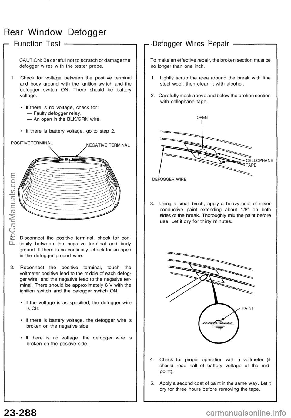
Rear Window Defogger
Function Test
CAUTION: Be careful not to scratch or damage the
defogger wires with the tester probe.
1. Check for voltage between the positive terminal
and body ground with the ignition switch and the
defogger switch ON. There should be battery
voltage.
• If there is no voltage, check for:
— Faulty defogger relay.
— An open in the BLK/GRN wire.
• If there is battery voltage, go to step 2.
POSITIVE TERMINAL
NEGATIVE TERMINAL
2. Disconnect the positive terminal, check for con-
tinuity between the negative terminal and body
ground. If there is no continuity, check for an open
in the defogger ground wire.
3. Reconnect the positive terminal, touch the
voltmeter positive lead to the middle of each defog-
ger wire, and the negative lead to the negative ter-
minal. There should be approximately 6 V with the
ignition switch and the defogger switch ON.
• If the voltage is as specified, the defogger wire
is OK.
• If there is battery voltage, the defogger wire is
broken on the negative side.
• If there is no voltage, the defogger wire is
broken on the positive side.
Defogger Wires Repair
To make an effective repair, the broken section must be
no longer than one inch.
1. Lightly scrub the area around the break with fine
steel wool, then clean it with alcohol.
2. Carefully mask above and below the broken section
with cellophane tape.
OPEN
CELLOPHANE
TAPE
DEFOGGER WIRE
3. Using a small brush, apply a heavy coat of silver
conductive paint extending about 1/8" on both
sides of the break. Thoroughly mix the paint before
use. Let it dry for thirty minutes.
PAINT
4. Check for proper operation with a voltmeter (it
should read half of battery voltage at the mid-
point).
5. Apply a second coat of paint in the same way. Let it
dry for three hours before removing the tape.ProCarManuals.com
Page 1097 of 1640
Idle Control System
Troubleshooting Flowchart
Alternator (ALT) FR Signal
This signals the ECM when the alternator is charging.
Inspection of ALT FR signal.
Connect the test harness be-
tween the ECM and connector.
Disconnect "D" connector from
the engine wire harness only, not
the ECM (see page 11-37).
Turn the ignition switch ON.
Measure voltage between D9 ( + ) terminal and A26 (-) ter-
minal.
Is there approx. 5 V?
Turn the ignition switch OFF.
Reconnect "D" connector to the
engine wire harness.
Warm up engine to normal oper-ating temperature (the cooling
fan comes on).
Measure voltage between D9( + ) terminal and A26 (-) ter-
minal.
Does the voltage decrease when
headlights and rear defogger are
turned on ?
Do the ECM Reset Procedure
(see page 11-35).
ALT FR signal is OK.(To page 11-93) Substitute a known-good ECM
and recheck. If prescribed
voltage is now available, replace
the original ECM.
Turn the ignition switch OFF.ProCarManuals.com
Page 1106 of 1640
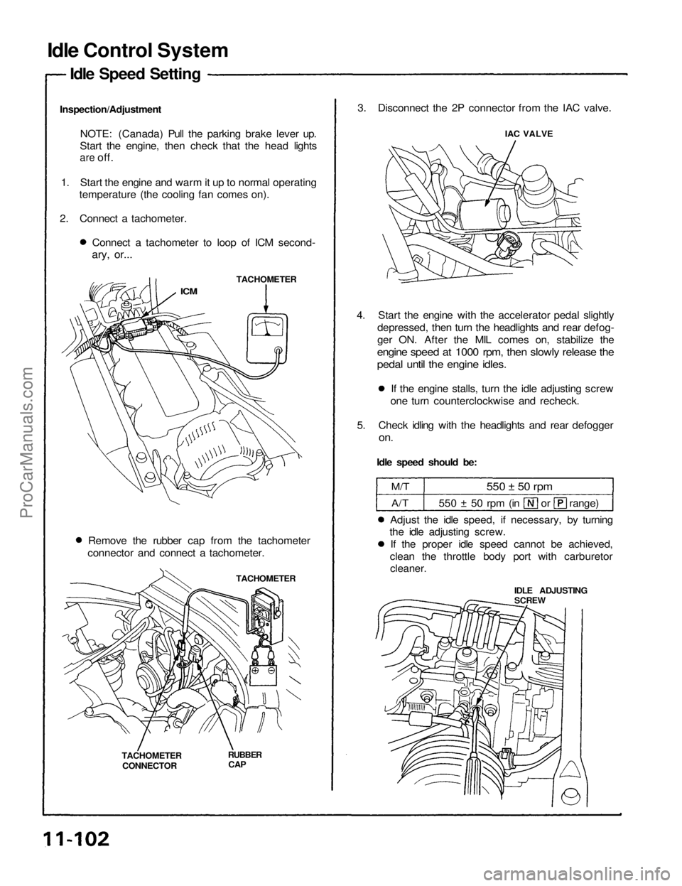
Idle Control System
Idle Speed Setting
Inspection/Adjustment NOTE: (Canada) Pull the parking brake lever up.
Start the engine, then check that the head lights
are
off.
1. Start the engine and warm it up to normal operating temperature (the cooling fan comes on).
2. Connect a tachometer. Connect a tachometer to loop of ICM second-
ary, or...
TACHOMETER
ICM
Remove the rubber cap from the tachometer
connector and connect a tachometer.
TACHOMETER
TACHOMETER CONNECTOR
RUBBER
CAP
3. Disconnect the 2P connector from the IAC valve.
IAC VALVE
4. Start the engine with the accelerator pedal slightly depressed, then turn the headlights and rear defog-
ger ON. After the MIL comes on, stabilize the
engine speed at 1000 rpm, then slowly release the
pedal until the engine idles.
If the engine stalls, turn the idle adjusting screw
one turn counterclockwise and recheck.
5. Check idling with the headlights and rear defogger
on.
Idle speed should be:
M/T
A/T
550 ± 50 rpm
550 ± 50 rpm (in or range)
Adjust the idle speed, if necessary, by turning
the idle adjusting screw.
If the proper idle speed cannot be achieved,
clean the throttle body port with carburetor
cleaner.
IDLE ADJUSTING
SCREWProCarManuals.com