Page 2003 of 2103
SRS General Information
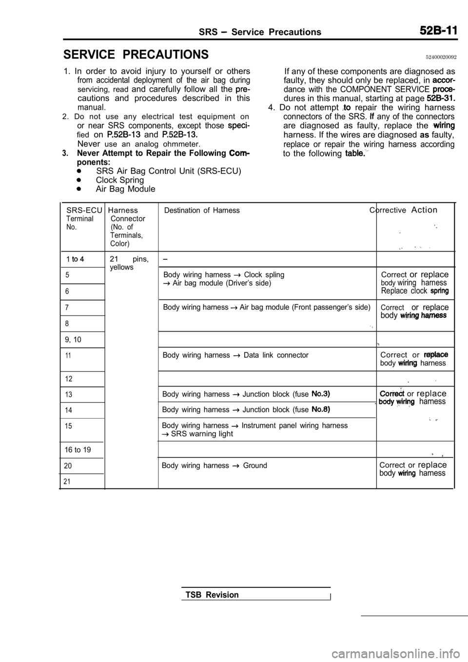
CONFIGURATION DIAGRAMS
D a s h p a n e l
Ignition switch
Air bag module (front passenger’s side)
Data link connector (For scan tool)Data link connector (For scan tool)
Instrument panel
Clock spring
Air bag module (driver’s side)
-18
Combination meter (For warning light)
Combination meter (For SRS warning light)
C-i 8 air bag control unit
TSB Revision
Page 2004 of 2103
SRS General Information.
CIRCUIT DIAGRAM
CAUTION
1.Do not repair, splice or modify SRS wiring (except for specific repairs to the body harness
shown on page
replace wiring if necessary, after reading and fol lowing all precautions
and procedures in this manual.
2.Do not use an analog ohmmeter to check wiring or components; use only special tools
(refer to
and digital multi-meter (refer to
IGNITION
23
I
25
13
CONDITIONING AUTO-CRUISECONTROL SYSTEM CHARGING SYSTEM . COOLING SYSTEM
. IGNIT. METER. MFI
ELC AUTOMATIC TRANSAXLE ION SYSTEMAND GAUGES
14
COMBINATIONMETER
. AUTO-CRUISECONTROL SYSTEM SEAT BELTWARNING BUZZER WINDOWDEFOGGER
C. C.POWER SOURCE CIRCUITCONVERTERWATCH-DOG CIRUIT WARNING LIGHT,
DRIVE CIRCUIT ANALOG SENSOR
I IIIBACK-UP
CAPACITORMICROPROCESSORI
AIR BAG DRIVE CIRCUIT
SAG DRIVE CIRCUIT IIIAA
5 6 8
7
2CLOCKSPRINGI
BR2 21
R e m a r k s
n e .AIR BAG AIR BAG MODULE (DRIVER'S SIDE) (PASSENGER'S SIDE)
TSB Revision
Page 2007 of 2103

SRS Service Precautions
SERVICE PRECAUTIONS52400020092
1. In order to avoid injury to yourself or others
from accidental deployment of the air bag during
servicing, read and carefully follow all the
cautions and procedures described in this
manual.
2. Do not use any electrical test equipment on
or near SRS components, except those
fiedon and
Never use an analog ohmmeter.
3.Never Attempt to Repair the Following
ponents:
SRS Air Bag Control Unit (SRS-ECU)
Clock Spring
Air Bag Module If any of these components are diagnosed as
faulty, they should only be replaced, in
dance with the COMPONENT SERVICE
dures in this manual, starting at page
4. Do not attempt repair the wiring harness
connectors of the SRS. any of the connectors
are diagnosed as faulty, replace the
harness. If the wires are diagnosed asfaulty,
replace or repair the wiring harness according
to the following
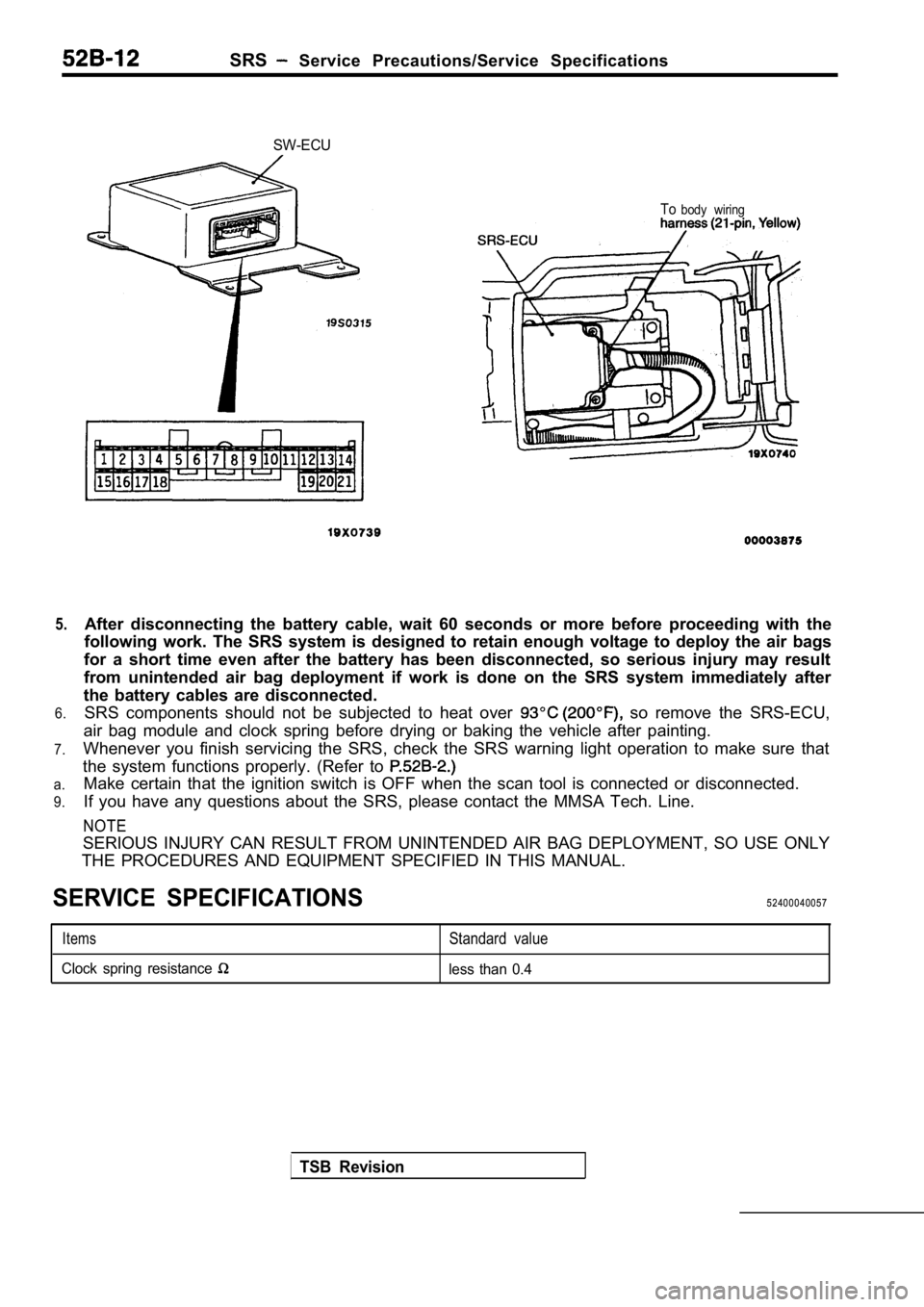
SRS-ECU HarnessDestination of HarnessCorrective A c t i o n
TerminalConnector
No.(No. of
Terminals,
Color)
121 pins,
yellows5Body wiring harness Clock splingCorrector replace
Air bag module (Driver’s side)bodywiring harness
6Replace clock
7Body wiring harness Air bag module (Front passenger’s side)Corrector replace
body
8
9, 10
11Body wiring harness Data link connectorCorrect or
body harness
12
13
14
15
Body wiring harness Junction block (fuse
Body wiring harness Junction block (fuse
Body wiring harness Instrument panel wiring harness
SRS warning light .
or
replace. harness
16 to 19 ,
20
21
Body wiring harness GroundCorrect or replace
body harness
TSB RevisionI
Page 2008 of 2103

SRS Service Precautions/Service Specifications
5.
6.
7.
a.
9.
SW-ECU
Tobody wiring
After disconnecting the battery cable, wait 60 seco nds or more before proceeding with the
following work. The SRS system is designed to retai n enough voltage to deploy the air bags
for a short time even after the battery has been di sconnected, so serious injury may result
from unintended air bag deployment if work is done on the SRS system immediately after
the battery cables are disconnected. SRS components should not be subjected to heat over
so remove the SRS-ECU,
air bag module and clock spring before drying or ba king the vehicle after painting.
Whenever you finish servicing the SRS, check the SR S warning light operation to make sure that
the system functions properly. (Refer to
Make certain that the ignition switch is OFF when t he scan tool is connected or disconnected.
If you have any questions about the SRS, please con tact the MMSA Tech. Line.
NOTE
SERIOUS INJURY CAN RESULT FROM UNINTENDED AIR BAG D EPLOYMENT, SO USE ONLY
THE PROCEDURES AND EQUIPMENT SPECIFIED IN THIS MANU AL.
SERVICE SPECIFICATIONS52400040057
ItemsStandard value
Clock spring resistance less than 0.4
TSB Revision
Page 2011 of 2103

SRS
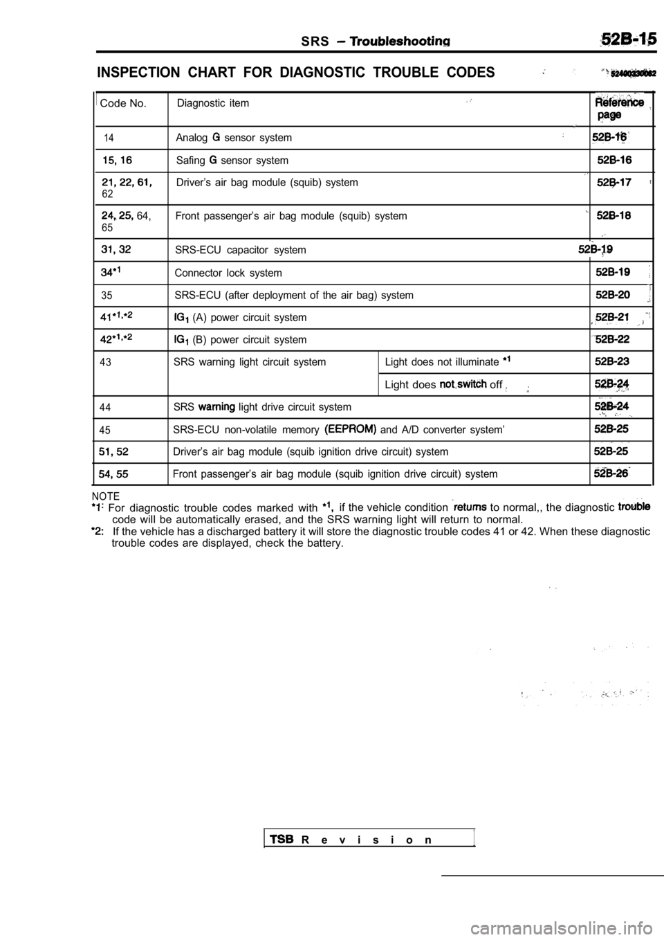
INSPECTION CHART FOR DIAGNOSTIC TROUBLE CODES
Code No.Diagnostic item
14Analog sensor system
Safing sensor system
Driver’s air bag module (squib) system
62
64, Front passenger’s air bag module (squib) system
65
SRS-ECU capacitor system
Connector lock system
35SRS-ECU (after deployment of the air bag) system
(A) power circuit system
(B) power circuit system
43SRS warning light circuit system Light does not illuminate
Light does off
44SRS light drive circuit system
45SRS-ECU non-volatile memory and A/D converter system’
Driver’s air bag module (squib ignition drive circuit) system
Front passenger’s air bag module (squib ignition dr ive circuit) system
NOTE
For diagnostic trouble codes marked with if the vehicle condition to normal,, the diagnostic
code will be automatically erased, and the SRS warn ing light will return to normal.
If the vehicle has a discharged battery it will store the diagnostic trouble codes 41 or 42. When thes e diagnostic
trouble codes are displayed, check the battery.
R e v i s i o n1
Page 2019 of 2103
![MITSUBISHI SPYDER 1990 Service Repair Manual SRS
Code No. 43 warning light drive circuit system
(Light does not illuminate.)
[Comment]This diagnostic trouble code is output when an open circuit occurs for a continuous
period of 5 MITSUBISHI SPYDER 1990 Service Repair Manual SRS
Code No. 43 warning light drive circuit system
(Light does not illuminate.)
[Comment]This diagnostic trouble code is output when an open circuit occurs for a continuous
period of 5](/manual-img/19/57345/w960_57345-2018.png)
SRS
Code No. 43 warning light drive circuit system
(Light does not illuminate.)
[Comment]This diagnostic trouble code is output when an open circuit occurs for a continuous
period of 5 seconds while the SRS-ECU is monitoring the SRS warning light and
the light is OFF (transistor OFF). However, if this code is output due to an open circ uit, if the vehicle condition returns
to
this diagnostic trouble code will be automatically erased, and the SRS light will switch off.
Battery
cable
SRS check harness
OK
Probable cause
of harnesses or connectors
l bulbl Malfunction of l Malfunction of combination meter
Caution
Turn the ignition key to the “LOCK”
the negative battery cable and tape the
Wait at least 60 seconds after disconnecting the ba ttery
cable before doing any further work. (Refer to
Measure at SRS check harness
connector (5). l Disconnect SRS-ECU connector
l Connect SRS check harness
connector (3).
l between terminals (20)
OK: Continuity
OK
[Check trouble symptom.
l Ignition switch: ON
l Connect terminal (15) to the body ground.
OK: Light illuminates
TSB Revision
Page 2020 of 2103
![MITSUBISHI SPYDER 1990 Service Repair Manual SRS Troubleshootina
Code No. 43 warning light drive circuit system
(Light does not switch off.) Probable cause
Insulating tape
[Comment]l
Malfunction of harnesses or connectors
Thi MITSUBISHI SPYDER 1990 Service Repair Manual SRS Troubleshootina
Code No. 43 warning light drive circuit system
(Light does not switch off.) Probable cause
Insulating tape
[Comment]l
Malfunction of harnesses or connectors
Thi](/manual-img/19/57345/w960_57345-2019.png)
SRS Troubleshootina
Code No. 43 warning light drive circuit system
(Light does not switch off.) Probable cause
Insulating tape
[Comment]l
Malfunction of harnesses or connectors
This diagnostic trouble code is output when a to ground occurs in the harness l Malfunction of between the light and the SRS-ECU while the SRS-ECU is monitoring the SRS light and the light is ON.
Caution
Turn the ignition key to the “LOCK” position, disco nnect
the negative battery cable and tape the terminal.
Wait at least 60 seconds, after disconnecting the battery
cable before doing any further work. (Refer to P.
Battery cable
Does light switch off when SRS-ECU connector
Replace the SRS-ECU. Check trouble symptom.N GRepair
Probable cause
Code No. 44 warning light drive circuit system
[Comment]l Malfunction of SRS-ECU
This diagnostic trouble code is output when a short occurs in the light drive circuit
or a malfunction of the output transistor inside th e SRS-ECU is detected while the
SRS-ECU is
the SRS liaht drive circuit.
Insulating tape
Battery cable
Caution
Turn the ignition key to the “LOCK” position, disco nnect
the negative battery cable and tape the
Wait at least 60 seconds after disconnecting the battery
cable before doing any further work. (Refer to P.
Replace the SRS-ECU.
TSB Revision
Page 2022 of 2103
SRS Troubleshooting
Code or 55 Front passenger’s air bag module
(Squib ignition drive
system Probable cause
[Comment]l
Malfunction of SRS-ECUThese diagnostic trouble codes are output when a sh ort-circuit or open circuit occurs in the squib ignition drive circuit inside the SRS-ECU.
Insulating tape
Battery cable
Caution
Turn the ignition key to the “LOCK” position, disco nnect
the negative battery cable and tape the terminal.
Wait at least 60 seconds after disconnecting the battery
cable before doing any further work. (Refer to
Replace the SRS-ECU.
lightwarning
TSB Revision
SRS WARNING LIGHT INSPECTION
1. Check that the warning ‘light
ignition switch is in the ON position.
2.Check that it illuminates for approximately 7 and
then switches off.
3.If the above is not the case, check the diagnostic trouble
codes.