1990 MITSUBISHI SPYDER warning light
[x] Cancel search: warning lightPage 1986 of 2103
INTERIOR Front Seat Belt
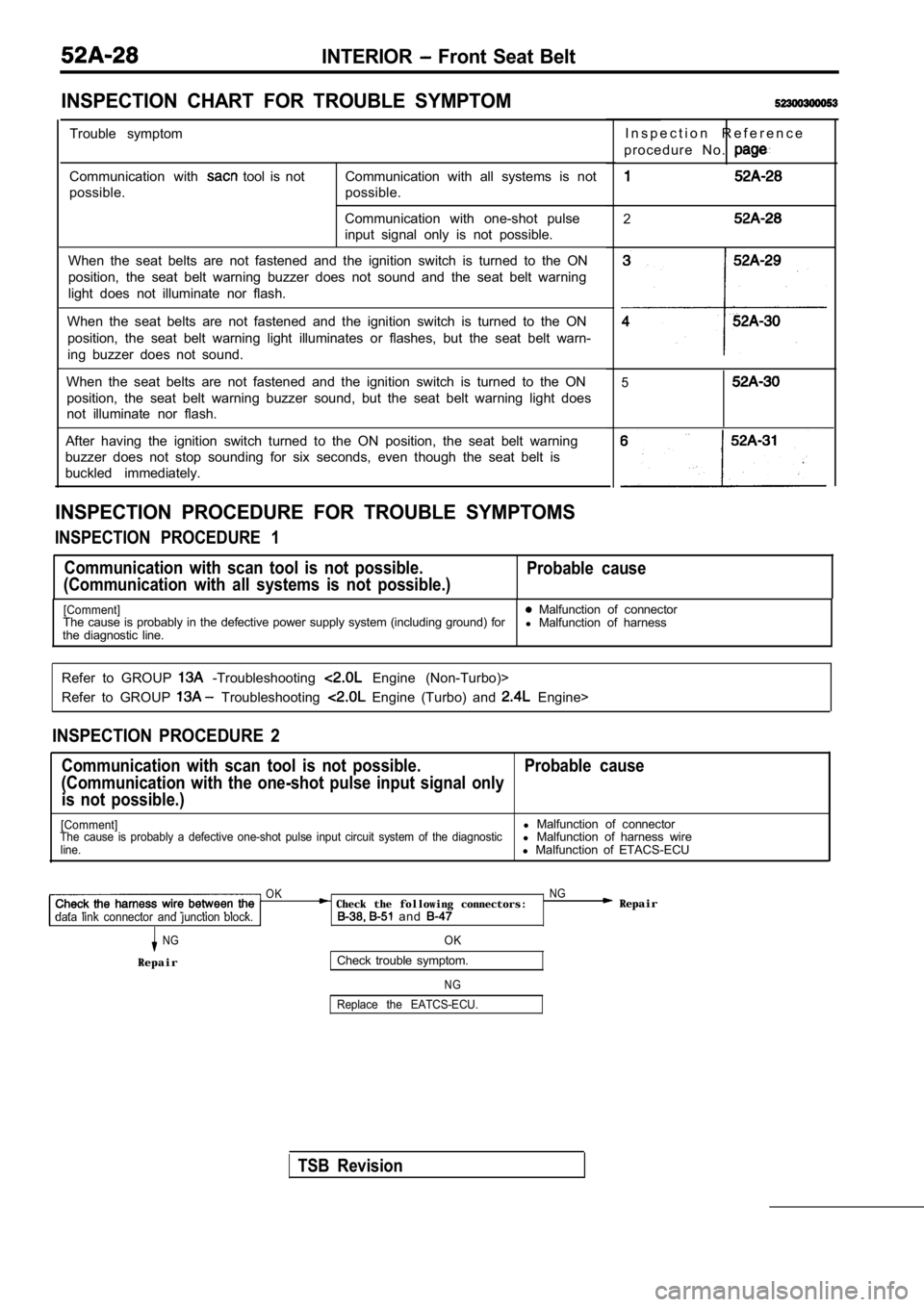
INSPECTION CHART FOR TROUBLE SYMPTOM
Trouble symptom
Communication with
tool is not
possible. Communication with all systems is not
possible.
Communication with one-shot pulse
input signal only is not possible.
When the seat belts are not fastened and the igniti on switch is turned to the ON
position, the seat belt warning buzzer does not sou nd and the seat belt warning
light does not illuminate nor flash.
When the seat belts are not fastened and the igniti on switch is turned to the ON
position, the seat belt warning light illuminates o r flashes, but the seat belt warn-
ing buzzer does not sound.
When the seat belts are not fastened and the igniti on switch is turned to the ON
position, the seat belt warning buzzer sound, but t he seat belt warning light does
not illuminate nor flash.
After having the ignition switch turned to the ON p osition, the seat belt warning
buzzer does not stop sounding for six seconds, even though the seat belt is
buckled immediately.
INSPECTION PROCEDURE FOR TROUBLE SYMPTOMS
INSPECTION PROCEDURE 1
I n s p e c t i o n R e f e r e n c e
p r o c e d u r e N o .
2
3
4
5
Communication with scan tool is not possible.
(Communication with all systems is not possible.) Probable cause
[Comment] Malfunction of connector
The cause is probably in the defective power supply system (including ground) for
l Malfunction of harness
the diagnostic line.
Refer to GROUP
-Troubleshooting Engine (Non-Turbo)>
Refer to GROUP
Troubleshooting Engine (Turbo) and Engine>
INSPECTION PROCEDURE 2
Communication with scan tool is not possible. Probab le cause
(Communication with the one-shot pulse input signal only
is not possible.)
[Comment]l Malfunction of connectorThe cause is probably a defective one-shot pulse in put circuit system of the diagnosticl Malfunction of harness wireline.l Malfunction of ETACS-ECU
OK NG Check the following connectors: Repairdata link connector and junction block. and
NGOK
RepairCheck trouble symptom.
N G
Replace the EATCS-ECU.
TSB Revision
Page 1988 of 2103

INTERIOR Front Seat Belt
INSPECTION PROCEDURE 4,
When the seat belts are not fastened and the ignitionProbable cause
switch is turned to the ON position, the seat belt warning
light illuminates or flashes, but the seat belt war ning
.
er does not sound.
[Comment]lMalfunction of front seat belt buckle It is possible that there is a malfunction of the front seat belt switch circuit.
l Malfunction of l Malfunction of ETACS-ECU
Replace the ETACS-ECU.
NG.
INSPECTION PROCEDURE 5
Front seat belt buckle switch input circuitsysyem check.
(Refer to
When the seat belts are not fastened and the igniti onProbable cause
switch is turned to the ON position, the seat belt warning.,
buzzer sounds, but the seat belt warning light does not il-
luminate nor flash.
[Comment]l Malfunction of bulbIt is possible that there is a malfunction of the s eat belt warning light circuit or l Malfunction of ECU.l Malfunction of harness wire
l Malfunction of ETACS-ECU
OKNG the followina connectors:NG
TSB Revision
junction block and combination meter.
OKOKNGNGDisconnectthejunction blockconnector Check the following connectors:
Disconnectthejunction blockconnector Check the following connectors: and measure at the harness side. and measure at the harness side. and and llContinuity between terminal (5) and
Continuity between terminal (5) and
NGNG Repair Repair
OK: ContinuityNGCheck trouble symptom. Check the harness wire between block and combination
trouble symptom.Replace the ETACS-ECU.
Repair, if necessary.
Page 1990 of 2103
INTERIOR Front Seat Belt
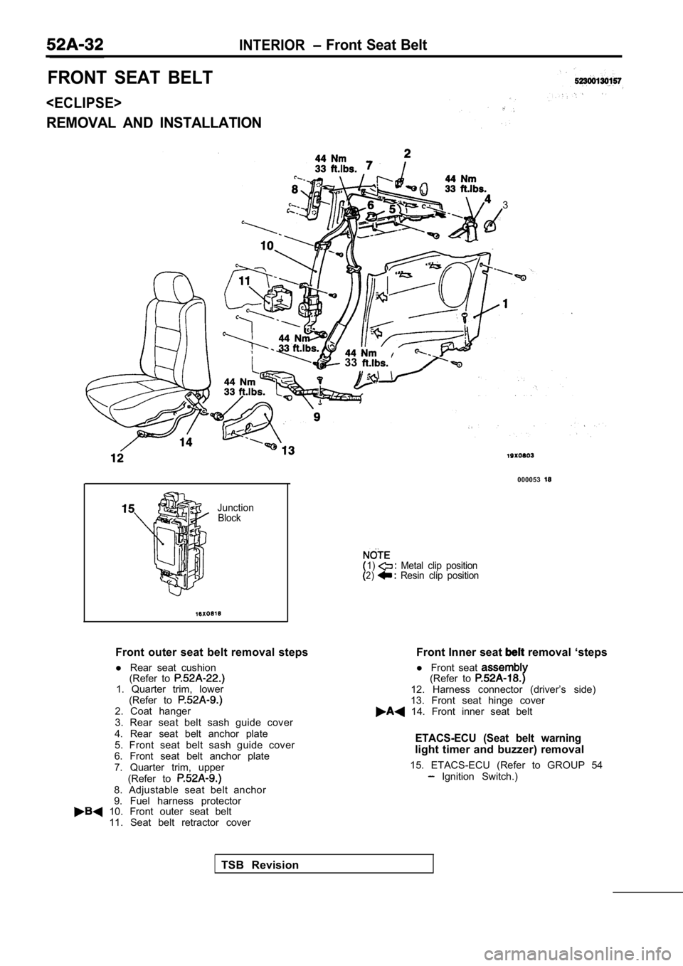
FRONT SEAT BELT
REMOVAL AND INSTALLATION
3
33
000053
JunctionBlock
1) Metal clip position2) Resin clip position
Front outer seat belt removal steps
l Rear seat cushion
(Refer to
1. Quarter trim, lower
(Refer to
2. Coat hanger
3. Rear seat belt sash guide cover
4. Rear seat belt anchor plate
5. Front seat belt sash guide cover
6. Front seat belt anchor plate
7. Quarter trim, upper
(Refer to
8. Adjustable seat belt anchor
9. Fuel harness protector Front Inner seat
removal ‘steps
l Front seat
(Refer to 12. Harness connector (driver’s side)
13. Front seat hinge cover
14. Front inner seat belt
ETACS-ECU (Seat belt warninglight timer and buzzer) removal
15. ETACS-ECU (Refer to GROUP 54
Ignition Switch.)
10. Front outer seat belt 11. Seat belt retractor cover
TSB Revision
Page 1991 of 2103
INTERIOR Front Seat Belt
44 Nm 33
33
JunctionBlock
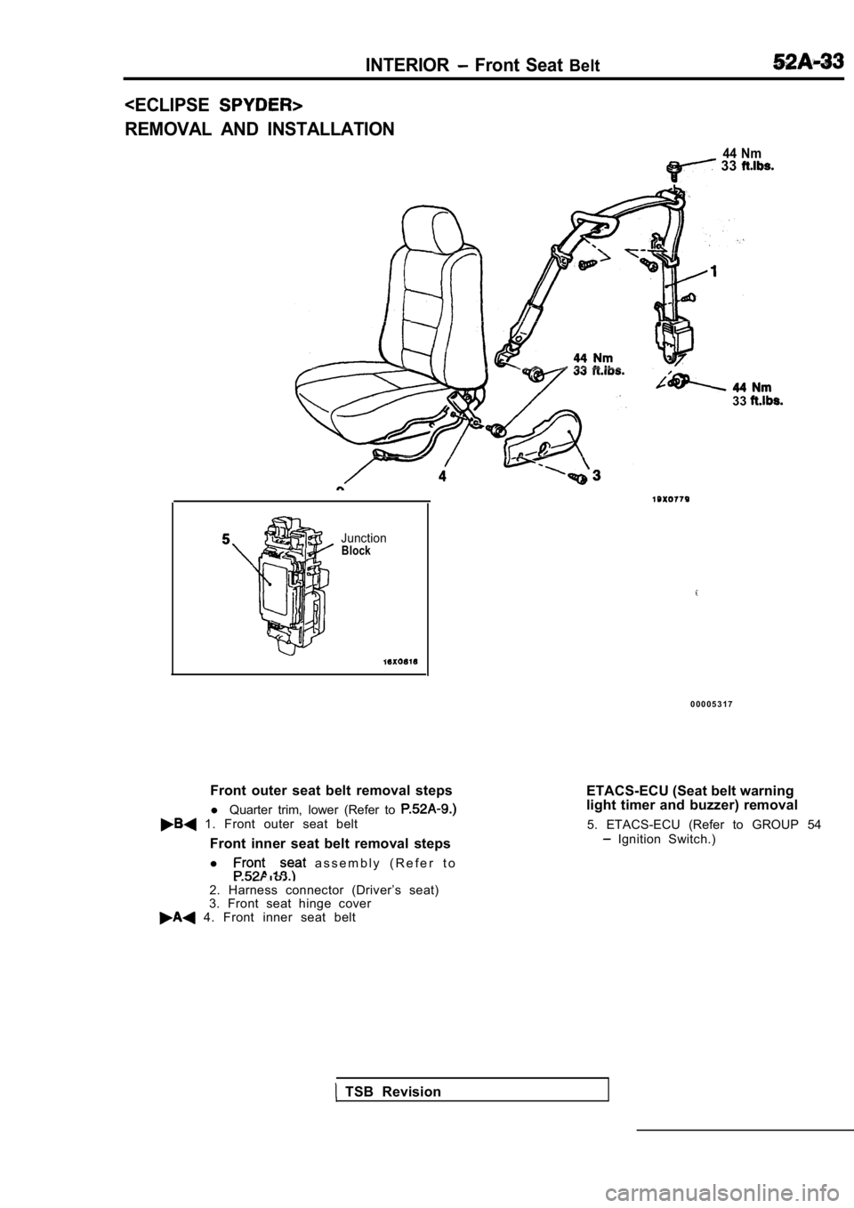
Front outer seat belt removal stepsl Quarter trim, lower (Refer to
1. Front outer seat belt
Front inner seat belt removal steps
l
a s s e m b l y ( R e f e r t o
.
2. Harness connector (Driver’s seat)
3. Front seat hinge cover
4. Front inner seat belt
0 0 0 0 5 3 1 7
ETACS-ECU (Seat belt warning
light timer and buzzer) removal 5. ETACS-ECU (Refer to GROUP 54
Ignition Switch.)
TSB Revision
Page 1998 of 2103
SRS General Information
GENERAL INFORMATION
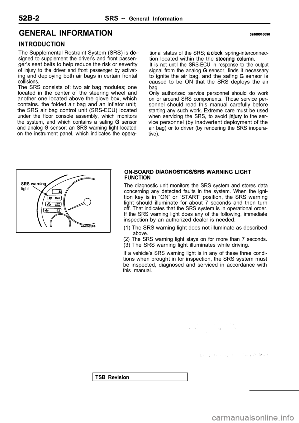
INTRODUCTION
The Supplemental Restraint System (SRS) is
signed to supplement the driver’s and front passen-
ger’s seat belts to help reduce the risk or severity
of injury to the driver and front passenger by acti vat-
ing and deploying both air bags in certain frontal
collisions.
The SRS consists of: two air bag modules; one
located in the center of the steering wheel and
another one located above the glove box, which
contains. the folded air bag and an inflator unit;
the SRS air bag control unit (SRS-ECU) located
under the floor console assembly, which monitors
the system, and which contains a safing
sensor
and analog
sensor; an SRS warning light located
on the instrument panel, which indicates the
tional status of the SRS; spring-interconnec-
tion located within the the
It is not until the SRS-ECU in response to the outp ut
signal from the analog sensor, finds it necessary
to ignite the air bag, and the safing sensor is
caused to be ON that the SRS deploys the air
bag.
Only authorized service personnel should do work
on or around SRS components. Those service per-
sonnel should read this manual carefully before
starting any such work. Extreme care must be used
when servicing the SRS, to avoid
to the ser-
vice personnel (by inadvertent deployment of the
air bag) or to driver (by rendering the SRS inopera -
tive).
SRSlight
ON-BOARD WARNING LIGHT
FUNCTION
The diagnostic unit monitors the SRS system and sto res data
concerning any detected faults in the system. When the igni-
tion key is in “ON” or “START’ position, the SRS wa rning
light should illuminate for about 7 seconds and the n turn
off. That indicates that the SRS system is in operational order.
If the SRS warning light does any of the following, immediate
inspection by an authorized dealer is needed.
(1) The SRS warning light does not illuminate as de scribed
above.
(2) The SRS warning light stays on for more than 7 seconds.
(3) The SRS warning light illuminates while driving.
If a vehicle’s SRS warning light is in any of these three condi-
tions when brought in for inspection, the SRS syste m must
be inspected, diagnosed and serviced in accordance with
this manual.
TSB Revision
Page 1999 of 2103
SRS General
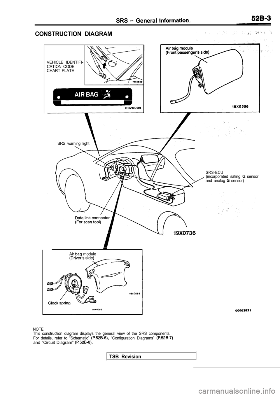
CONSTRUCTION DIAGRAM
VEHICLE IDENTIFI-CATION CODE
CHART PLATE
Air
module
SRS warning light
SRS-ECU(incorporated safing sensor
and analog sensor)
NOTEThis construction diagram displays the general view of the SRS components.
For details, refer to “Schematic” “Configuration Diagrams” and “Circuit Diagram”
TSB Revision
Page 2001 of 2103
SRS General- Jnformation
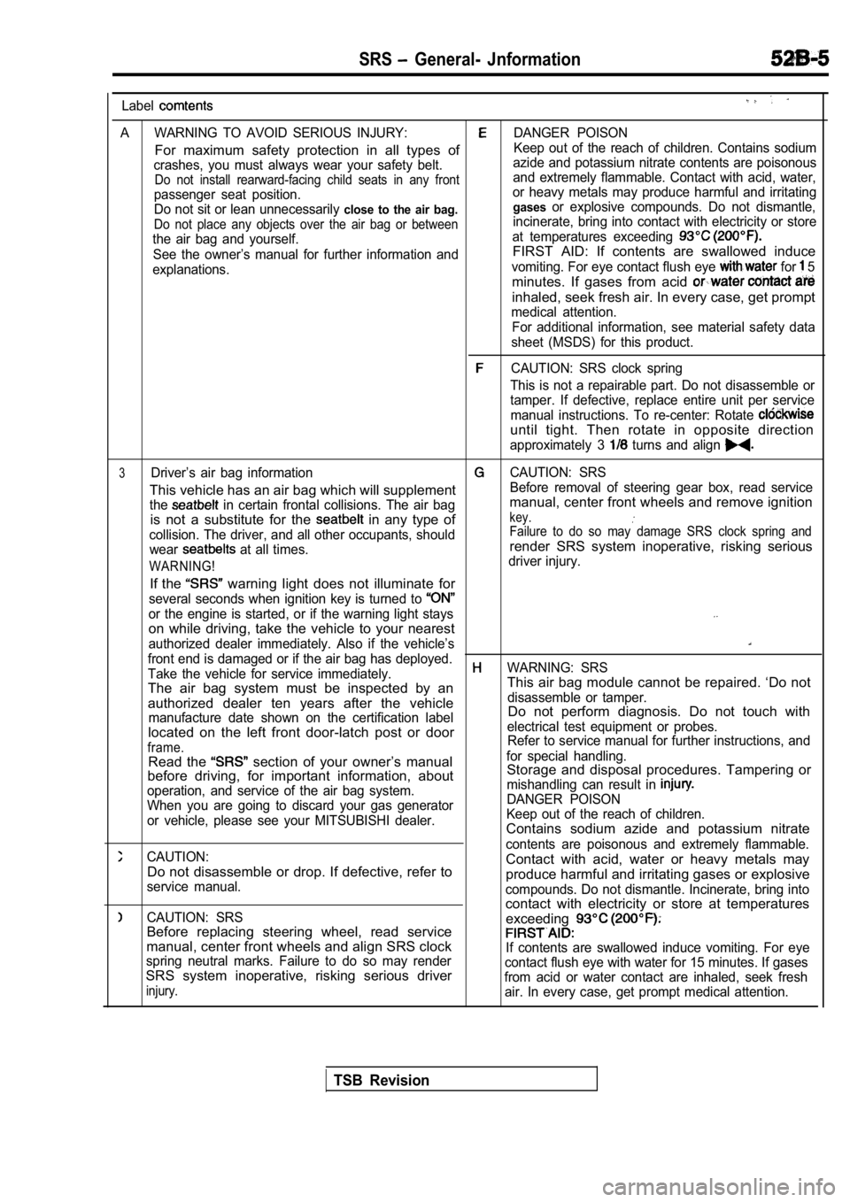
Label
A WARNING TO AVOID SERIOUS INJURY:DANGER POISON
For maximum safety protection in all types ofKeep out of the reach of children. Contains sodium
crashes, you must always wear your safety belt. azide and potassium nitrate contents are poisonous
Do not install rearward-facing child seats in any f
rontand extremely flammable. Contact with acid, water,
passenger seat position. or heavy metals may produce harmful and irritating
Do not sit or lean unnecessarily
close to the air bag. gasesor explosive compounds. Do not dismantle,
Do not place any objects over the air bag or betwee
nincinerate, bring into contact with electricity or store
the air bag and yourself. at temperatures exceeding
See the owner’s manual for further information andFIRST AID: If contents are swallowed induce
explanations.vomiting. For eye contact flush eye for 5
minutes. If gases from acid
inhaled, seek fresh air. In every case, get prompt
medical attention.
For additional information, see material safety dat a
sheet (MSDS) for this product.
CAUTION: SRS clock spring
This is not a repairable part. Do not disassemble o r
tamper. If defective, replace entire unit per servi ce
manual instructions. To re-center: Rotate
until tight. Then rotate in opposite direction
approximately 3 turns and align
3Driver’s air bag informationCAUTION: SRS
This vehicle has an air bag which will supplementBefore removal of steering gear box, read service
the
in certain frontal collisions. The air bagmanual, center front wheels and remove ignition
is not a substitute for the
in any type ofkey.
collision. The driver, and all other occupants, sho uldFailure to do so may damage SRS clock spring and
wear at all times.render SRS system inoperative, risking serious
WARNING!driver injury.
If the warning light does not illuminate for
several seconds when ignition key is turned to
or the engine is started, or if the warning light stays
on while driving, take the vehicle to your nearest
authorized dealer immediately. Also if the vehicle’ s
front end is damaged or if the air bag has deployed .
Take the vehicle for service immediately.WARNING: SRS
The air bag system must be inspected by an This air bag module cannot be repaired. ‘Do not
authorized dealer ten years after the vehicledisassemble or tamper.
manufacture date shown on the certification labelDo not perform diagnosis. Do not touch with
located on the left front door-latch post or door
electrical test equipment or probes.
frame.Refer to service manual for further instructions, a nd
Read the section of your owner’s manualfor special handling.
before driving, for important information, about Storage and disposal procedures. Tampering or
operation, and service of the air bag system. mishandling can result in
When you are going to discard your gas generatorDANGER POISON
or vehicle, please see your MITSUBISHI dealer. Keep out of the reach of children.
Contains sodium azide and potassium nitrate
CAUTION:contents are poisonous and extremely flammable.
Do not disassemble or drop. If defective, refer toContact with acid, water or heavy metals may
service manual.produce harmful and irritating gases or explosive
compounds. Do not dismantle. Incinerate, bring into
CAUTION: SRScontact with electricity or store at temperatures
exceeding
Before replacing steering wheel, read service
manual, center front wheels and align SRS clockIf contents are swallowed induce vomiting. For eye
spring neutral marks. Failure to do so may render contact flush eye with water for 15 minutes. If gases
SRS system inoperative, risking serious driverfrom acid or water contact are inhaled, seek freshinjury.air. In every case, get prompt medical attention.
TSB Revision
Page 2002 of 2103
SRS General Information
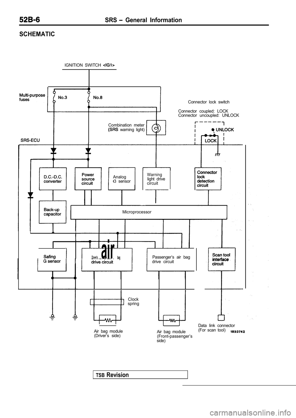
SCHEMATIC
IGNITION SWITCH
Combination meter warning light) Connector lock switch
Connector coupled: LOCK
Connector uncoupled: UNLOCK
II
AnalogWarning
3 sensor light drive
circuit
Microprocessor
TSBRevision
Clock
spring
I air Passenger’s air bag
drive circuit
I
Air bag module (Driver’s side) Scan tool
interface
circuit
Data link connector
Air bag module (For scan tool)
(Front-passenger’s
side)