1990 MITSUBISHI SPYDER warning light
[x] Cancel search: warning lightPage 1148 of 2103
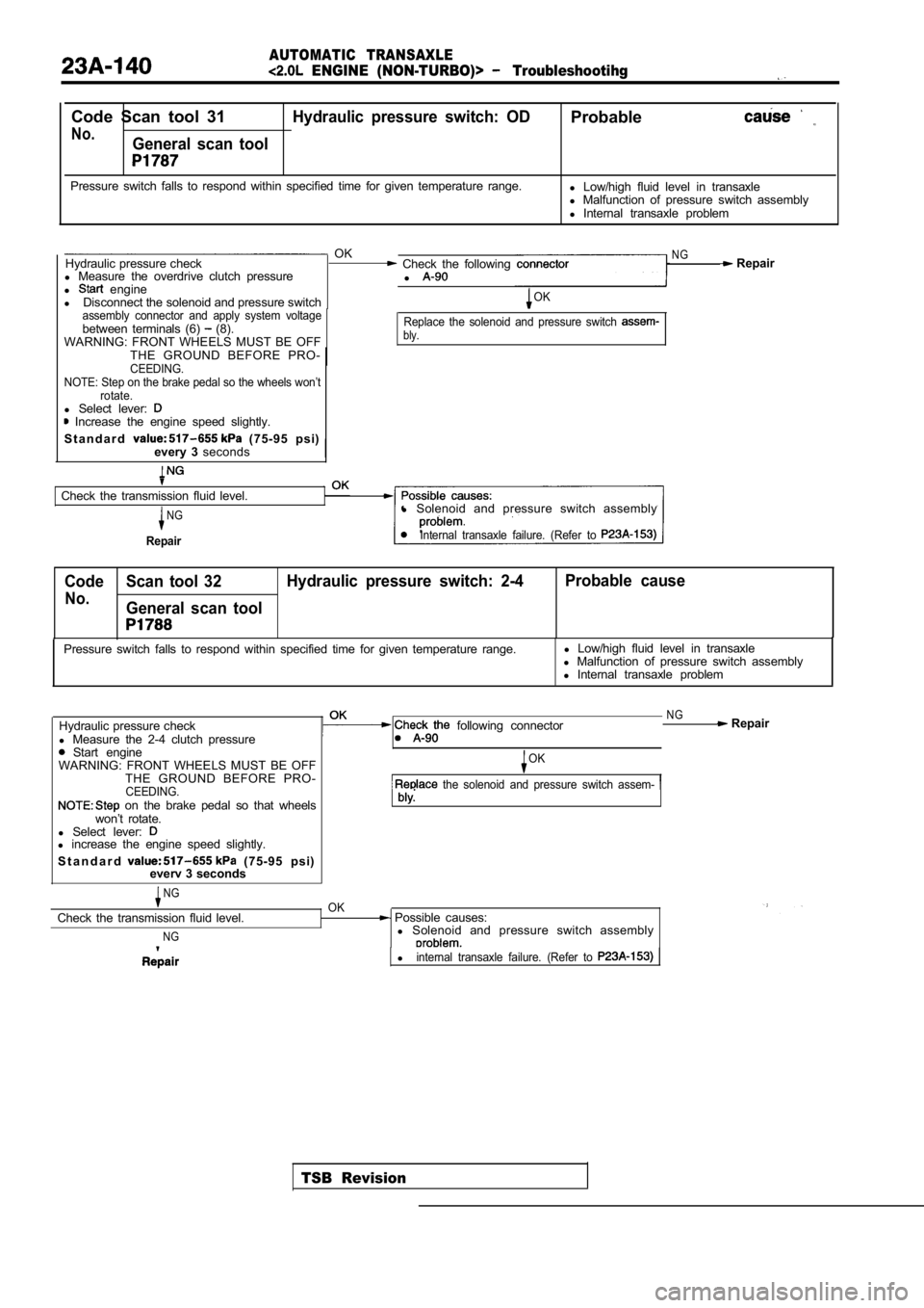
AUTOMATIC TRANSAXLE
ENGINE (NON-TURBO)> Troubleshootihg
Code Scan tool 31Hydraulic pressure switch: ODProbable
No.General scan tool
Pressure switch falls to respond within specified time for given temperature range.
l Low/high fluid level in transaxle
l Malfunction of pressure switch assembly
l Internal transaxle problem
OKNGHydraulic pressure check Check the following Repair
l Measure the overdrive clutch pressure
l
l engine
l Disconnect the solenoid and pressure switchOK
assembly connector and apply system voltage
between terminals (6) (8).
WARNING: FRONT WHEELS MUST BE OFFReplace the solenoid and pressure switch bly.
THE GROUND BEFORE PRO-CEEDING.
NOTE: Step on the brake pedal so the wheels won’t rotate.
l Select lever: Increase the engine speed slightly.
S t a n d a r d
(75-95 psi)
every 3 seconds
Check the transmission fluid level.
NG
Repair
l Solenoid and pressure switch assembly
Internal transaxle failure. (Refer to
Code Scan tool 32 Hydraulic pressure switch: 2-4 Probable cause
No.General scan tool
TSB Revision
Pressure switch falls to respond within specified t
ime for given temperature range.l
Low/high fluid level in transaxle
l Malfunction of pressure switch assembly
l Internal transaxle problem
Hydraulic pressure check
l Measure the 2-4 clutch pressure
Start engine
following connector
WARNING: FRONT WHEELS MUST BE OFF THE GROUND BEFORE PRO-
CEEDING. on the brake pedal so that wheels
won’t rotate.
l Select lever:
l increase the engine speed slightly.
S t a n d a r d
(75-95 psi)
everv 3 seconds
NGOK
NG Repair
OK
the solenoid and pressure switch assem-
Check the transmission fluid level.
NG
Possible causes:
l Solenoid and pressure switch assembly
linternal transaxle failure. (Refer to
Page 1174 of 2103
AUTOMATIC TRANSAXLE
ENGINE (NON-TURBO)> On-vehicle Service
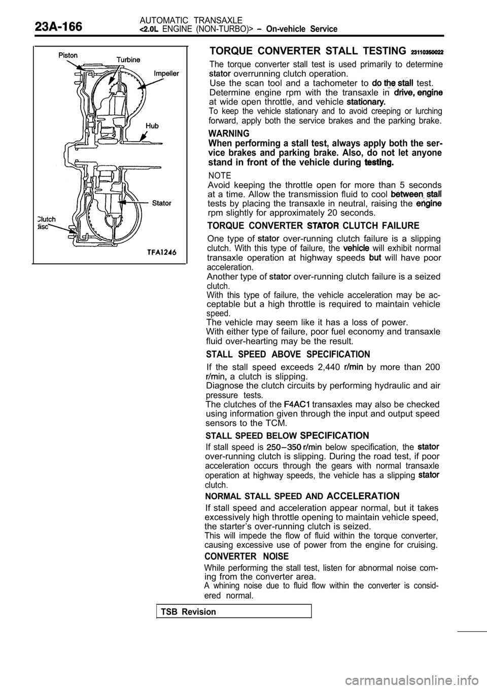
TORQUE CONVERTER STALL TESTING
The torque converter stall test is used primarily to determine
overrunning clutch operation.
Use the scan tool and a tachometer to
test.
Determine engine rpm with the transaxle in
at wide open throttle, and vehicle
To keep the vehicle stationary and to avoid creepin g or lurching
forward, apply both the service brakes and the parking brake.
WARNING
When performing a stall test, always apply both the ser-
vice brakes and parking brake. Also, do not let any one
stand in front of the vehicle during
NOTE
Avoid keeping the throttle open for more than 5 seconds
at a time. Allow the transmission fluid to cool
tests by placing the transaxle in neutral, raising the
rpm slightly for approximately 20 seconds.
TORQUE CONVERTER CLUTCH FAILURE
One type of over-running clutch failure is a slipping
clutch. With this type of failure, the will exhibit normal
transaxle operation at highway speeds will have poor
acceleration.
Another type of over-running clutch failure is a seized
clutch.
With this type of failure, the vehicle acceleration may be ac-
ceptable but a high throttle is required to maintai n vehicle
speed.
The vehicle may seem like it has a loss of power.
With either type of failure, poor fuel economy and transaxle
fluid over-hearting may be the result.
STALL SPEED ABOVE SPECIFICATION
If the stall speed exceeds 2,440 by more than 200
a clutch is slipping.
Diagnose the clutch circuits by performing hydrauli c and air
pressure tests.
The clutches of the transaxles may also be checked
using information given through the input and outpu t speed
sensors to the TCM.
STALL SPEED BELOW SPECIFICATION
If stall speed is below specification, the
over-running clutch is slipping. During the road te st, if poor
acceleration occurs through the gears with normal t ransaxle
operation at highway speeds, the vehicle has a slip ping
clutch.
NORMAL STALL SPEED AND ACCELERATION
If stall speed and acceleration appear normal, but it takes
excessively high throttle opening to maintain vehic le speed,
the starter’s over-running clutch is seized.
This will impede the flow of fluid within the torqu e converter,
causing excessive use of power from the engine for cruising.
CONVERTER NOISE
While performing the stall test, listen for abnormal noise com-
ing from the converter area.
A whining noise due to fluid flow within the conver ter is consid-
ered normal.
TSB Revision
Page 1690 of 2103
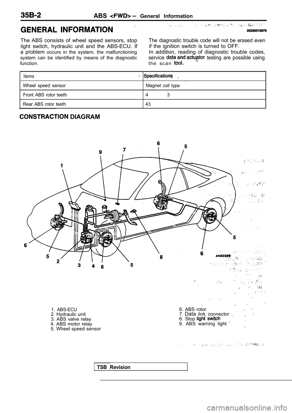
ABS General Information
The ABS consists of wheel speed sensors, stop light switch, hydraulic unit and the ABS-ECU. If
a problem occurs in the system, the malfunctioning
system can be identified by means of the diagnostic
function.
The diagnostic trouble code will not be erased even
if the ignition switch is turned to OFF.
In addition, reading of diagnostic trouble codes,
service testing are possible using
t h e s c a n
Items
Wheel speed sensor
Front ABS rotor teeth
Rear ABS rotor teeth
,
Magnet coil type
4 3
43
DIAGRAM
1. ABS-ECU6. ABS rotor7. Data link connector .
6. Stop
9. ABS warning light
2. Hydraulic unit
3. ABS valve relay
4. ABS motor relay
5. Wheel speed sensor
TSB Revision
Page 1693 of 2103
warning light
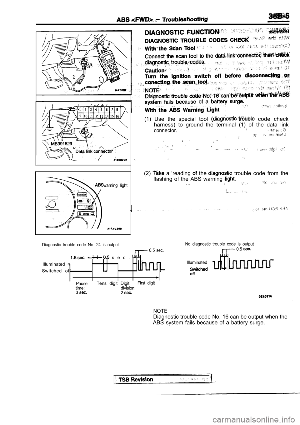
(1) Use the special tool code check
harness) to ground the terminal (1) of the data lin k
connector.
,
.
(2) a ‘reading the trouble code from the
flashing of the ABS warning
.
Diagnostic trouble code No. 24 is output
0.5 sec. No diagnostic trouble code is output 0.5
s e c .
IlluminatedIlluminated
Switched off
.
PauseTens digit DigitFirst digit
time: division: 3
2
NOTE
Diagnostic trouble code No. 16 can be output when t he
ABS system fails because of a battery surge.
Page 1694 of 2103
ABS
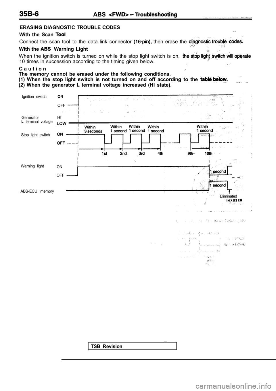
ERASING DIAGNOSTIC TROUBLE CODES
With the Scan . .
Connect the scan tool to the data link connector then erase the
With the Warning Light
When the ignition switch is turned on while the sto p light switch is on,
10 times in succession according to the timing given below.
C a u t i o n
The memory cannot be erased under the following con ditions.
(1) When the stop light switch is not turned on and off according to the
(2) When the generator terminal voltage increased (HI state).
Ignition switch
Generator
terminal voltage
Stop light switch
Warning light
ON
OFF
II
ON
OFF_ _
ABS-ECU memory . . .Eliminated
TSB Revision
Page 1703 of 2103

ABS Troubleshooting
ABS WARNING LIGHT CHECK’
.
Check that the ABS warning light as-
1. When the ignition switch is turned
warning light illuminates..
2. When the ignition switch is turned to “START”, t
o
the engine, the ABS warning light
1 second.
3. If the is other’ above, check
diagnostic trouble codes.
Revision
Page 1704 of 2103
6ABS
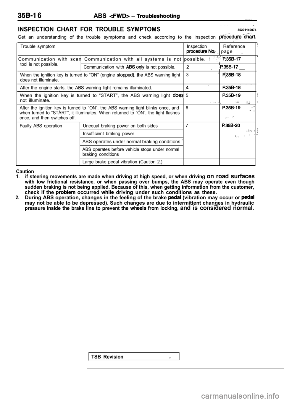
INSPECTION CHART FOR TROUBLE SYMPTOMS35201140074
Get an understanding of the trouble symptoms and check according to the inspection
Trouble symptom InspectionReference
p a g e
C o m m u n i c a t i o n w i t h s c a n C o m m u n i c a t i o n w i t h a l l s y s te m s i s n o t p o s s i b l e . 1
tool is not possible.
Communication with is not possible.2 __
When the ignition key is turned to “ON” (engine ABS warning light3
does not illuminate.
After the engine starts, the ABS warning light rema ins illuminated.
When the ignition key is turned to “START”, the ABS warning light 5
not illuminate.
After the ignition key is turned to “ON”, the ABS warning light blinks once, and6
when turned to “START”, it illuminates. When return ed to “ON”, the light flashes
once, and then switches off.
Faulty ABS operation Unequal braking power on both s ides7
Insufficient braking power
ABS operates under normal braking conditions
ABS operates before vehicle stops under normal
braking conditions
Large brake pedal vibration (Caution 2.)
Caution
1.if steering movements are made when driving at high speed, or when driving on road surfaces
with low frictional resistance, or when passing over bumps, the ABS may operate even though
sudden braking is not being applied. Because of thi s, when getting information from the customer,
check if the occurred driving under such conditions as these.
2.During ABS operation, changes in the feeling of the brake (vibration may occur or
may not be able to be depressed). Such changes are due to intermittent changes in hydraulic
pressure inside the brake line to prevent the from locking, and is considered normal.
TSB Revision,
Page 1706 of 2103
![MITSUBISHI SPYDER 1990 Service Repair Manual ABS Troubleshooting , ,
INSPECTION PROCEDURE 3When ignition key is turned to “ON” (engine stopped ),
ABS warning light does not illuminate
[Comment]When power is supplied to the MITSUBISHI SPYDER 1990 Service Repair Manual ABS Troubleshooting , ,
INSPECTION PROCEDURE 3When ignition key is turned to “ON” (engine stopped ),
ABS warning light does not illuminate
[Comment]When power is supplied to the](/manual-img/19/57345/w960_57345-1705.png)
ABS Troubleshooting , ,
INSPECTION PROCEDURE 3When ignition key is turned to “ON” (engine stopped ),
ABS warning light does not illuminate
[Comment]When power is supplied to the ABS-ECU, the valve relay changes from to ON by the initial check, and thus even if there is a problem with the circuit between
ABS light and ABS-ECU, the light will illuminate once when the valve relay
is OFF.
Accordingly, the cause of the light not illuminatin g is probably an open circuit in the
light power circuit, a blown light bulb, or an open circuit in both the circuit between
the ABS
light and the ABS-ECU and the circuit between the ABS light and the ABS valve relay.When other lights also do not illuminate, the cause is probably a blown fuse.
Measure at combination meter connector
l Disconnect the connector and mea-
sure at the harness side.
l Ignition Switch ON
lVoltage between terminal 10 and body
OK Battery positive voltage Check trouble symptoms
Measure at combination meter connector
sure at the combination meter side.
l Continuitv between terminals
R e p l a c e t h e
OK Continuity ,
OK
Check the harnesses between the ABS valve relay and the combination meter,
a n d b e t w e e n t h e A B S - E C U a n d
combination meter (common section).
if necessary.
INSPECTION PROCEDURE 4
TSB Revision.
Even after the engine is started, the ABS Warning l ight ,remains illuminated.. .
[Comment]There is probably a short in the ABS warning light illumination circuit.l Malfunction of combination meterl Malfunction of ABS valve relayl Malfunction of ABS-ECU. ,
NOTE
This trouble symptom is limited to cases where comm unication with the scan tool is’
is normal) and the diagnostic trouble code is a normal diagnostic trouble code..YESDisconnect the ABS-ECU connector Does the light remain illuminated?
NO
Short circuit inside the combination or in the harnessbetween the meter and
Replace the ABS-ECU.