Page 90 of 2103
11ENGINE Crankshaft pear Oil
,
BOLT PLATE BOLT
R E M O V A L
Use the special tool to secure. the
or drive plate,
and remove the bolt.
INSTALLATION SERVICE
CRANKSHAFT REAR OIL SEAL INSTALLATION
(1) Apply a small amount of engine oil to the entir e inside
diameter of the oil seal lip.
(2) Tap in the oil seal as shown in the illustratio n.
PLATE BOLT BOLT
(1) Clean off all sealant, oil and other substances which are
adhering to the threaded bolts, crankshaft thread h oles
and the flywheel
or drive plate
(2) Apply oil to the bearing surface of the flywhee l
or drive plate bolt.
(3) Apply oil to the crankshaft thread holes.
(4) Apply sealant to the threaded mounting bolts.
Specified sealant:
Stud locking 4170 or equivalent
TSB Revision
(5) Use the special tool to secure the flywheel or
drive plate and then tighten the the speci-
fied torque.
Specified torque:
Nm
Page 91 of 2103
ENGINE Cylinder Head
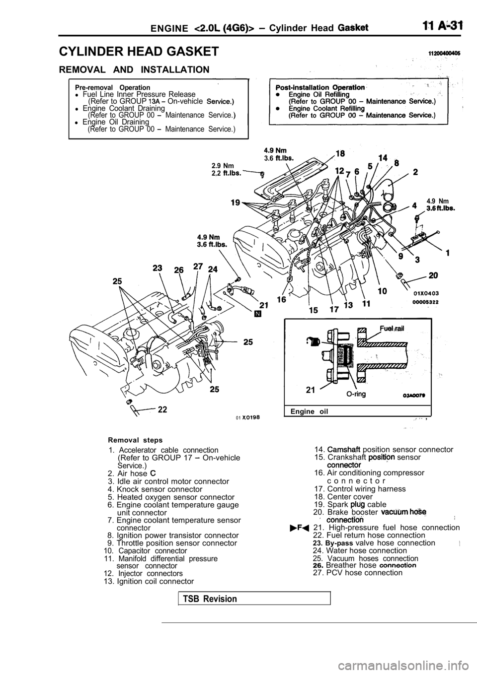
CYLINDER HEAD GASKET
REMOVAL AND INSTALLATION
Pre-removal Operationl Fuel Line Inner Pressure Release(Refer to GROUP On-vehiclel Engine Coolant Draining(Refer to GROUP 00 Maintenance Service.)l Engine Oil Draining(Refer to GROUP 00 Maintenance Service.)
3.62.9 Nm
2.2
4.9 Nm
220 1
Removal steps
1. Accelerator cable connection(Refer to GROUP 17 On-vehicleService.)2. Air hose 3. Idle air control motor connector
4. Knock sensor connector
5. Heated oxygen sensor connector
6. Engine coolant temperature gauge
unit connector
7. Engine coolant temperature sensor
connector8. Ignition power transistor connector
9. Throttle position sensor connector
10. Capacitor connector
11. Manifold differential pressure sensor connector
12. Injector connectors
13. Ignition coil connector Engine oil
,
21
14. position sensor connector
15. Crankshaft sensor
16. Air conditioning compressor
c o n n e c t o r
17. Control wiring harness
18. Center cover
19. Spark
cable
20. Brake booster
21. High-pressure fuel hose connection 22. Fuel return hose connection
23. By-pass valve hose connection
24. Water hose connection25. Vacuum hoses connection26.Breather hose 27. PCV hose connection
TSB Revision
Page 93 of 2103
ENGINE Cylinder Head Gasket,
Intake sideFront of
engine
Exhaust side
REMOVAL SERVICE POINTS
UPPER HOSE/RADIATOR
HOSE
.Place mating marks on the radiator hose and the hos e clamp,
and then disconnect the radiator hose.
HEAD BOLT REMOVAL
Using the special tool, loosen the bolts in the ord er shown
in the illustration (in 2 or 3 stages), and then the
cylinder head assembly.
INSTALLATION SERVICE
CYLINDER HEAD GASKET INSTALLATION
(1) all oil and grease from the gasket mounting
(2) Install the gasket to the cylinder block with the identification
mark facing upwards.
HEAD BOLT INSTALLATION
(1) When installing the cylinder head-bolts, the le ngth below
the head of the bolts should be within the
If it is outside the limit, bolts.
(A): 99.4 mm (3.91 In.)
(2) Apply engine oil to the bolt thread and the was her..
TSB Revision
Page 97 of 2103
ENGINE Timing
(22-44
A
tensioner
marks Cylinder headI surface
I I I
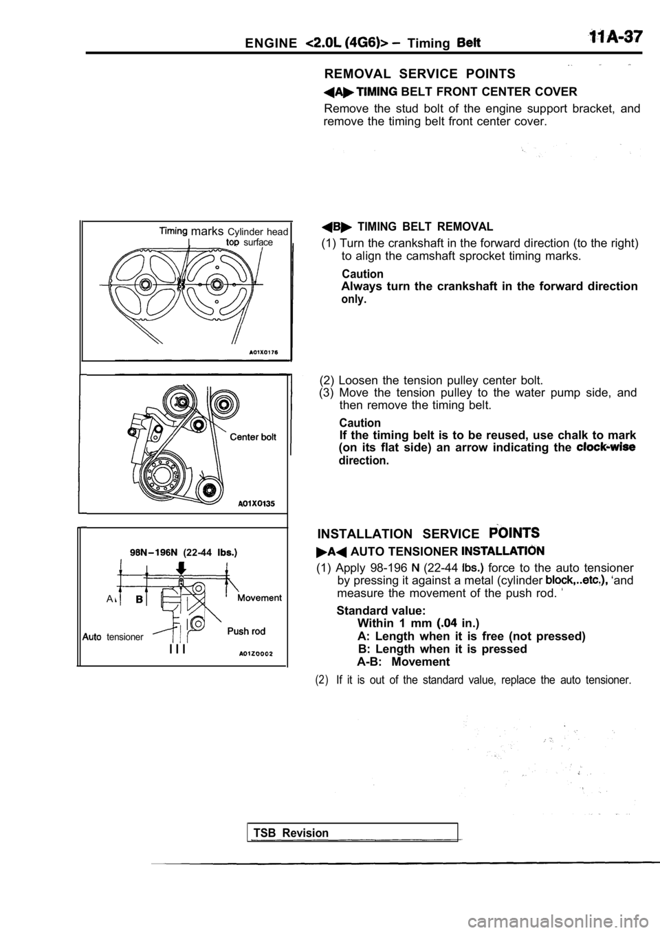
REMOVAL SERVICE POINTS
BELT FRONT CENTER COVER
Remove the stud bolt of the engine support bracket, and
remove the timing belt front center cover.
TIMING BELT REMOVAL
(1) Turn the crankshaft in the forward direction (t o the right)
to align the camshaft sprocket timing marks.
Caution
Always turn the crankshaft in the forward direction
only.
(2) Loosen the tension pulley center bolt.
(3) Move the tension pulley to the water pump side, and
then remove the timing belt.
Caution
If the timing belt is to be reused, use chalk to ma rk
(on its flat side) an arrow indicating the
direction.
INSTALLATION SERVICE
AUTO TENSIONER
(1) Apply 98-196 (22-44 force to the auto tensioner
by pressing it against a metal (cylinder
‘and
measure the movement of the push rod.
Standard value: Within 1 mm
in.)
A: Length when it is free (not pressed) B: Length when it is pressed
A-B: Movement
(2)If it is out of the standard value, replace the aut o tensioner.
TSB Revision
Page 101 of 2103
ENGINE Timing
TIMING BELT
REMOVAL AND INSTALLATION
(Engine oil) Nm
Removal steps1. Timing belt (Refer to
2. Crankshaft sprocket 3. Crankshaft sensing blade l Timing belt tension adjustment
4. Timing belt tensioner 5. Timing belt
__
REMOVAL SERVICE POINTS
CRANKSHAFT SPROCKET
(1) Use thespecial tool to remove the bolt,
(2) Use the special tool to remove the crankshaft
TSB Revision
Page 102 of 2103
ENGINE Timing Belt
CounterbalanceBelt tension side
Timingmarks
Belt tension side tension side
installation bolt
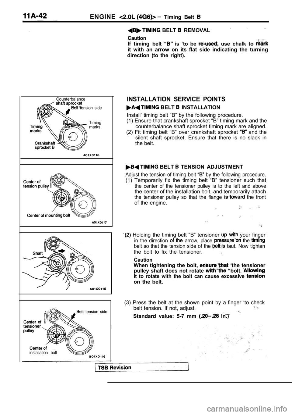
BELT REMOVAL
Caution
If timing belt is ‘to be use chalk to
it with an arrow on its flat side indicating the tu rning
direction (to the right).
INSTALLATION SERVICE POINTS
BELT INSTALLATION
Install’ timing belt “B” by the following procedure .
(1) Ensure that crankshaft sprocket “B” timing mark and the
counterbalance shaft sprocket timing mark are align ed.
(2) Fit timing belt “B” over crankshaft sprocket
and the
silent shaft sprocket. Ensure that there is no slac k in
the belt.
BELT TENSION ADJUSTMENT
Adjust the tension of timing belt by the following procedure.
(1) Temporarily fix the timing belt “B” tensioner s uch that
the center of the tensioner pulley is to the left and above
the center of the installation bolt, and temporarily attach
the tensioner pulley so that the flange the front
of the engine.
Holding the timing belt “B” tensioner your finger
in the direction arrow, place the
belt so that the tension side of the taut. Now tighten
the bolt to fix the tensioner.
Caution
When tightening the bolt, ‘the tensioner
pulley shaft does not rotate
“bolt.
it to rotate with the bolt can cause excessive
on the belt.
(3) Press the belt at the shown point by a finger ‘ to check
belt tension. If not, adjust.
__Standard value: 5-7 mm In.)
Page 105 of 2103
CONTENTS
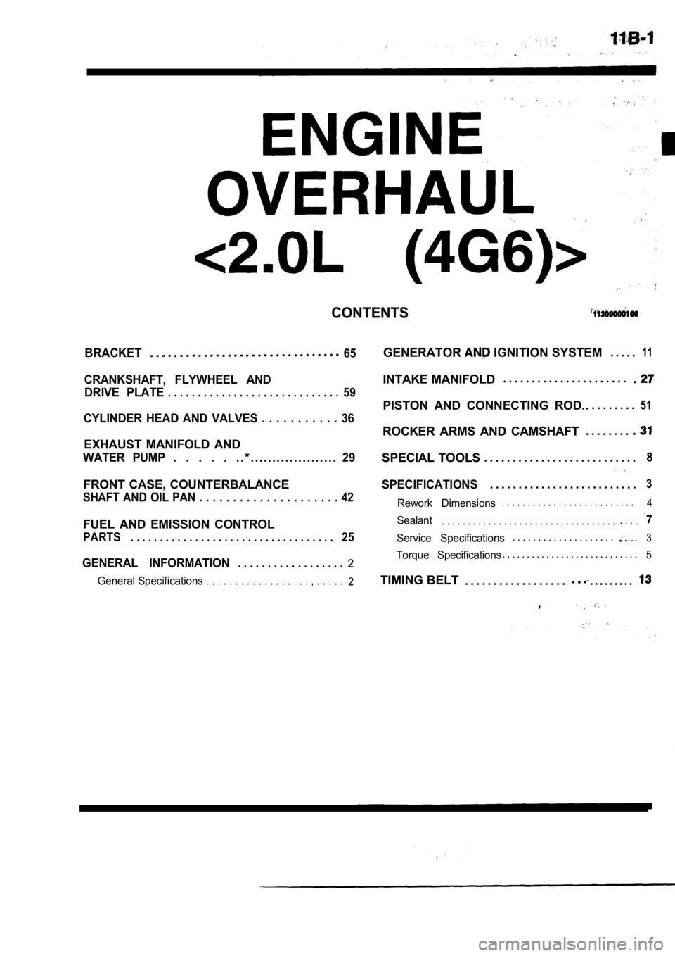
BRACKET65
CRANKSHAFT, FLYWHEEL ANDDRIVE PLATE
. . . . . . . . . . . . . . . . . . . . . . . . . . . . .59
CYLINDER HEAD AND VALVES . . . . . . . . . . . 36
EXHAUST MANIFOLD AND
WATER PUMP. . . . . . . * . . . . . . . . . . . . . . . . . . . .29
FRONT CASE, COUNTERBALANCE
SHAFT AND OIL PAN . . . . . . . . . . . . . . . . . . . . . 42
FUEL AND EMISSION CONTROL
PARTS. . . . . . . . . . . . . . . . . . . . . . . . . . . . . . . . . . .25
GENERAL INFORMATION. . . . . . . . . . . . . . . . . .2
General Specifications . . . . . . . . . . . . . . . . . . , . . . . .2
GENERATOR IGNITION SYSTEM. . . . .11
INTAKE MANIFOLD. . . . . . . . . . . . . . . . . . . . . .
PISTON AND CONNECTING ROD..
. . . . . . . .51
ROCKER ARMS AND CAMSHAFT. . . . . . . .
SPECIAL TOOLS
. . . . . . . . . . . . . . . . . . . . . . . . . . .8
SPECIFICATIONS. . . . . . . . . . . . . . . . . . . . . . . . . .3
Rework Dimensions. . . . . . . . . . . . . . . . . . . . . . . . . .4
Sealant. . . . . . . . . . . . . . . . . . . . . . . . . . . . . . . . . .. . ..
Service Specifications. . . . . . . . . . . . . . . . . . . ....3
Torque Specifications. . . . . . . . . . . . . . . . . . . . . . . . . . . .5
TIMING BELT
. . . . . . . . . . . . . . . . . .. . . . . . . . .
,
Page 107 of 2103
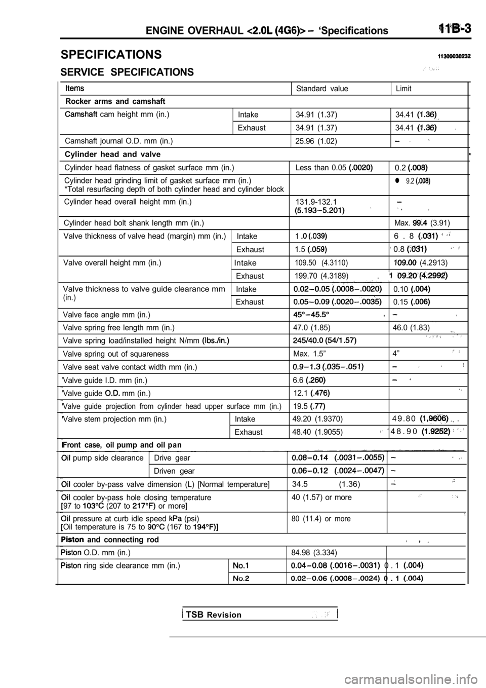
ENGINE OVERHAUL ‘Specifications
SPECIFICATIONS
SERVICE SPECIFICATIONS
Rocker arms and camshaft
cam height mm (in.)
Camshaft journal O.D. mm (in.)
Cylinder head and valve
Standard valueLimit
Intake 34.91 (1.37) 34.41
Exhaust 34.91 (1.37) 34.41
25.96 (1.02)
Cylinder head flatness of gasket surface mm (in.) Le ss than 0.05 0.2
Cylinder head grinding limit of gasket surface mm (in.)l 9.2
*Total resurfacing depth of both cylinder head and cylinder block
Cylinder head overall height mm (in.) 131.9-132.1
Cylinder head bolt shank length mm (in.) Max. (3.91)
Valve thickness of valve head (margin) mm (in.) Intake
16 . 8
Exhaust1.5 0.8
Valve overall height mm (in.)Intake109.50 (4.3110) (4.2913)
Exhaust 199.70 (4.3189)
.
Valve thickness to valve guide clearance mmIntake0.10
(in.)Exhaust0.15
Valve face angle mm (in.),
Valve spring free length mm (in.) 47.0 (1.85) 46.0 (1
.83)
Valve spring load/installed height N/mm
Valve spring out of squarenessMax. 1.5”4”
Valve seat valve contact width mm (in.)
Valve guide I.D. mm (in.) 6.6
Valve guide mm (in.)12.1
Valve guide projection from cylinder head upper sur
face mm (in.)19.5
Valve stem projection mm (in.) Intake 49.20 (1.9370)4 9 . 8 0 .
Exhaust48.40 (1.9055) ‘ 4 8 . 9 0
Front case, oilpump and oilp a n
pump side clearance Drive gear
Driven gear
cooler by-pass valve dimension (L) [Normal tempera
ture]34.5 (1.36)
cooler by-pass hole closing temperature 40 (1.57) or more
97 to (207 to or more]
pressure at curb idle speed (psi)80 (11.4) or more
Oil temperature is 75 to (167 to
and connecting rod ,
O.D. mm (in.)
84.98 (3.334)
ring side clearance mm (in.) 0 . 1
0 . 1
TSB Revision