Page 74 of 2103

ENGINE On-vehicle Service
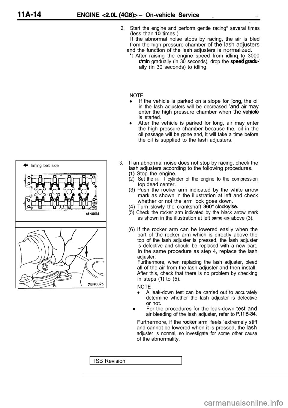
Timing belt side
.
2.Start the engine and perform gentle racing* several times
(less than times.)
If the abnormal noise stops by racing, the air is b led
from the high pressure chamber of the lash adjusters
and the function of the lash adjusters is normalized.
After raising the engine speed from idling to 3000
gradually (in 30 seconds), drop the
ally (in 30 seconds) to idling.
NOTE
lIf the vehicle is parked on a slope for the oil
in the lash adjusters will be decreased ‘andairmay
enter the high pressure chamber when the
is started.
lAfter the vehicle is parked for long, air may enter
the high pressure chamber because the, oil in the
oil passage will be gone and, it will take a time b efore
the oil is supplied to the lash adjusters.
3.If an abnormal noise does not stop by racing, check the
lash adjusters according to the following procedure s.
Stop the engine.
(2)Set the NG. cylinder of the engine to the compression
top dead center.
(3) Push the rocker arm indicated by the white arro w
mark as shown in the illustration at left and check
whether or not the arm lock goes down.
(4) Turn slowly the crankshaft
(5) Check the rocker arm indicated by the black arr ow mark
as shown in the illustration at left above (3).
(6) If the rocker arm can be lowered easily when th e
part of the rocker arm which is directly above the
top of the lash adjuster is pressed, the lash adjus ter
is defective and should be replaced with a new part .
In the same procedure as step 4, replace the lash
adjuster.
Furthermore, when replacing the lash adjuster, bleed
all of the air from the lash adjuster and then install.
After this, check that there is no problem by check ing
in steps to (5).
NOTE
lA leak-down test can be carried out to accurately
determine whether the lash adjuster is defective
or not.
l For the procedures for the leak-down test and
air bleeding of the lash adjuster, refer to
Furthermore, if the arm’ feels ‘extremely stiff
and cannot be lowered when it is pressed, the lash
adjuster is normal, so investigate for some other c ause
of the abnormality.
TSB Revision
Page 76 of 2103

ENGINE Engine
ENGINE ASSEMBLY
REMOVAL AND INSTALLATION
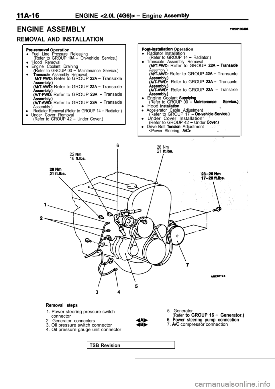
Operationl Fuel Line Pressure Releasing(Refer to GROUP On-vehicle Service.)l ‘Hood Removall Engine Coolant DrainingRefer to GROUP 00 Maintenance Service.)l Assembly Removal Refer to GROUP TransaxleA Refer to GROUP Transaxle
Refer to GROUP Transaxle
Refer to GROUP TransaxleAssembly.)lRadiator Removal (Refer to GROUP 14 Radiator.)l Under Cover Removal (Refer to GROUP 42 Under Cover.)
6
2216
Operationl Radiator Installation(Refer to GROUP 14 Radiator.)l Transaxle Assembly Removal Refer to GROUP Assembly.) Refer to GROUP Transaxle
Refer to GROUP Transaxle
Refer to GROUP
Transaxle
l Engineoolant(Refer to GROUP 00 l Hoodl Accelerator Cable Adjustment(Refer to GROUP 17 l Under Cover Installation(Refer to GROUP 42 Under l Drive Belt Adjustment
26 Nm21
34
Removal steps
1. Power steering pressure switchconnector
2. Generator connectors
3. Oil pressure switch connector
4. Oil pressure gauge unit connector
5. Generator(Referto GROUP 16 Generator.)
6. Power steering pump connection7. compressor connection
TSB Revision
Page 78 of 2103
ENGINE Assemblv
6749
4 4
3325
Nm72-67
49 Nm
36
30. Front exhaust pipe connection31. Gasket 32. Engine mount bracket assembly 33. Engine assembly
REMOVAL SERVICE POINTS
POWER STEERING PUMP
Remove the power steering pump from with the
hose attached..
NOTE
Place the removed power steering pump in a‘place where
it will not be a hindrance when
and installing the
engine assembly, and tie it
a cord.
TSB Revision
Page 79 of 2103

ENGINE -‘Engine Assembly
COMPRESSOR
Disconnect the compressor connector and remove the
compressor from the compressor bracket
the hose
attached.
NOTE
Place the removed A/C compressor in a where it will
not be a hindrance when removing ‘and installing th e engine
assembly, and tie it with a cord:
Caution
Do not bend the joint the A/C hose and the
pipe by force.
ENGINE MOUNT BRACKET ASSEMBLY
REMOVAL
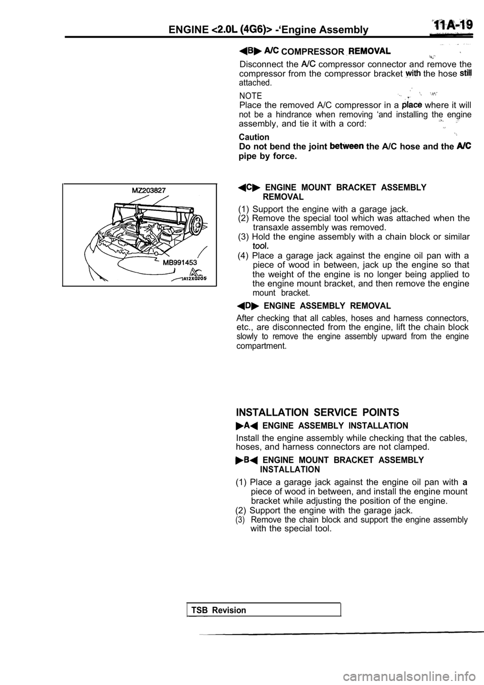
(1) Support the engine with a garage jack.
(2) Remove the special tool which was attached when the
transaxle assembly was removed.
(3) Hold the engine assembly with a chain block or similar
(4) Place a garage jack against the engine oil pan with a
piece of wood in between, jack up the engine so tha t
the weight of the engine is no longer being applied to
the engine mount bracket, and then remove the engin e
mount bracket.
ENGINE ASSEMBLY REMOVAL
After checking that all cables, hoses and harness connectors,
etc., are disconnected from the engine, lift the chain block
slowly to remove the engine assembly upward from th e engine
compartment.
INSTALLATION SERVICE POINTS
ENGINE ASSEMBLY INSTALLATION
Install the engine assembly while checking that the cables,
hoses, and harness connectors are not clamped.
ENGINE MOUNT BRACKET ASSEMBLY
INSTALLATION
(1) Place a garage jack against the engine oil pan with a
piece of wood in between, and install the engine mo unt
bracket while adjusting the position of the engine.
(2) Support the engine with the garage jack.
(3)Remove the chain block and support the engine assem bly
with the special tool.
TSB Revision
Page 83 of 2103
ENGINECamshaft and Camshaft ‘Oil -Seal
Removal steps
1. Accelerator cable connection2.Center cover
3. Spark plug cable
4.Breather hose5.PCV6.Rocker cover7. Timing belt (Refer to 8.Cover9.Gasket10. Camshaft position sensing cylinder 11. Camshaft position sensor support
12. Exhaust camshaft sprocket
13. Intake camshaft sprocket
14. Front camshaft bearing cap
15.Camshaft bearing cap
16. Rear camshaft bearing cap (R.H.)
17. Rear camshaft bearing cap (L.H.)
18.Exhaust camshaft19.Intake camshaft20. Camshaft oil seal21.Semi-circular packing
Installation steps. .
19. Intake camshaft 18. Exhaust camshaft Rear cap (R.H.)
16. Rear bearing cap (L.H.)
15. bearing cap 14. bearing cap
20. Camshaft 13. Intake camshaft12. Exhaust 11. Camshaft
Cover
7. Timing belt (Refer to
21. Semi-circular packing”
6. Rocker cover hose
4. Breather hose
3. Spark plug, cable2. Center cover 1. Accelerator cable .
Service.)
TSBRevision
Page 84 of 2103

ENGINECamshaft and Camshaft Oil
Plastic hammer
sideExhaust side
Slits01
Dowel pins
ExhaustsideIntake side
I
REMOVAL SERVICE POINTS .
EX H A UST
CAMSHAFT SPROCKET
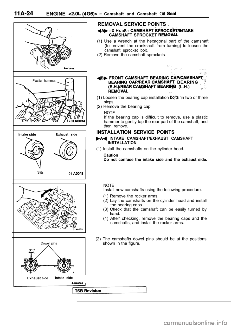
Use a wrench at the hexagonal part of the camshaft
(to prevent the crankshaft from turning) to loosen the
camshaft sprocket bolt.
(2) Remove the camshaft sprockets.
FRONT CAMSHAFT BEARING FRONT CAMSHAFT BEARING
B E A R I N G B E A R I N G
(L.H.) (L.H.)
(1) Loosen the bearing cap installation ‘in two or three
steps.
(2) Remove the bearing cap.
NOTE
If the bearing cap is difficult to remove, use a plastic
hammer to gently tap the rear part of the camshaft, and
then remove.
INSTALLATION SERVICE POINTS
INTAKE CAMSHAFT/EXHAUST CAMSHAFT
INSTALLATION
(1) Install the camshafts on the cylinder head.
Caution
Do not confuse the intake side and the exhaust side .
NOTE
Install new camshafts using the following procedure.
(1) Remove the rocker arms.
(2) Lay the camshafts on the cylinder head and inst all
the bearing caps.
(3)
that the camshaft can be easily turned by
(4) After’ checking, remove the bearing caps and th e
camshafts, and install the rocker arms.
(2) The camshafts dowel pins should be at the posit ions
shown in the figure.
Page 87 of 2103
ENGINE Oil and
Oil pan side
R E M O V A L
(1) Remove the transfer
shaft still installed..
(2) Insert a flat-tipped screwdriver or similar
the transfer and transaxle, and remove transfer
the center shaft. .
(3) Remove the transfer from the propeller shaft.
Caution
Do not tilt the transfer assembly to the rear, or t ransfer
oil will leak out.
(4) After removing the transfer assembly, insert th e special
tool to prevent ‘the
oil from leaking out.
(5) Suspend the shaft from the vehicle chassis with
wire: etc.
PAN
After removing the oil pan mounting bolts; oil
pan with the special tool and a brass bar.
Caution
Do it slowly to avoid of the
INSTALLATION SERVICE POINTS
OIL PAN INSTALLATION
Caution
After cleaning the oil pan mounting bolt holes in t he oil
seal case, the oil pan should be fnstalled.
GASKET INSTALLATION
Replace the gasket and install it in the direction shown in
the illustration.
TSB Revision. . .
Page 88 of 2103
ENGINECrankshaft Front Oil’
CRANKSHAFT FRONT OIL SEAL11333343133
REMOVAL AND INSTALLATION
and Post-installation Operationl Timing Belt Removal and installation
(Refer to
Removal steps
1. Crankshaft sprocket
front oil seal
INSTALLATION SERVICE
FRONT OIL SEAL
(1) Apply engine oil to the entire inside diameter of the oil
seal lip.
(2) Press-fit the oil seal until it is flush with the oil
case.