1990 MITSUBISHI SPYDER service
[x] Cancel search: servicePage 55 of 2103
G E N E R A L Maintenance
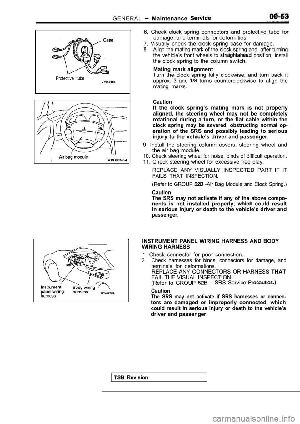
Protective tube
harness
6. Check clock spring connectors and protective tube for
damage, and terminals for deformities.
7. Visually check the clock spring case for damage.
8.Align the mating mark of the clock spring and, afte r turning
the vehicle’s front wheels to
position, install
the clock spring to the column switch.
Mating mark alignment
Turn the clock spring fully clockwise, and turn bac k it
approx. 3 and
turns counterclockwise to align the
mating marks.
Caution
If the clock spring’s mating mark is not properly
aligned, the steering wheel may not be completely
rotational during a turn, or the flat cable within the
clock spring may be severed, obstructing normal op-
eration of the SRS and possibly leading to serious
injury to the vehicle’s driver and passenger.
9. Install the steering column covers, steering whe el and
the air bag module.
10. Check steering wheel for noise, binds of diffic ult operation.
11. Check steering wheel for excessive free play.
REPLACE ANY VISUALLY INSPECTED PART IF IT
FAILS THAT INSPECTION.
(Refer to GROUP
-Air Bag Module and Clock Spring.)
Caution
The SRS may not activate if any of the above compo-
nents is not installed properly, could result
in serious injury or death to the vehicle’s driver and
passenger.
INSTRUMENT PANEL WIRING HARNESS AND BODY
WIRING HARNESS
1. Check connector for poor connection.
2.Check harnesses for binds, connectors for damage, a nd
terminals for deformations.
REPLACE ANY CONNECTORS OR HARNESS THAT
FAIL THE VISUAL INSPECTION.
(Refer to GROUP
SRS Service
Caution
The SRS may not activate if SRS harnesses or connec -
tors are damaged or improperly connected, which
could result in serious injury or death to the vehicle’s
driver and passenger.
Revision
Page 56 of 2103
GENERAL Maintenance Service;
Revision
22. EXHAUST SYSTEM (CONNECTION
OF MUFFLER, PIPINGS AND, CONVERTER
HEAT SHIELDS) (Check
as’
required)
1.Check for holes and gas leaks’dwe to damage;
etc.
2.Check the joints and connections for looseness and gas’
leaks.
3. Check the hanger rubber and brackets for damage.
Page 61 of 2103
ENGINE
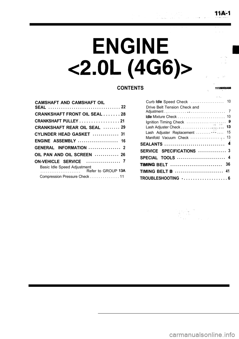
CONTENTS
CAMSHAFT AND CAMSHAFT OIL
SEAL. . . . . . . . . . . . . . . . . . . . . . . . . . . . . . . . . .22
CRANKSHAFT FRONT OIL SEAL . . . . . . . 28
CRANKSHAFT PULLEY . . . . . . . . . . . . . . . . . 21
CRANKSHAFT REAR OIL SEAL. . . . . . . .29
Curb Speed Check. . . . . . . . . . . . . . . . . .10
Drive Belt Tension Check and
Adjustment . , . . . . . . . . . . . . . . . . . . . . . . . . . . . 7
Mixture Check . . . . . . . . . . . . . . . . . .
. . . . .10
Ignition Timing Check. . . . . . . . . . . .. . . . . . . . .
Lash Adjuster Check . . . . . . . . . . . . . . . .
CYLINDER HEAD GASKET . . . . . . . . . . . . .31
ENGINE ASSEMBLY. . . . . . . . . . . . . . . . . . . .16
GENERAL INFORMATION. . . . . . . . . . . . . . . .2
OIL PAN AND OIL SCREEN . . . . . . . . . . . .26
ON-VEHICLE SERVICE. . . . . . . . . . . . . . . . .7
Basic Idle Speed Adjustment
. . . . . . . . . . . . . . . . . . . . . . Refer to GROUP
Lash Adjuster Replacement. . . . . . . .. . . .15
Manifold Vacuum Check. . . . . . . . . . . . . . . ....13
SEALANTS. . . . . . . . . . . . . . . . . . . . . . . . . . . . . .
SERVICE SPECIFICATIONS. . . . . . . . . . . . . .3
SPECIAL TOOLS. . . . . . . . . . . . . . . . . . . . . . . .4
BELT. . . . . . . . . . . . . . . . . . . . . . . . . . .36
TIMING BELT . . . . . . . . . . . . . . . . . . . . . . . .41
Compression Pressure Check . . . . . . . . . . . .
. . 11TROUBLESHOOTING . . . . . . . . . . . . . . . . . . . 6
Page 63 of 2103
ENGINE Service Specifications
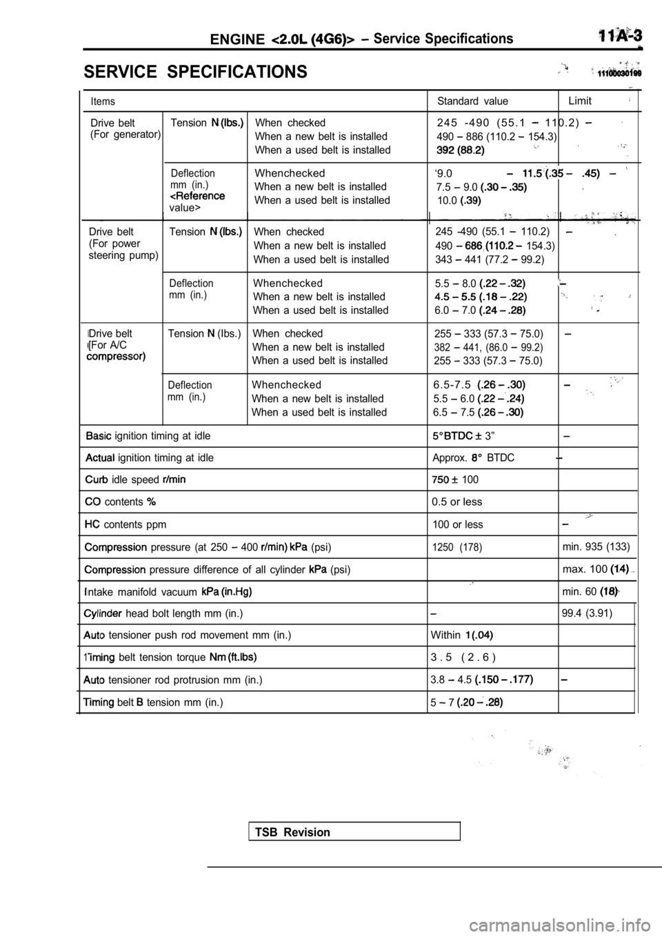
SERVICE SPECIFICATIONS
I
1
Items
Drive beltTensionWhen checked
(For generator) When a new belt is installed
When a used belt is installed
DeflectionWhenchecked
mm (in.)When a new belt is installed
value>When a used belt is installed
Drive belt Tension
When checked
(For power When a new belt is installed
steering pump) When a used belt is installed
DeflectionWhenchecked
mm (in.)When a new belt is installed
When a used belt is installed
Drive belt Tension
(Ibs.) When checked
[For A/C When a new belt is installed
When a used belt is installed
DeflectionWhenchecked
mm (in.)When a new belt is installed
When a used belt is installed
ignition timing at idle
ignition timing at idle
idle speed
contents
contents ppm
pressure (at 250 400 (psi)
pressure difference of all cylinder (psi)
ntake manifold vacuum
head bolt length mm (in.)
tensioner push rod movement mm (in.)
belt tension torque
tensioner rod protrusion mm (in.)
belt tension mm (in.)
Standard valueLimit
2 4 5 - 4 9 0 ( 5 5 . 1 1 1 0 . 2 )
490 886 (110.2 154.3)
‘9.0
7.5 9.0
10.0
.245 -490 (55.1 110.2)
490 154.3)
343
441 (77.2 99.2)
5.5
8.0
6.0 7.0
255 333 (57.3 75.0)
382 441, (86.0 99.2)
255 333 (57.3 75.0)
6 . 5 - 7 . 5
5.5 6.0
6.5 7.5
3”
Approx. BTDC
100
0.5 or less
100 or less
1250 (178)min. 935 (133)
max. 100
min. 60
99.4 (3.91)
Within
3 . 5 ( 2 . 6 )
3.8 4.5
5 7
TSB Revision
Page 65 of 2103
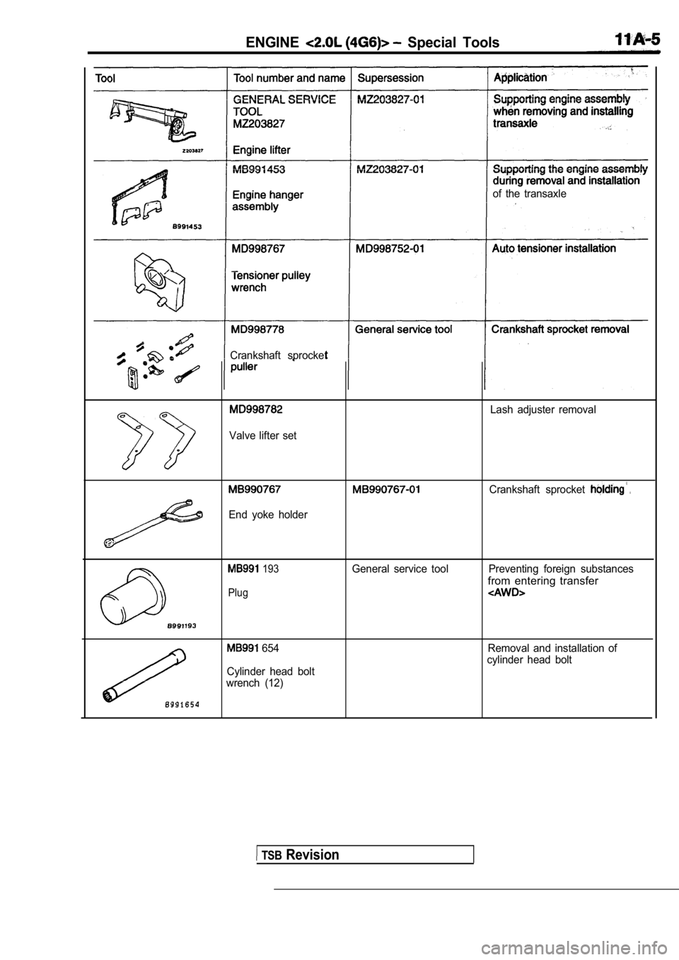
ENGINE Special Tools
of the transaxle
Crankshaft sprocket
Lash adjuster removal
Valve lifter set
. .
End yoke holder
Crankshaft sprocket
193General service tool Preventing foreign substances
from entering transfer
Plug
654
Cylinder head bolt
wrench (12) Removal and installation of
cylinder head bolt
TSB Revision
Page 68 of 2103
ENGINE On-vehicle Service
pump pulley
Cranksh
pulley
pulley
a
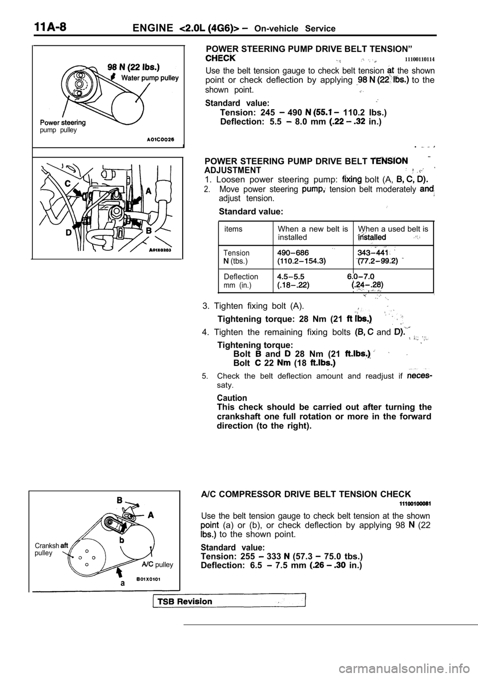
POWER STEERING PUMP DRIVE BELT TENSION”
11100110114
Use the belt tension gauge to check belt tension the shown
point or check deflection by applying to the
shown point.
Standard value:
Tension: 245 490 110.2 Ibs.)
Deflection: 5.5
8.0 mm in.)
.
POWER STEERING PUMP DRIVE BELT
ADJUSTMENT
1. Loosen power steering pump: bolt (A,
2.Move power steering tension belt moderately
adjust tension.
Standard value:
items
Tension
(tbs.)
Deflection
mm (in.)
When a new belt is When a used belt is installed
,,
3. Tighten fixing bolt (A).
Tightening torque: 28 Nm (21
4. Tighten the remaining fixing bolts and
Tightening torque:
Bolt and 28 Nm (21
Bolt 22 (18
5.Check the belt deflection amount and readjust if
saty.
Caution
This check should be carried out after turning the
crankshaft one full rotation or more in the forward
direction (to the right).
A/C COMPRESSOR DRIVE BELT TENSION CHECK
Use the belt tension gauge to check belt tension at the shown
(a) or (b), or check deflection by applying 98 (22
to the shown point.
Standard value:
Tension: 255 333 (57.3 75.0 tbs.)
Deflection: 6.5
7.5 mm in.)
Page 70 of 2103
ENGINE On-vehicle Service
NOTE
1.Ignition timing is variable within about even under
operating.
2. And it is automatically further advanced by abou t
from BTDC at higher altitudes.
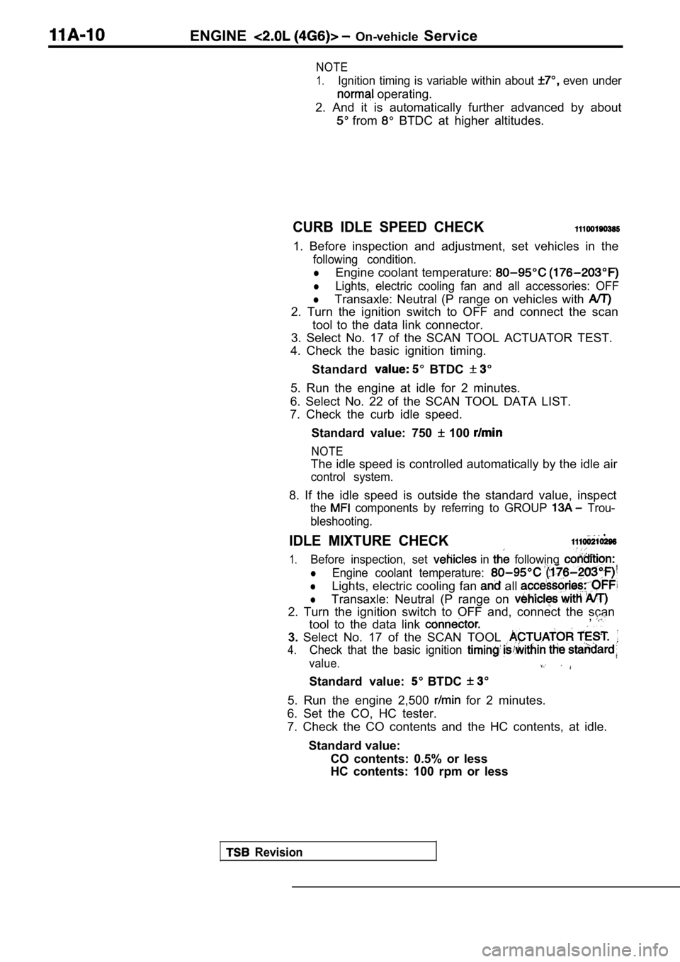
CURB IDLE SPEED CHECK
1. Before inspection and adjustment, set vehicles in the
following condition.
lEngine coolant temperature:
lLights, electric cooling fan and all accessories: OFF
lTransaxle: Neutral (P range on vehicles with
2. Turn the ignition switch to OFF and connect the scan
tool to the data link connector.
3. Select No. 17 of the SCAN TOOL ACTUATOR TEST.
4. Check the basic ignition timing.
Standard
BTDC
5. Run the engine at idle for 2 minutes.
6. Select No. 22 of the SCAN TOOL DATA LIST.
7. Check the curb idle speed.
Standard value: 750
100
NOTE
The idle speed is controlled automatically by the i dle air
control system.
8. If the idle speed is outside the standard value, inspect
the components by referring to GROUP Trou-
bleshooting.
IDLE MIXTURE CHECK .
1.Before inspection, set in following
lEngine coolant temperature:
lLights, electric cooling fan all
lTransaxle: Neutral (P range on
2. Turn the ignition switch to OFF and, connect the scan
tool to the data link ,
3. Select No. 17 of the SCAN TOOL
4.Check that the basic ignition
value.
Standard value: BTDC
5. Run the engine 2,500 for 2 minutes.
6. Set the CO, HC tester.
7. Check the CO contents and the HC contents, at id le.
Standard value: CO contents: 0.5% or less
HC contents: 100 rpm or less
Revision
Page 73 of 2103
ENGINE On-vehicle Service
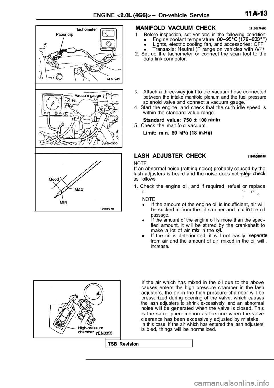
MANIFOLD VACUUM CHECK11100270200
1.Before inspection, set vehicles in the following condition:
lEngine coolant temperature:
lLights, electric cooling fan, and accessories: OFF
l Transaxle: Neutral (P range on vehicles with
2. Set up the tachometer or connect the scan tool t o the
data link connector.
3.Attach a three-way joint to the vacuum hose connect ed
between the intake manifold plenum and the fuel pressure
solenoid valve and connect a vacuum gauge.
4. Start the engine, and check that the curb idle s peed is
within the standard value range.
Standard value: 750
100
5. Check the manifold vacuum.
Limit: min. 60
(18
LASH ADJUSTER CHECK
NOTE
NOTE
If an abnormal noise (rattling noise) probably caus ed by the
If an abnormal noise (rattling noise) probably caus ed by the
lash adjusters is heard and the noise does not
lash adjusters is heard and the noise does not
as follows.
as follows.
1. Check the engine oil, and if required, refuel or replace
it.
NOTE
lIf the amount of the engine oil is insufficient, ai r will
be sucked in from the oil strainer and mix
the oil
passage.
lIf the amount of the engine oil is more than the sp eci-
fied amount, it will be stirred by the crankshaft to
make a lot of air
in the
l If the oil is deteriorated, it will not easily
from air and the amount of air’ mixed in the oil wi ll ,
increase.
If the air which has mixed in the oil due to the ab ove
causes enters the high pressure chamber in the lash
adjusters, the air in the high pressure chamber wil l be
pressurized during opening of the valve, which caus es
the lash adjusters to shrink excessively, and an abnormal
noise will be generated when the valve is closed. T his
is the same phenomenon as the one when the valve
clearance has been excessively adjusted by mistake.
In this case, if the air which has entered the lash adjusters
is bled, things will be normalized.
TSB Revision