1990 MITSUBISHI SPYDER service
[x] Cancel search: servicePage 159 of 2103
ENGINE OVERHAUL and
CrankshaftUpper side
side
ring gap and spacer gaprail
Timing belt side
Front mark
Identification mark
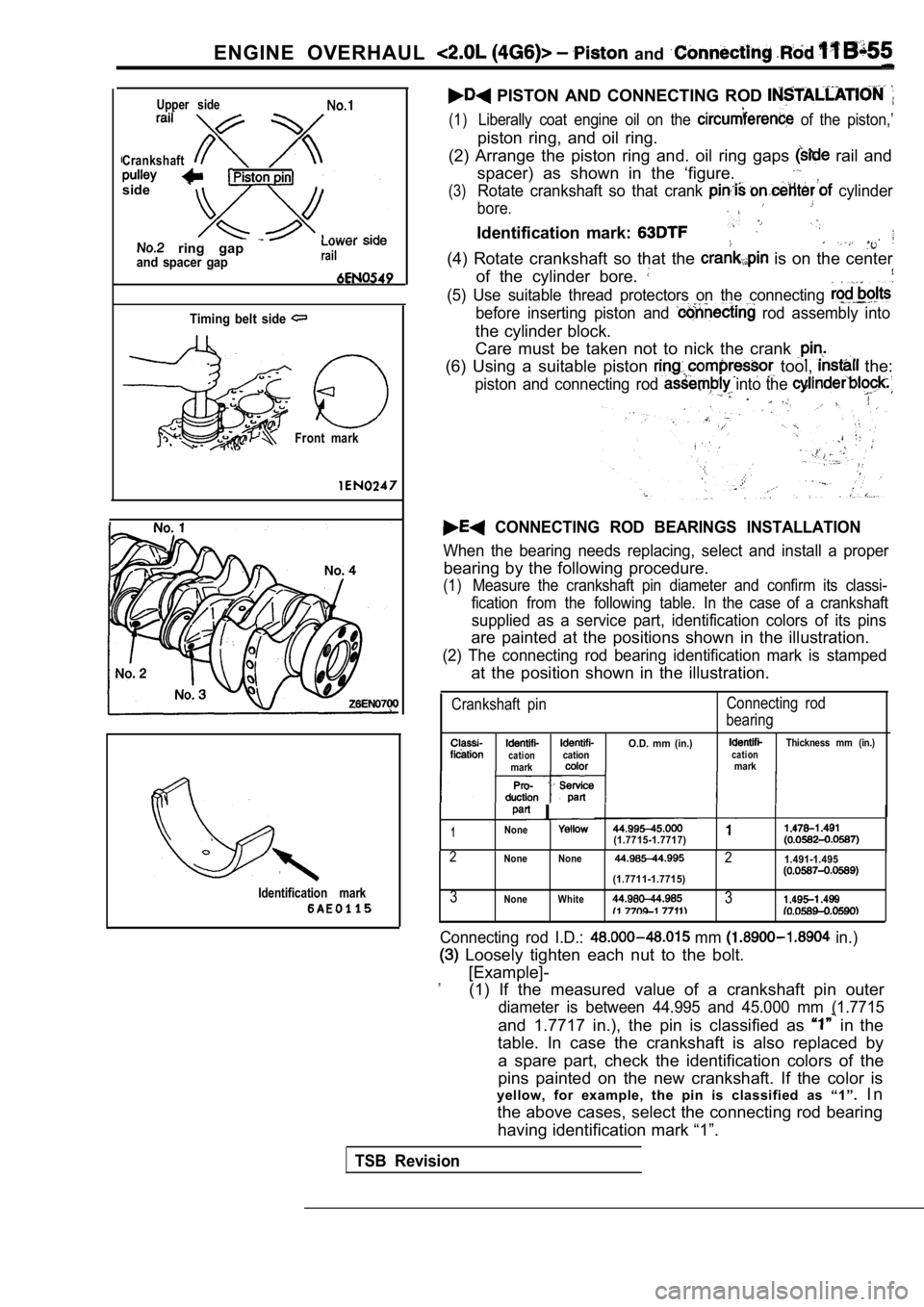
PISTON AND CONNECTING ROD
(1)Liberally coat engine oil on the of the piston,’
piston ring, and oil ring.
(2) Arrange the piston ring and. oil ring gaps
rail and
spacer) as shown in the ‘figure.
(3)Rotate crankshaft so that crank cylinder
bore.
Identification mark:
(4) Rotate crankshaft so that the is on the center
of the cylinder bore.
(5) Use suitable thread protectors on the connectin g
before inserting piston and rod assembly into
the cylinder block.
Care must be taken not to nick the crank
(6) Using a suitable piston tool, the:
piston and connecting rod into the ,
CONNECTING ROD BEARINGS INSTALLATION
When the bearing needs replacing, select and instal l a proper
bearing by the following procedure.
(1)Measure the crankshaft pin diameter and confirm its classi-
fication from the following table. In the case of a crankshaft
supplied as a service part, identification colors of its pins
are painted at the positions shown in the illustrat ion.
(2) The connecting rod bearing identification mark is stamped
at the position shown in the illustration.
Crankshaft pinConnecting rod
bearing
O.D. mm (in.)Thickness mm (in.)cationcationcationmarkmark
I
1None(1.7715-1.7717)
2None None21.491-1.495
(1.7711-1.7715)
3None White3
Connecting rod I.D.: mm in.)
Loosely tighten each nut to the bolt.
[Example]-
”(1) If the measured value of a crankshaft pin outer
diameter is between 44.995 and 45.000 mm (1.7715
and 1.7717 in.), the pin is classified as in the
table. In case the crankshaft is also replaced by
a spare part, check the identification colors of th e
pins painted on the new crankshaft. If the color is
yellow, for example, the pin is classified as “1”. I n
the above cases, select the connecting rod bearing having identification mark “1”.
TSB Revision
Page 164 of 2103
11
Crankshaft,
ENGINE OVERHAUL Drive Plate .
Timing belt side
Cylinder block bearing
bore identification mark
R E M O V A L POINT
JET
Use an appropriate metal bar to press the out.
(1) Be careful not to damage the cylinder
(2) Never reuse the removed oil
INSTALLATION SERVICE POINTS
JET INSTALLATION
Use a pin punch of 4
5 mm in.) diameter to
press the oil jet in from the crank journal until t he oil jet bottoms
on.
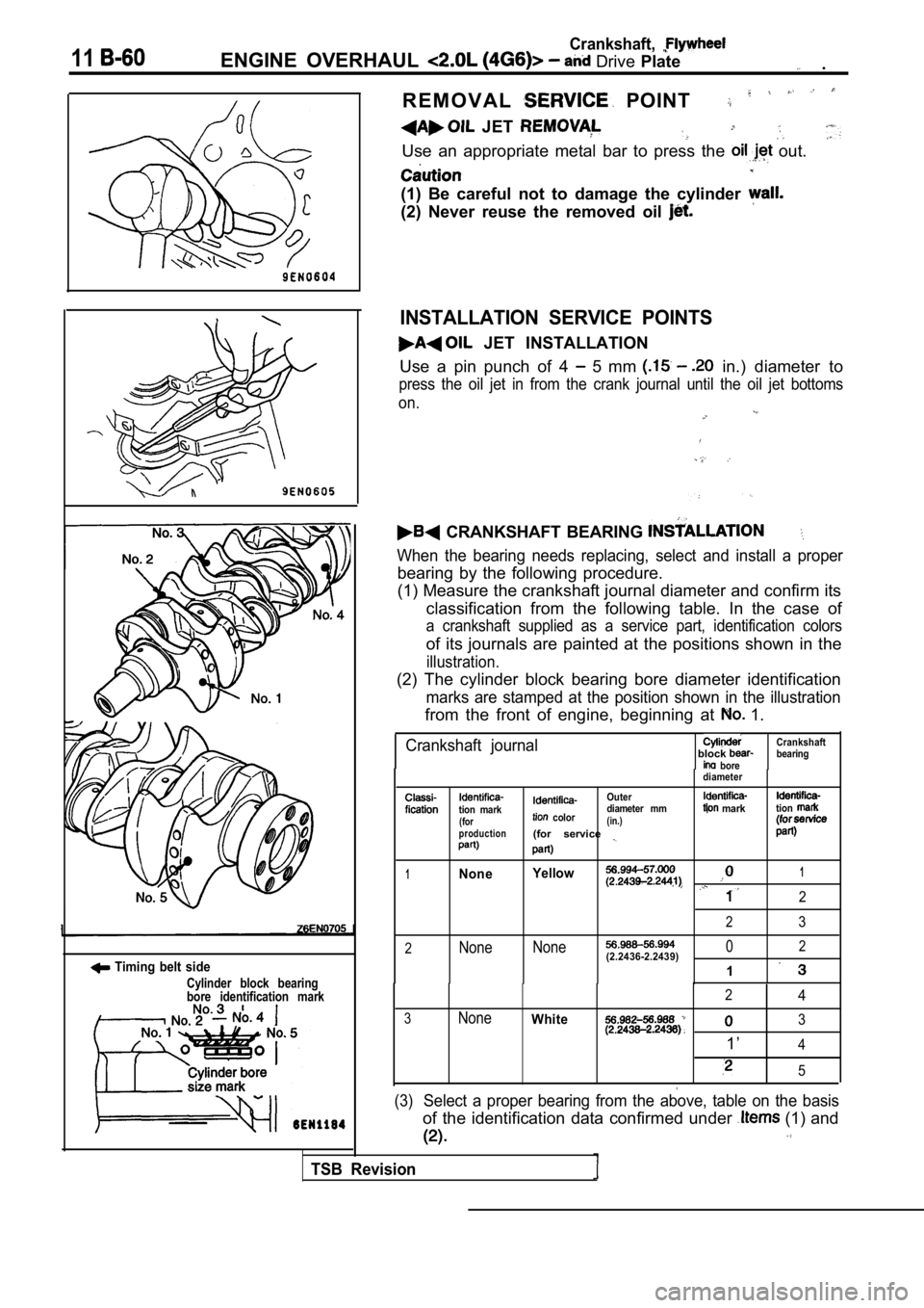
CRANKSHAFT BEARING
When the bearing needs replacing, select and instal l a proper
bearing by the following procedure.
(1) Measure the crankshaft journal diameter and confirm its
classification from the following table. In the cas e of
a crankshaft supplied as a service part, identification colors
of its journals are painted at the positions shown in the
illustration.
(2) The cylinder block bearing bore diameter identi fication
marks are stamped at the position shown in the illustration
from the front of engine, beginning at 1.
Crankshaft journalblock bore
diameter Crankshaft
bearing
tion mark(for
production
Outer
color diameter mm(in.)(for service
marktion
1None
Yellow1
2
23
2None
None02(2.2436-2.2439)
1
24
3NoneWhite3
1’4
5
(3)Select a proper bearing from the above, table on th
e basis
of the identification data confirmed under (1) and
TSB Revision
Page 171 of 2103
CONTENTS
CAMSHAFT AND CAMSHAFT OIL
SEAL. . . . . . . . . . . . . . . . . . . . . . . . . . . . . . . . . . . . .21
CRANKSHAFT FRONT OIL SEAL. . . . . . . . . .25
CRANKSHAFT PULLEY. . . . . . . . . . . . . . . . . . .19
CRANKSHAFT REAR OIL SEAL
. . . . . . . . . .
CYLINDER HEAD GASKET. . . . . . . . . . . . . . . .29
ENGINE ASSEMBLY. . . . . . . . . . . . . . . . . . . . . .14
GENERAL INFORMATION. . . . . . . . . . . . . . . . . .2
OIL PAN AND OIL SCREEN . . . . . . . . . . . . . . .24
ON-VEHICLE SERVICE
. . . . . . . . . . . . . . . . . . . . .8
Basic idle Speed Adjustment. . . . . . . . . . . . . . . . . . . . . Refer to GROUP
Compression Pressure Check. . . . . . . . . ..
Curb Speed Check . . . . . . . . . ...
Drive Tension
Adjustment. . . . . . . . . . . . . . . . . . . . . . . . . . . . . . . . . . .
Mixture Check . . . . . . . . . . . . . . . . .. . . . . . ..
Ignition Timing Check. . . . . . . . .....................
Lash Adjuster Check . . . . . . . . . . . . . . . . .
......
. . . . .
Manifold Check . . . . . . . . . . . . .13
SEALANTS. . . . . . . . . . . . . . . . . . . . . . . . . . . . . . . .3
SERVICE SPECIFICATIONS. . . . . . . . . . . . . . . . .3
SPECIAL TOOLS. . . . . . . . . . . . . . . . . . . . . . . . . . .4
TIMING BELT. . . . . . . . . . . . . . . . . . . . . . . . . . . . .34
TROUBLESHOOTING. . . . . . . . . . . . . . . . . . . . . . .
7
Page 173 of 2103
ENGINE ‘Service
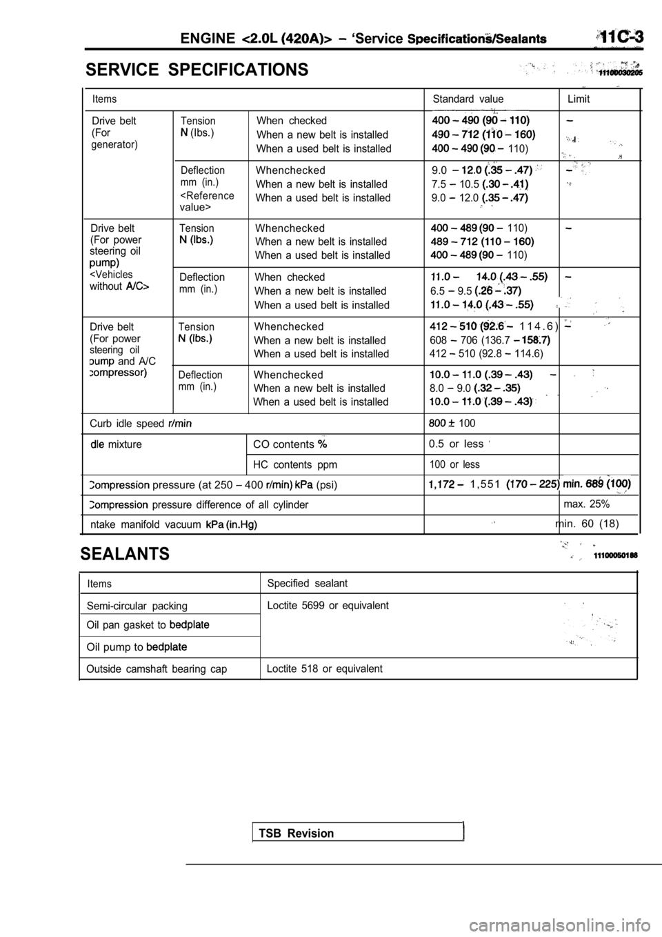
SERVICE SPECIFICATIONS
Items
Drive belt
(For
generator)
Standard value Limit
TensionWhen checked
(Ibs.) When a new belt is installed
When a used belt is installed
110)
DeflectionWhenchecked9.0
mm (in.)When a new belt is installed 7.5 10.5
Drive beltTensionWhenchecked
(For power
When a new belt is installed
steering oil
When a used belt is installed
mm (in.)When a new belt is installed
When a used belt is installed
Drive belt
TensionWhenchecked
(For power
When a new belt is installedsteering oil
and A/C When a used belt is installed
DeflectionWhenchecked
mm (in.)When a new belt is installed
When a used belt is installed
Curb idle speed
mixtureCO contents
HC contents ppm
pressure (at 250 400 (psi)
pressure difference of all cylinder
ntake manifold vacuum
110)
110)
6.5 9.5
1 1 4 . 6 )
608 706 (136.7
412 510 (92.8 114.6)
8.0 9.0
100
0.5 or less
100 or less
1 , 5 5 1
max. 25%
min. 60 (18)
SEALANTS
Items
Semi-circular packing
Oil pan gasket to
Oil pump to
Outside camshaft bearing cap Specified sealant
Loctite 5699 or equivalent
Loctite 518 or equivalent
TSB Revision
Page 175 of 2103
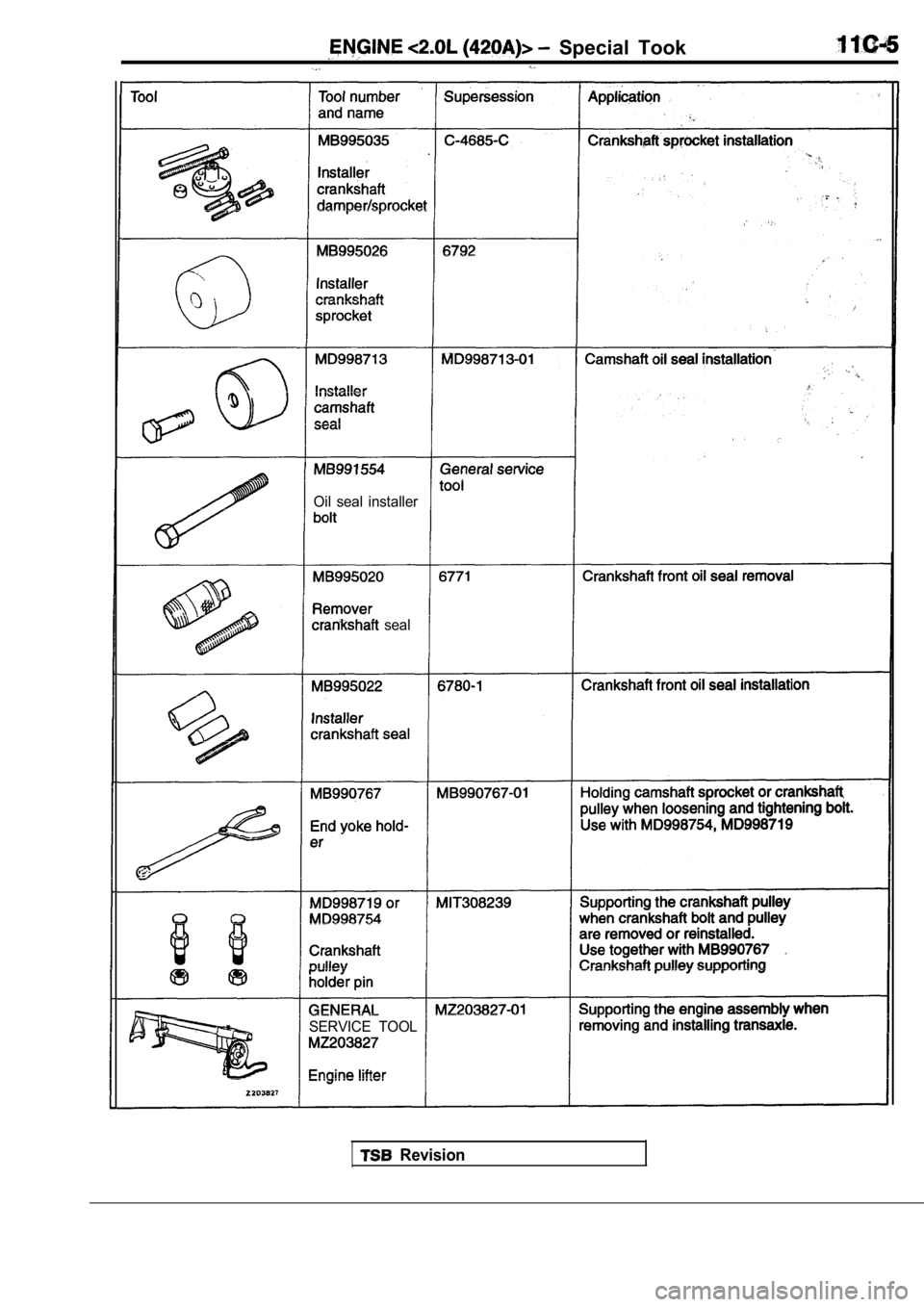
Special Took
Oil seal installer
seal
SERVICE TOOL
Revision
Page 180 of 2103
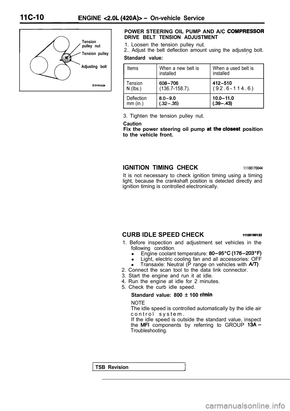
ENGINE On-vehicle Service
POWER STEERING OIL PUMP AND A/C
DRIVE BELT TENSION ADJUSTMENTTensionpulley nut1. Loosen the tension pulley nut.
Tension pulley2.. Adjust the belt deflection amount using the adj usting bolt.
Standard value:
Adjusting boltItems
Tension
(Ibs.)
Deflection
mm (in.) When a new belt is When a used belt is
installed
installed(136.7-158.7).( 9 2 . 6 - 1 1 4 . 6 )
3. Tighten the tension pulley nut.
Caution
Fix the power steering oil pump position
to the vehicle front.
IGNITION TIMING CHECK11100170044
It is not necessary to check ignition timing using a timing
light, because the crankshaft position is detected directly and
ignition timing is controlled electronically.
CURB IDLE SPEED CHECK
1. Before inspection and adjustment set vehicles in the
following condition.
lEngine coolant temperature:
lLight, electric cooling fan and all accessories: OF F
l Transaxle: Neutral (P range on vehicles with
2. Connect the scan tool to the data link connector .
3. Start the engine and run it at idle.
4. Run the engine at idle for 2 minutes.
5. Check the curb idle speed.
Standard value: 800
100
NOTE
The idle speed is controlled automatically by the i dle air
c o n t r o l s y s t e m . If the idle speed is outside the standard value, in spect
the
components by referring to GROUP
Troubleshooting.
TSB Revision
Page 181 of 2103

ENGINE On-vehicle Service
IDLE MIXTURE CHECK
11100210081
1.Before inspection, set vehicles in the following co ndition:
lEngine coolant temperature:
l Lights, electric cooling fan and all accessories: O FF
lTransaxle: Neutral (P range on vehicles with
2.After turning the ignition switch to OFF, connect t he scan
tool to the data link connector.
3.Start the engine and run it at 2,500 for 2 minutes.
4. Set the CO, HC tester.
5. Check the CO contents and the HC contents at idl e.
Standard value:
CO contents: 0.5% or less
HC contents: 100 ppm or less
6. If the idle speed is outside the standard value, check
the following items: l Diagnostic output
l Closed-loop control (When the closed-loop control
is carried out normally, the output signal of the h eated
oxygen sensor repeats between and
,000 at idle.)
l Fuel pressure
I n j e c t o r
lIgnition coil, spark plug cable, spark plug
lEGR system and the EGR valve leak
l Evaporative emission control system
Compression pressure
NOTE
Replace the three-way catalyst whenever the CO and
HC contents do not remain inside the standard value .
(even though the result of the inspection is normal on
all items.)
COMPRESSION PRESSURE CHECK
1.Before inspection, check that the engine oil, start er and
battery are normal. Also, set the vehicle to the fo llowing
condition:
lEngine coolant temperature:
lLights, electric cooling fan and all accessories: O FF
lTransaxle: Neutral (P range on vehicle with
2. Disconnect the spark plug cables.
3. Remove all spark plugs.
4.Disconnect the relay (ASD relay) connector to prevent
a spark.
4 4
Revision
Page 182 of 2103
E N G I N E On-vehicle Service’
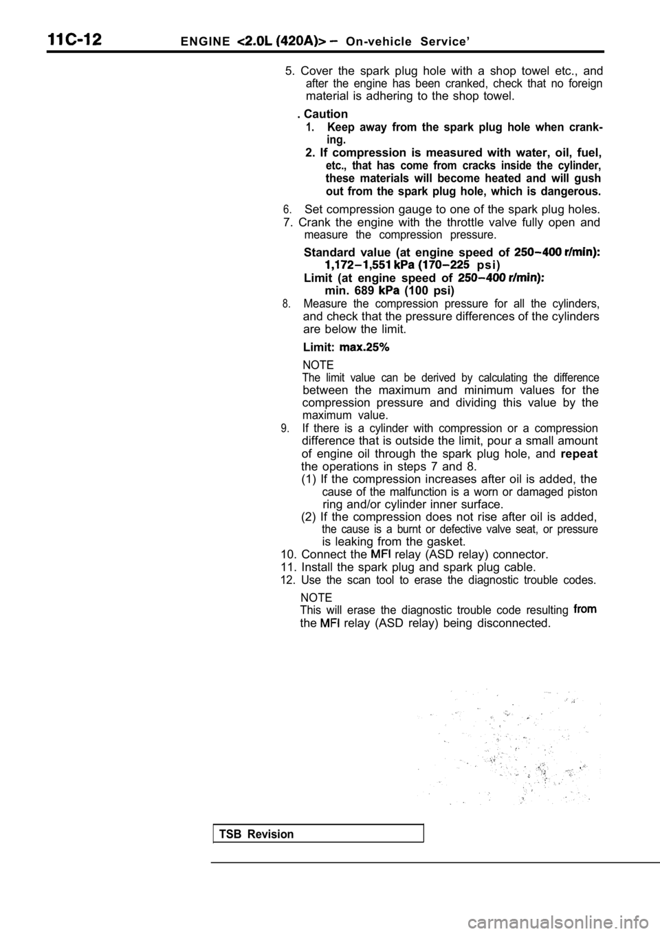
5. Cover the spark plug hole with a shop towel etc. , and
after the engine has been cranked, check that no foreign
material is adhering to the shop towel.
. Caution
1.Keep away from the spark plug hole when crank-
ing.
2. If compression is measured with water, oil, fuel ,
etc., that has come from cracks inside the cylinder ,
these materials will become heated and will gush
out from the spark plug hole, which is dangerous.
6.Set compression gauge to one of the spark plug hole s.
7. Crank the engine with the throttle valve fully o pen and
measure the compression pressure.
Standard value (at engine speed of
p s i )
Limit (at engine speed of
min. 689 (100 psi)
8.Measure the compression pressure for all the cylind ers,
and check that the pressure differences of the cylinders
are below the limit.
Limit:
NOTE
The limit value can be derived by calculating the d ifference
between the maximum and minimum values for the
compression pressure and dividing this value by the
maximum value.
9.If there is a cylinder with compression or a compre ssion
difference that is outside the limit, pour a small amount
of engine oil through the spark plug hole, and repeat
the operations in steps 7 and 8. (1) If the compression increases after oil is added , the
cause of the malfunction is a worn or damaged pisto n
ring and/or cylinder inner surface.
(2) If the compression does not rise after oil is a dded,
the cause is a burnt or defective valve seat, or pr essure
is leaking from the gasket.
10. Connect the
relay (ASD relay) connector.
11. Install the spark plug and spark plug cable.
12. Use the scan tool to erase the diagnostic troub le codes.
NOTE
This will erase the diagnostic trouble code resulti ng
the relay (ASD relay) being disconnected.
TSB Revision