1990 MITSUBISHI SPYDER coolant temperature
[x] Cancel search: coolant temperaturePage 391 of 2103

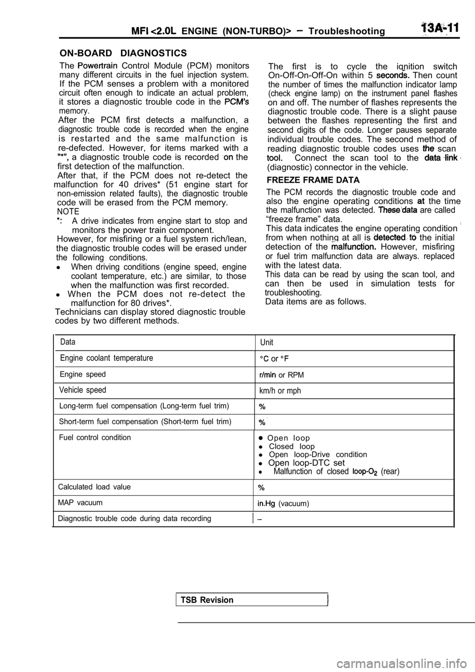
ON-BOARD DIAGNOSTICS
The
Control Module (PCM) monitors
many different circuits in the fuel injection syste m.
If the PCM senses a problem with a monitored
circuit often enough to indicate an actual problem,
it stores a diagnostic trouble code in the
memory.
After the PCM first detects a malfunction, a
diagnostic trouble code is recorded when the engine
i s r e s t a r t e d a n d t h e s a m e m a l f u n c t i o n i s
re-defected. However, for items marked with a
a diagnostic trouble code is recorded the
first detection of the malfunction.
After that, if the PCM does not re-detect the
malfunction for 40 drives* (51 engine start for
non-emission related faults), the diagnostic troubl e
code will be erased from the PCM memory.
NOTE
A drive indicates from engine start to stop and
monitors the power train component.
However, for misfiring or a fuel system rich/lean,
the diagnostic trouble codes will be erased under
the following conditions.
lWhen driving conditions (engine speed, engine
coolant temperature, etc.) are similar, to those
when the malfunction was first recorded.
l When the PCM does not re-detect the
malfunction for 80 drives*.
Technicians can display stored diagnostic trouble
codes by two different methods.
ENGINE (NON-TURBO)> Troubleshooting
The first is to cycle the ignition switch
On-Off-On-Off-On within 5
Then count
the number of times the malfunction indicator lamp
(check engine lamp) on the instrument panel flashes
on and off. The number of flashes represents the
diagnostic trouble code. There is a slight pause
between the flashes representing the first and
second digits of the code. Longer pauses separate
individual trouble codes. The second method of
reading diagnostic trouble codes uses
scan
Connect the scan tool to the
(diagnostic) connector in the vehicle.
FREEZE FRAME DATA
The PCM records the diagnostic trouble code and
also the engine operating conditions the time
the malfunction was detected. are called
“freeze frame” data.
This data indicates the engine operating condition
from when nothing at all is the initial
detection of the
However, misfiring
or fuel trim malfunction data are always. replaced
with the latest data.
This data can be read by using the scan tool, and
can then be used in simulation tests for
troubleshooting.
Data items are as follows.
DataUnit
Engine coolant temperature
Engine speed
Vehicle speed
or
or RPM
km/h or mph
Long-term fuel compensation (Long-term fuel trim)
Short-term fuel compensation (Short-term fuel trim)
Fuel control condition O p e n l o o p
l Closed loop
l Open loop-Drive condition
l Open loop-DTC set
lMalfunction of closed (rear)
Calculated load value
MAP vacuum
(vacuum)
Diagnostic trouble code during data recording
TSB Revision
Page 396 of 2103

ENGINE (NON-TURBO)> Troubleshooting
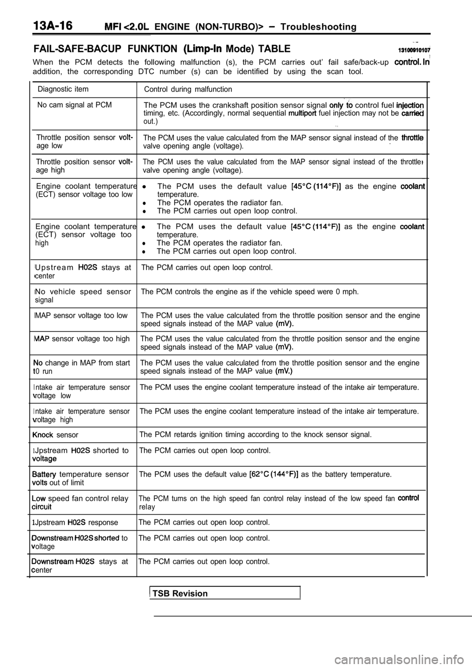
FAIL-SAFE-BACUP FUNKTION Mode) TABLE
When the PCM detects the following malfunction (s), the PCM carries out’ fail safe/back-up
addition, the corresponding DTC number (s) can be i dentified by using the scan tool.
I
I
I
I
I
1
1
Diagnostic item
Control during malfunction
No cam signal at PCM
The PCM uses the crankshaft position sensor signal control fuel timing, etc. (Accordingly, normal sequential fuel injection may not be
out.)
Throttle position sensor The PCM uses the value calculated from the MAP sens or signal instead of the age low
valve opening angle (voltage).
Throttle position sensor The PCM uses the value calculated from the MAP sens or signal instead of the throttle
age high
valve opening angle (voltage).
Engine coolant temperature l
The PCM uses the default value as the engine
(ECT) sensor voltage too low temperature.
lThe PCM operates the radiator fan.
lThe PCM carries out open loop control.
Engine coolant temperature lThe PCM uses the default value
as the engine
(ECT) sensor voltage tootemperature.
highlThe PCM operates the radiator fan.
lThe PCM carries out open loop control.
U p s t r e a m
stays atThe PCM carries out open loop control.
center
No vehicle speed sensorThe PCM controls the engine as if the vehicle speed were 0 mph.
signal
MAP sensor voltage too low The PCM uses the value ca lculated from the throttle position sensor and the engine
speed signals instead of the MAP value
sensor voltage too high The PCM uses the value calc ulated from the throttle position sensor and the engine
speed signals instead of the MAP value
change in MAP from start The PCM uses the value cal culated from the throttle position sensor and the engine
0 runspeed signals instead of the MAP value
ntake air temperature sensorThe PCM uses the engine coolant temperature instead of the intake air temperature.
roltage low
ntake air temperature sensor
The PCM uses the engine coolant temperature instead of the intake air temperature.
roltage high
sensorThe PCM retards ignition timing according to the kn
ock sensor signal.
Jpstream shorted toThe PCM carries out open loop control.
temperature sensorThe PCM uses the default value as the battery temperature.
out of limit
speed fan control relayThe PCM turns on the high speed fan control relay i nstead of the low speed fan
relay
Jpstream responseThe PCM carries out open loop control.
to The PCM carries out open loop control.
oltage
stays atThe PCM carries out open loop control.
enter
TSB Revision
Page 399 of 2103

ENGINE (NON-TURBO)>
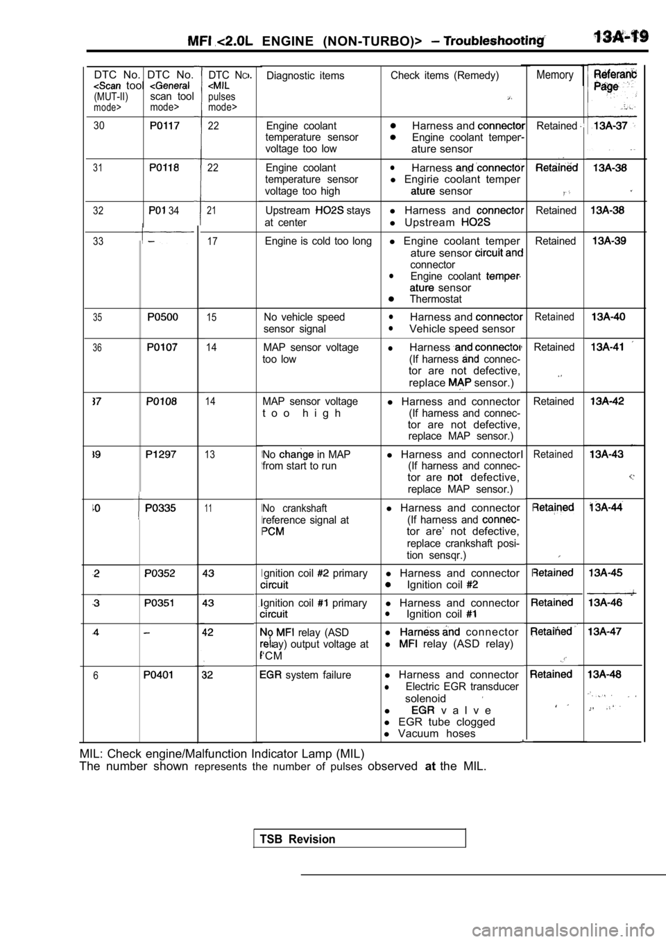
1MemoryDiagnostic itemsCheck items (Remedy)
Engine coolantHarness and
temperature sensorEngine coolant temper
voltage too low
ature sensor
Engine coolantlHarness
temperature sensorl Engirie coolant temper
voltage too high sensor
Upstream staysl Harness and
at centerl Upstream
Engine is cold too longl Engine coolant temper
ature sensor
connectorlEngine coolant
sensor
Thermostat
No vehicle speed
lHarness and
sensor signallVehicle speed sensor
MAP sensor voltagelHarness
too low (If harness connec-
tor are not defective, replace
sensor.)
MAP sensor voltagel Harness and connector
t o o h i g h
(If harness and connec-
tor are not defective,
replace MAP sensor.)
No
in MAPl Harness and connector
from start to run (If harness and connec-
tor are defective,
replace MAP sensor.)
No crankshaftl Harness and connector
reference signal at (If harness and
tor are’ not defective,
replace crankshaft posi-
tion sensqr.)
gnition coil
primaryl Harness and connector
Ignition coil
gnition coil primaryl Harness and connectorlIgnition coil
relay (ASDl connector
ay) output voltage atl relay (ASD relay)
‘CM
system failurel Harness and connector
lElectric EGR transducer
solenoid
l v a l v e
l EGR tube clogged
l Vacuum hoses
DTC NC
pulses
mode>
DTC No. DTC No. tool (MUT-II)scan toolmode>mode>
30
31
32 34
1
I
I
I
I
Retained22
22
,
I
I
I
Retained
Retained
21
17
15
14
14
33
35Retained
36Retained
Retained
13Retained
11
6
MIL: Check engine/Malfunction Indicator Lamp (MIL)
The number shown represents the number of pulses observedatthe MIL.
TSB Revision
Page 402 of 2103

ENGINE (NON-TURBO)> Troubleshooting
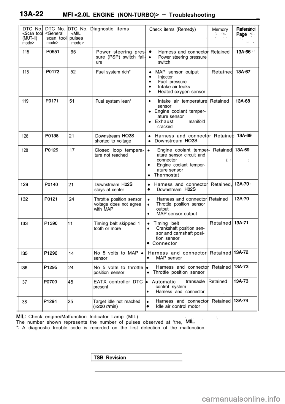
DTC No. DTC No. DTC No. Diagnostic i t e m s
Check items (Remedy) Memory tool
115 65 Power steering pres- Harness and connector Retained
sure (PSP) switch fail-
lPower steering pressure
ureswitch
118 52Fuel system rich*l MAP sensor output R e t a i n e dlInjectorlFuel pressurelIntake air leakslHeated oxygen sensor
119 51Fuel system lean*lIntake air temperature Retained
sensor
l Engine coolant temper-
ature sensor
l E x h a u s t
manifold
cracked
126 21
128 17
Downstreaml H a r n e s s a n d c o n n e c t o r R e t a i n e d
shorted to voltagel Downstream
Closed loop tempera- lEngine coolant temper- Retained
ture not reached ature sensor circuit and
connector
lEngine coolant temper-
ature sensor
l Thermostat
21
24
11
Downstreaml Harness and connector Retained,
stays at centerDownstream
Throttle position sensorlHarness and connector Retained
voltage does not agreelThrottle position sensor
with MAP output
lMAP sensor output
Timing belt skipped 1 l
Timing belt R e t a i n e d
tooth or morelCrankshaft position sen-
sor and camshaft posi-
tion sensor
C o n n e c t o r
37
14
24
45 No 5 volts to MAP
l H a r n e s s a n d c o n n e c t o r R e t a i n e d
sensorlMAP sensor
No 5 volts to throttle lHarness and connector Retained
position sensorl
Throttle position sensor
EATX controller DTC l A u t o m a t i c transaxle Retained
present
control systemlHarness and connector
38 25Target idle not reachedlHarness and connector Retained
Idle air control motor
Check engine/Malfunction Indicator Lamp (MIL)
The number shown represents the number of pulses ob served at ‘the,
A diagnostic trouble code is recorded on the first detection of the malfunction.
TSB Revision
Page 417 of 2103
![MITSUBISHI SPYDER 1990 Service Repair Manual ENGINE (NON-TURBO)>
Scan tool 27
Code scan tool Throttle Position Sensor Voltage
No. High
24
[Comment] Sensor circuit openBackgroundl position sensor failed
lThe sensor consis MITSUBISHI SPYDER 1990 Service Repair Manual ENGINE (NON-TURBO)>
Scan tool 27
Code scan tool Throttle Position Sensor Voltage
No. High
24
[Comment] Sensor circuit openBackgroundl position sensor failed
lThe sensor consis](/manual-img/19/57345/w960_57345-416.png)
ENGINE (NON-TURBO)>
Scan tool 27
Code scan tool Throttle Position Sensor Voltage
No. High
24
[Comment] Sensor circuit openBackgroundl position sensor failed
lThe sensor consists of a resistor that provides a to the PCM based S e n s o r g r o u n d c i r c u i t on the position of the throttle blade.l The PCM uses throttle body position information to adjust fuel injector width.
Range of Check
l ignition switch: ON
Set Condition
l Throttle position sensor output remains more than for 1 second.
NGCheck the throttle position sensor. (TPS) (Refer to Replace
OK
Measure at the TPS connector lDisconnect the connector, and measure at the harnes s side.
l Continuity between 1 and ground
OK: Continuity
OK
Scan tool 30
Code General scan tool Engine Coolant Temperature
No.Sensor Voltage Too
22
[Comment]l Sensor shorted to Backgroundl Sensor internally shortedlData from the engine temperature sensor is used in most fuel and spark related
l PCM failed
control functions.
Range of Checkl Ignition switch: ON ,
Set ConditionEngine temperature sensor output remains less than 0.51 for 3 seconds.
Check the wire between We PCM and TPS Repair, if necessary.
NG Check the following connectors: Repair ,
Check trouble symptom.
OKNGCheck the harness wire between the PCM and the TPS connector.
NG
Replace
Replace
(Refer to
OK
Repair
OK
Check trouble symptom.
NG N G
the Repair
temperature sensor connector.
OK
Replace the PCM.
TSB Revision
Page 418 of 2103
![MITSUBISHI SPYDER 1990 Service Repair Manual ENGINE
Scan tool 31 .
Code General scan tool Engine Coolant Temperature
No.Sensor Voltage Too High
22
[Comment]
Backgroundl Sensor signal circuit open
Data from the engine coolant MITSUBISHI SPYDER 1990 Service Repair Manual ENGINE
Scan tool 31 .
Code General scan tool Engine Coolant Temperature
No.Sensor Voltage Too High
22
[Comment]
Backgroundl Sensor signal circuit open
Data from the engine coolant](/manual-img/19/57345/w960_57345-417.png)
ENGINE
Scan tool 31 .
Code General scan tool Engine Coolant Temperature
No.Sensor Voltage Too High
22
[Comment]
Backgroundl Sensor signal circuit open
Data from the engine coolant temperature sensor is used in most fuel and spark relatedl
Sensor internally openlcontrol functions.l PCM failedl When DTC is set, the PCM uses a default value as th e engine coolant temperature, andthe vehicle enters the limp-in mode.Range of Checkl Ignition switch: ON ,
Set Condition,lEngine coolant temperature sensor output voltage re mains more than for 3 seconds.
(Refer to
NG Replace
OK
Measure at the engine coolant temperature sensor lDisconnect the connector, and measure at the harnes s side.
l Continuity between 1 and ground
OK: Continuity
OK
OK
NG
NG
Check the harness wire between the PCM and the engi ne coolanttemperature sensor connector. Repair, if
Repair..
.
Check the harness wire between the coolanttemperature sensor connector.
[Comment] OK
Replace the PCM.
NG
Repair
Upstream Stays
Backgroundl
Sensor output voltage is checked.lIf voltage stays at center instead of switching, an open circuit is likely.
Range of Check
l 2 minutes after starting engine
l Engine coolant temperature: More than
Set ConditionNeither rich nor lean condition is detected from th e upstream heated oxygen sensor input.(Voltage is 0.5 volts for 1.5 minutes)
Check the heated oxygen sensor (front). [Refer to
l Heated oxygen sensor (front) Sensor signal circuit l PCM failed
OK. .
NGCheck the following connectors: Repair
Check trouble symptom.
Check the harness wire between Repair
sensor (front) connector.
OK
Replace the PCM.
TSB Revision
Page 419 of 2103
![MITSUBISHI SPYDER 1990 Service Repair Manual ENGINE (NON-TURBO)>
Scan tool 33
General scan tool is Too LongP r o b a b l e
[Comment]
Backgroundl Thermostat fully
l When the engine is started, the engine coolant temp eratur MITSUBISHI SPYDER 1990 Service Repair Manual ENGINE (NON-TURBO)>
Scan tool 33
General scan tool is Too LongP r o b a b l e
[Comment]
Backgroundl Thermostat fully
l When the engine is started, the engine coolant temp eratur](/manual-img/19/57345/w960_57345-418.png)
ENGINE (NON-TURBO)>
Scan tool 33
General scan tool is Too LongP r o b a b l e
[Comment]
Backgroundl Thermostat fully
l When the engine is started, the engine coolant temp erature The PCM checksl
Engine temperature sensor failedlthat the engine coolant rises the specified value within a sufficient period aft er theEngine coolant temperature
engine is started. improperly connected
l PCM failed
Range of Check
l Vehicle speed: More than 28 mph
l
minutes after starting engine
Set Condition
lEngine coolant temperature does not rise to 71 ,
Replace
(Refer to Replace
Repair
.
NG Repairtemperature sensor connector.
OK
Replace the PCM.
TSB Revision
Page 420 of 2103
![MITSUBISHI SPYDER 1990 Service Repair Manual ENGINE
I Scan tool 35
Code General scan tool
No.No Vehicle Speed Sensor Signal
15
[Comment]
Background
lThe speed sensor serves as a PCM input switching voltage between 0 an MITSUBISHI SPYDER 1990 Service Repair Manual ENGINE
I Scan tool 35
Code General scan tool
No.No Vehicle Speed Sensor Signal
15
[Comment]
Background
lThe speed sensor serves as a PCM input switching voltage between 0 an](/manual-img/19/57345/w960_57345-419.png)
ENGINE
I Scan tool 35
Code General scan tool
No.No Vehicle Speed Sensor Signal
15
[Comment]
Background
lThe speed sensor serves as a PCM input switching voltage between 0 and 5volts.lOnce the vehicle is in motion and the throttle is open, information from the sensor is
sampled every 11 milliseconds and compared to a min imum threshold equal to 1 mph.
lIf the sensors output voltage indicates a speed higher than this threshold, the sensor
is considered to be operating normally.
lFailure of the sensor would be quite noticeable bec ause the speedometer would fail tooperate.Diagnostic features that depend on the speed sensor may never execute if this component
fails.
of Check Engine coolant temperature: or more Transaxle: Other than or range only). 31 seconds after starting engine Brakes not applied Throffle valve: Open Engine: 1600 or more Difference between the atmospheric pressure and in take manifold pressure:
34 (10 or more Condition Vehicle speed: Less than lmph for 11 seconds
Measure at the speed sensor connector
l Disconnect the connector, and measure at the harnes s side.
l Voltage between 1 and ground
(Ignition switch: ON)
O K :
l Continuity between 2 and ground
OK: Continuity
OK
OK
Check trouble
Open or shorted. circuitS p e e d o m e t e r d a m a g e d Open supply circuit
Open sensor ground circuit
Vehicle speed sensor failed PCM failed
Repair
Check the harness wire between the PCM and the spee d sensor
connector. Repair, if necessary.
N G Check the following connectors: I Repair
SCAN TOOL SENSOR READ TESTS (Data list)
Replace the vehicle speed sensor.
connector.
N G NG
Repair
TSB Revision