1990 MITSUBISHI SPYDER coolant temperature
[x] Cancel search: coolant temperaturePage 518 of 2103
ENGINE
AND ENGINE> G e n e r a l
ENGINE (TURBO) AND ENGINE>13199910319
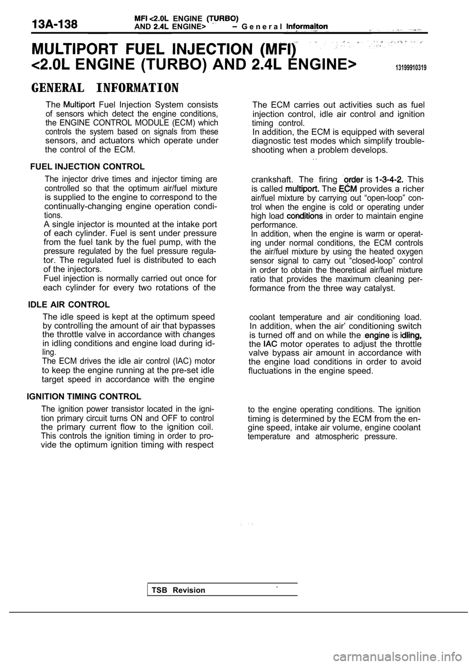
GENERAL INFORMATIONThe
Fuel Injection System consists
of sensors which detect the engine conditions,
the ENGINE CONTROL MODULE (ECM) which
controls the system based on signals from these
sensors, and actuators which operate under
the control of the ECM.
FUEL INJECTION CONTROL
The injector drive times and injector timing are
controlled so that the optimum air/fuel mixture
is supplied to the engine to correspond to the
continually-changing engine operation condi-
tions.
A single injector is mounted at the intake port
of each cylinder. Fuel is sent under pressure
from the fuel tank by the fuel pump, with the
pressure regulated by the fuel pressure regula-
tor. The regulated fuel is distributed to each
of the injectors.
Fuel injection is normally carried out once for
each cylinder for every two rotations of the
IDLE AIR CONTROL The idle speed is kept at the optimum speed
by controlling the amount of air that bypasses
the throttle valve in accordance with changes
in idling conditions and engine load during id-
ling.
The ECM drives the idle air control (IAC) motor
to keep the engine running at the pre-set idle
target speed in accordance with the engine
IGNITION TIMING CONTROL
The ignition power transistor located in the igni-
tion primary circuit turns ON and OFF to control
the primary current flow to the ignition coil.
This controls the ignition timing in order to pro-
vide the optimum ignition timing with respect The ECM carries out activities such as fuel
injection control, idle air control and ignition
timing control.
In addition, the ECM is equipped with several
diagnostic test modes which simplify trouble-
shooting when a problem develops.
. .
crankshaft. The firing is This
is called
The provides a richer
air/fuel mixture by carrying out “open-loop” con-
trol when the engine is cold or operating under high load
in order to maintain engine
performance. In addition, when the engine is warm or operat-
ing under normal conditions, the ECM controls
the air/fuel mixture by using the heated oxygen
sensor signal to carry out “closed-loop” control
in order to obtain the theoretical air/fuel mixture
ratio that provides the maximum cleaning per-
formance from the three way catalyst.
coolant temperature and air conditioning load.
In addition, when the air’ conditioning switch
is turned off and on while the
is
the motor operates to adjust the throttle
valve bypass air amount in accordance with
the engine load conditions in order to avoid
fluctuations in the engine speed.
to the engine operating conditions. The ignition
timing is determined by the ECM from the en-
gine speed, intake air volume, engine coolant
temperature and atmospheric pressure.
TSB Revision
Page 519 of 2103
ENGINE (TURBO)
ENGINE>
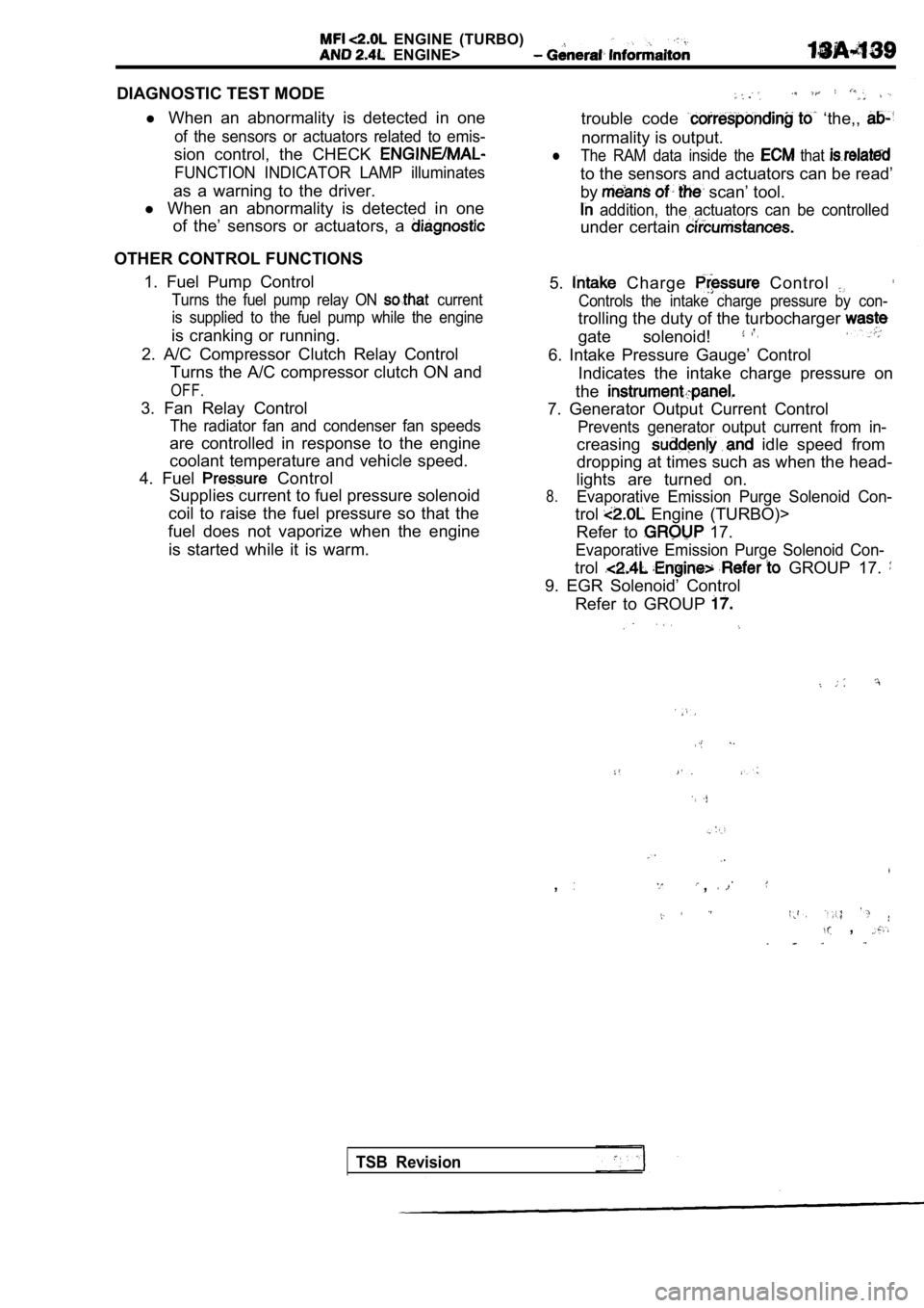
DIAGNOSTIC TEST MODEl When an abnormality is detected in one
of the sensors or actuators related to emis-
sion control, the CHECK
FUNCTION INDICATOR LAMP illuminates
as a warning to the driver.
l When an abnormality is detected in one
of the’ sensors or actuators, a
OTHER CONTROL FUNCTIONS
1. Fuel Pump Control
Turns the fuel pump relay ON current
is supplied to the fuel pump while the engine
is cranking or running.
2. A/C Compressor Clutch Relay Control Turns the A/C compressor clutch ON and
OFF.
3. Fan Relay Control
The radiator fan and condenser fan speeds
are controlled in response to the engine
coolant temperature and vehicle speed.
4. Fuel
Control
Supplies current to fuel pressure solenoid
coil to raise the fuel pressure so that the
fuel does not vaporize when the engine
is started while it is warm.
trouble code ‘the,,
normality is output.
lThe RAM data inside the that
to the sensors and actuators can be read’
by
scan’ tool.
addition, the actuators can be controlled
under certain
5. Charge Control
Controls the intake charge pressure by con-
trolling the duty of the turbocharger
gate solenoid!
6. Intake Pressure Gauge’ Control Indicates the intake charge pressure on
the
7. Generator Output Current Control
Prevents generator output current from in-
creasing idle speed from
dropping at times such as when the head-
lights are turned on.
8.Evaporative Emission Purge Solenoid Con-
trol Engine (TURBO)>
Refer to
17.
Evaporative Emission Purge Solenoid Con-
trol GROUP 17.
9. EGR Solenoid’ Control
Refer to GROUP
,,
,
TSB Revision
Page 520 of 2103
E N G I N E ( T U R B O )
AND
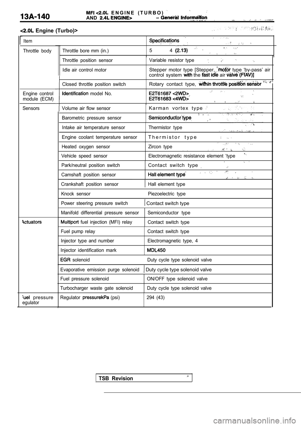
Engine (Turbo)>
Item
Throttle bodyThrottle bore mm (in.)5 4
Engine control
module (ECM)
Sensors
pressure
egulator
Volume air flow sensor
Barometric pressure sensorK a r m a n v o r t e x t y p e , ,
Intake air temperature sensor Thermistor type
Engine coolant temperature sensor
T h e r m i s t o r t y p e
Heated oxygen sensor Zircon type
Vehicle speed sensor Electromagnetic resistance elem ent ‘type
Park/neutral position switchContact switch type .
Camshaft position sensor
Crankshaft position sensorHall element type
Throttle position sensor
Idle air control motor Variable resistor type
Stepper motor type [Stepper. type ‘by-pass’ air
control system
the air
Closed throttle position switch
model No.
Rotary contact type,
,
Knock sensor Piezoelectric type
Power steering pressure switch
Contact switch type
Manifold differential pressure sensor Semiconductor type
fuel injection (MFI) relay
Contact switch type
Fuel pump relay
Injector type and number
Injector identification mark Contact switch type
Electromagnetic type, 4
solenoid Duty cycle type solenoid valve
Evaporative emission purge solenoid
Duty cycle type solenoid valve
Fuel pressure solenoid
Turbocharger waste gate solenoid ON/OFF type solenoid valve
Duty cycle type solenoid valve
Regulator
(psi) 294 (43)
TSB Revision
Page 521 of 2103
ENGINE (TURBO)
AND
ENGINE> General
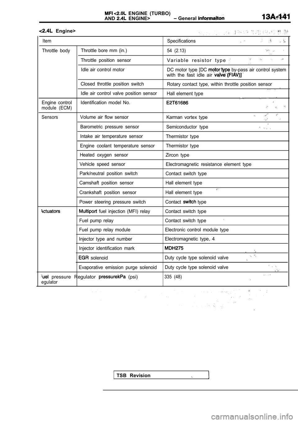
Engine>
ItemSpecifications
Throttle body Throttle bore mm (in.)54 (2.13)
Throttle position sensorV a r i a b l e r e s i s t o r t y p e
Idle air control motor
DC motor type [DC by-pass air control system
with the fast idle air
Closed throttle position switch
Rotary contact type, within throttle position senso r
Idle air control valve position sensor
Hall element type
Engine control Identification model No.
module (ECM)
SensorsVolume air flow sensor Karman vortex type
Barometric pressure sensorSemiconductor type.
Intake air temperature sensorThermistor type
Engine coolant temperature sensor Thermistor type
Heated oxygen sensor Zircon type
Vehicle speed sensor Electromagnetic resistance element type
Park/neutral position switch Contact switch type
Camshaft position sensor Hall element type
Crankshaft position sensor Hall element type
Power steering pressure switch Contact type
fuel injection (MFI) relay Contact switch type
Fuel pump relay Contact switch type
Fuel pump relay module Electronic control module typ e
Injector type and number Electromagnetic type, 4
Injector identification mark
,
solenoid Duty cycle type solenoid valve
Evaporative emission purge solenoid
Duty cycle type solenoid valve
pressure Regulator (psi)335 (48)
egulator
TSB Revision
Page 522 of 2103
E N G I N E ( T U R B O )
AND
ENGINE> General . .
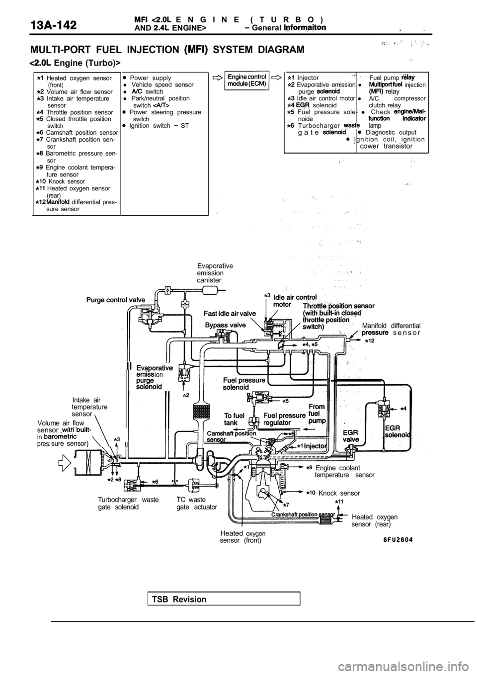
MULTI-PORT FUEL INJECTION SYSTEM DIAGRAM
Engine (Turbo)>
Heated oxygen sensor(front) Volume air flow sensor Intake air temperaturesensor Throttle position sensor Closed throttle positionswitch Camshaft position sensor Crankshaft position sen-sor Barometric pressure sen-sor Engine coolant tempera- ture sensor
Knock sensor Heated oxygen sensor(rear) differential pres-
sure sensor
Power supply
l Vehicle speed sensor
l
switch
l Park/neutral position
switch
Power steering pressureswitch Ignition switch ST
Enginecontrol Injector . Fuel pump
Evaporative emission l injectionpurge relay Idle air control motor lA/Ccompressor solenoid clutch relay Fuel pressure sole-
l C h e c knoide T u r b o c h a r g e r lampg a t e Diagnostic output I g n i t i o n c o i l , i g n i t i o n cower transistor
,
Evaporative
emission
canister
TSB Revision
Manifold differential s e n s o r
IIion. .
Intake air
temperature
sensor
Volume air flow
sensor . insure sensor) IIpres:
Engine coolant temperature sensor
Turbocharger waste gate solenoid TC waste
gate actuator
Knock sensor
Heated oxygen
sensor (rear)
Heated oxygensensor (front)
Page 523 of 2103

ENGINE (TURBO)
AND ENGINE> General lnformaiton
Engine>
Heated oxygen sensor Power supply(front)l Vehicle speed sensor Volume air flow sensor l switch Intake air temperature Park/neutral positionsensorswitch Throttle position sensor Power steering pressure Closed throttle positionswitch
switchl Ignition switch ST Camshaft position sensor Crankshaft position sen-sor Barometric pressure sen-sor Engine coolant tempera-
ture sensor
valve position sensor Heated oxygen sensor(rear) Manifold differential pres-sure sensor tank differential pres-
sure sensor
,
Engine control Injector l
Fuel pump relay Evaporative emission lFuel pump relay purge solenoid air control motor injection EGR solenoid relay Evaporative emission l ventilation solenoid clutch relay
l C h e c k
o u t p u t coil, ignition
T h r o t t l e s e n s o r ,
control
Intake air
t e m p e r a t u r e
. . . sensor pressure
a
temperature sensor EGR
solenoidHeated oxygen
Fuel tank pressure
sensor (rear) Heated oxygen
Evaporativeemission canisterFuel tank
Crankshaft position sensor
Camshaft positionsensor
TSB Revision
Page 524 of 2103
ENGINE (TURBO)
AND
ENGINE> S e r v i c e
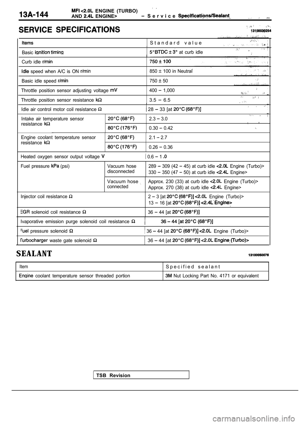
S t a n d a r d v a l u e
Basic at curb idle ,
Curb idle
speed when A/C is ON 850 100 in Neutral
Basic idle speed
750 50
Throttle position sensor adjusting voltage
Throttle position sensor resistance
400 1,000
3.5 6.5
Idle air control motor coil resistance 28 33 [at
Intake air temperature sensor
resistance2.3 3.0,
0.30 0.42
Engine coolant temperature sensor
resistance2.1 2.7
0.26 0.36
Heated oxygen sensor output voltage
0.6 1
Fuel pressure (psi) Vacuum hose disconnected289 309 (42 45) at curb idle Engine (Turbo)>
330
350 (47 50) at curb idle Engine>
Injector coil resistance
solenoid coil resistance
Vacuum hose Approx. 230 (33) at curb idle Engine (Turbo)>
connected Approx. 270 (38) at curb idle
Engine>
2
3 [at Engine (Turbo)>
13
16 [at
36 44 [at
TSB Revision
Ivaporative emission purge solenoid coil resistance
pressure solenoid 36 44 [at Engine (Turbo)>
waste gate solenoid 36 44 [at
SEALANT
Item
coolant temperature sensor threaded portion
S p e c i f i e d s e a l a n t
Nut Locking Part No. 4171 or equivalent
Page 527 of 2103
E N G I N E ( T U R B O )
AND
ENGINE>
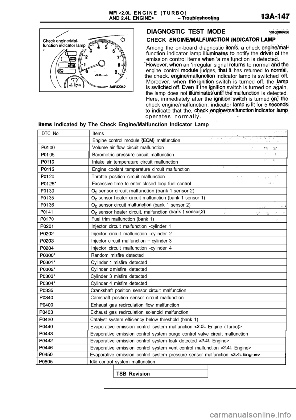
DIAGNOSTIC TEST MODE
CHECK
Among the on-board diagnostic a check
function indicator lamp notify the the
emission control items
‘a malfunction is detected.
an ‘irregular signal to normal
engine control judges, has returned to
the check. indicator lamp is switched
Moreover, when switch is turned off, the
is off. if the switch is turned on again,
the lamp does not is detected.
Here, immediately after the is turned
check engine/malfunction, indicator is for 5
to indicate that the,
o p e r a t e s n o r m a l l y .
Indicated by The Check Engine/Malfunction Indicato r Lamp
00
05
20
30
35
36
41
70
Items
Engine control module
malfunction
Volume air flow circuit malfunction
Barometric
circuit malfunction
Intake air temperature circuit malfunction
Engine coolant temperature circuit malfunction
Throttle position circuit malfunction
Excessive time to enter closed loop fuel control
sensor circuit malfunction (bank 1 sensor 2)
sensor heater circuit malfunction (bank 1 sensor 1 )
sensor circuit (bank 1 sensor 2).
sensor heater circuit, malfunction 1
Fuel trim malfunction (bank 1)
Injector circuit malfunction -cylinder 1
Injector circuit malfunction -cylinder 2
Injector circuit malfunction
cylinder 3
Injector circuit malfunction -cylinder 4
Random misfire detected
Cylinder
misfire detected
Cylinder
2misfire detected
Cylinder 3 misfire detected Cylinder 4 misfire detected
Crankshaft position sensor circuit malfunction
Camshaft position sensor circuit malfunction
Exhaust gas recirculation flow malfunction
Exhaust gas recirculation solenoid malfunction
Catalyst system efficiency below threshold (bank 1) Evaporative emission control system malfunction
Engine (Turbo)>
Evaporative emission control system purge control v alve circuit malfunction
Evaporative emission control system leak detected
Engine>
Evaporative emission control system vent control ma lfunction
Engine>
Evaporative emission control system pressure sensor malfunction
control system malfunction
DTC No.
TSB Revision